Downloaded 25 times


![References
[1]. http://www.radio-electronics.com/info/electronics-design/pcb/pcb-design-
layoutprocess.php
[2].www.viasion.com/PCB/circuit-pcb.pdf
[3].http://www.pyroelectro.com/projects/ir_radar/
[4].http://www.siliconindia.com/aiepic/project/short_range_personal_radarpid=8134.html
[5].http://www.engineersgarage.com/sites/default/files/7805.pdf
[6].http://www.futurlec.com/Datasheet/74ls/74LS04.pdf
[7].http://labdasar.ee.itb.ac.id/lab/EL2195/pendukung%20praktikum/74LS08_2INANDGATE.pdf
[8].http://electroschematics.com/wp-content/uploads/2008/11/lm358.pdf
[9].http://www.omron-ap.co.in/technical_guide/proximity_sensor/index.asp
BOOKS
[1]. Mehta V.K., “ Principles of Electronics “S.Chand & Co. Ltd., New Delhi
[2] Boylstead Robert & Nasceslsky Louis “ Electronic Devices & Circuit Theory”
Prentice Hall of India Private Ltd., New Delhi
[3] Millman Jacob & Halkias C. Christos “Integrated Electronics “
Tata Mc Graw Hill Publishing Ltd., New Delhi.](https://image.slidesharecdn.com/sarvesh-minorprojectreport-170419130339/85/Minor-Project-Report-on-short-range-personal-RADAR-26-320.jpg)

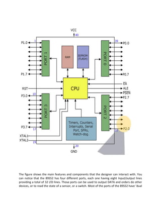
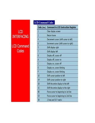
The document is a project report on a 'short range personal radar' developed by students for their engineering degree in electronics and communication. It outlines the design and functionality of a radar system using an 8051 microcontroller, which detects obstacles using RF signals and displays results on an LED panel. The report includes detailed sections on the project's abstract, introduction, working principles, proposed problem statement, work done, and software programming.