This document discusses a new type of gated continuous wave (CW) radar that offers improvements over traditional gated CW radars. It operates using a pulsed transmit signal and gated receive path, along with a receiver bandwidth restricted to only the central frequency components of the received pulse spectrum. This new gated CW radar uses a Performance Network Analyzer in place of a vector network analyzer for higher data acquisition speeds and other enhancements. It provides better accuracy, circularity and lower cost than an equivalent pulsed intermediate frequency radar while maintaining the efficiency advantages of gated CW radars for indoor use.
1. Page 1
CHAPTER 1
INTRODUCTION
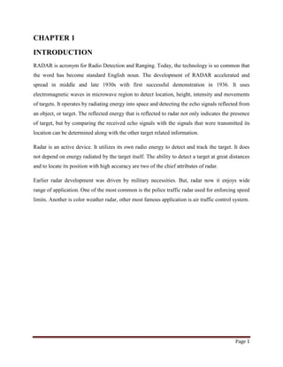
RADAR is acronym for Radio Detection and Ranging. Today, the technology is so common that
the word has become standard English noun. The development of RADAR accelerated and
spread in middle and late 1930s with first successful demonstration in 1936. It uses
electromagnetic waves in microwave region to detect location, height, intensity and movements
of targets. It operates by radiating energy into space and detecting the echo signals reflected from
an object, or target. The reflected energy that is reflected to radar not only indicates the presence
of target, but by comparing the received echo signals with the signals that were transmitted its
location can be determined along with the other target related information.
Radar is an active device. It utilizes its own radio energy to detect and track the target. It does
not depend on energy radiated by the target itself. The ability to detect a target at great distances
and to locate its position with high accuracy are two of the chief attributes of radar.
Earlier radar development was driven by military necessities. But, radar now it enjoys wide
range of application. One of the most common is the police traffic radar used for enforcing speed
limits. Another is color weather radar, other most famous application is air traffic control system.
2. Page 2
CHAPTER 2
LITERATURE SURVEY:
The history of radar starts with experiments by Heinrich Hertz in the late 19th century that
showed that radio waves were reflected by metallic objects. This possibility was suggested
in James Clerk Maxwell's seminal work on electromagnetism. However, it was not until the early
20th century that systems able to use these principles were becoming widely available, and it was
German inventor Christian Hulsmeyer who first used them to build a simple ship detection
device intended to help avoid collisions in fog. Numerous similar systems were developed over
the next two decades.
The term RADAR was coined in 1940 by the United States Navy as
an acronym for radio detection and ranging, this was a cover for the highly secret
technology. Thus, a true radar system must both detect and provide range (distance) information
for a target. Before 1934, no single system gave this performance; some systems were omni-
directional and provided ranging information, while others provided rough directional
information but not range. A key development was the use of pulses that were timed to provide
ranging, which were sent from large antennas that provided accurate directional information.
Combining the two allowed for accurate plotting of targets.
Applications of radar are very vast. Today, through its many and diverse applications, radar is a
key tool for remotely sensing and monitoring the environment and for the tracking and
surveillance of both civil and military objects.
2.1 FUTURE RESEARCH:
The focus is in the use of radar for surveillance and environmental monitoring. It brings together
research groups from the School of Electrical and Electronic Engineering and the Discipline of
Physics in the School of Science together with various external organizations such as the
Australian Defense Science and Technology Organisation, the Bureau of Meteorology, the
Australian Antarctic Division and commercial companies such as Raytheon Australia.
Key research themes in the Centre are in the area of radar systems and technology, RF
propagation and radar signal processing. The applications focus for the Centre's research will be
3. Page 3
the areas of environmental and atmospheric monitoring through radar sensing, surveillance and
radar systems design.
Radar technology currently used to support tactical operations aboard Navy ships will soon be
adapted for a new purpose – weather detection. This state-of-the-art phased array radar
technology may help forecasters of the future provide earlier warnings for tornadoes and other
types of severe and hazardous weather.
4. Page 4
CHAPTER 3
PRINCIPLE OF WORKING OF BASIC RADAR
Radar involves the transmission of pulses of electromagnetic waves by means of a directional
antenna. A radar system has a transmitter that emits radio waves called radar signals in
predetermined directions. Some of the pulses are reflected by objects that intercept them. When
these come into contact with an object they are usually reflected or scattered in many directions.
Transmitted signal
Antenna
Echo signal
Range to target
Target detection and ranging
Fig 3.1 Basic radar working
The working of basic radar is shown in fig 3.1. Radar signals are reflected especially well by
materials of considerable electrical conductivity. The reflections are picked up by a receiver,
processed electronically, and converted into visible form by means of a cathode-ray tube. The
range of the object is determined by measuring the time it takes for the radar signal to reach the
object and return. The object's location with respect to the radar unit is determined from the
direction in which the pulse was received. In most radar units the beam of pulses is continuously
rotated at a constant speed, or it is scanned (swung back and forth) over a sector, also at a
Transmitter
Receiver
Target
5. Page 5
constant rate. If the object is moving either toward or away from the transmitter, there is a slight
equivalent change in the frequency of the radio waves, caused by the Doppler effect. The
velocity of the object is measured by applying the Doppler principle, if the object is approaching
the radar unit, the frequency of the returned signal is greater than the frequency of the
transmitted signal, if the object is receding from the radar unit, the returned frequency is less
and if the object is not moving relative to the radar unit, the return signal will have the same
frequency as the transmitted signal
Radar receivers are usually, but not always, in the same location as the transmitter. Although the
reflected radar signals captured by the receiving antenna are usually very weak, they can be
strengthened by electronic amplifiers. More sophisticated methods of signal processing are also
used in order to recover useful radar signals.
The general requirement for any radar system is summarized as below:
1. The radar transmitter should remain silent during the echo period.
2. The transmitted pulse should be quite powerful to counter the attenuation during forward
and return journeys.
3. The received echo pulse being weak, the receiver should be extremely sensitive and at the
same time immune to noise signals. It should have necessary amplification, signal
processing circuitry.
4. The radar antenna should be highly directive and have a large gain so it can radiate a
strong signal and receive a weak pulse.
5. Pulse repetition frequency (prf) of radar should be high.
6. Page 6
3.1 Radar transmitter
The radar transmitter produces the short duration high-power RF pulses of energy that are
radiated into space by the antenna. The radar transmitter is required to have the following
technical and operating characteristics:
1) The transmitter must have the ability to generate the required mean RF power and the
required peak power.
2) The transmitter must have a suitable RF bandwidth.
3) The transmitter must have a high RF stability to meet signal processing requirements.
4) The transmitter must be easily modulated to meet waveform design requirements.
5) The transmitter must be efficient, reliable and easy to maintain and the life expectance
and the cost of the output device must be acceptable.
3.2 Radar receiver:
The function of radar receiver is to detect the desired echo signals in the presence of noise,
interference and clutter, clutter is defined as any unwanted radar echo. These clutter make
difficult the detection of wanted signals. The design of radar receiver will depend not only on the
type of waveform to be detected but also on the nature of noise interference and clutter echoes.
The radar receiver is required to:
1) Amplify the received signals without adding noise or introducing any form of distortions.
2) Reject interfering signals so that the required can be optimally detected.
3) Receiver should be designed to have sufficient gain, amplification, stability.
4) Receiver should provide large dynamic range to accommodate large clutter signals.
5) Timing and reference signals are needed to properly extract target information.
7. Page 7
CHAPTER 4
Free space Radar equations:
The radar range equation relates the range of a radar to the characteristics of the transmitter,
receiver, antenna, target and the medium. Free space actually means that there are no obstacles
between radar antenna and the target. Also the free space medium is transparent and
homogenous with respect to the refractive index at radar frequency.
If the power of a radar transmitter is denoted by Pt and if an isotropic antenna (one which
radiates uniformly in all the directions) then the power density at a distance R from the radar is
equal to the transmitted power divided by the surface area of sphere of radius R i.e. power
density at a distance R from the isotropic source,
= Pt / 4ПR2
watts/m2
…(4.1)
Radar usually employ directive antennas to direct the transmitted power Pt into one particular
direction. The gain G of an antenna is a measure of the increased power radiated in the direction
of the target as compared with the power that would have been radiated from an isotropic
antenna.
Power density at a distance R from directive antenna of power gain
= Pt G / 4ПR2
watts/m2
…(4.2)
The target intercepts the portion of transmitted power and radiates it in various directions. A
measure of the incident power intercepted by the target and reradiated back in the direction of
radar is denoted as the radar cross-section of the target (б).
The total power intercepted by a target having an area ‘б’ is,
= (Pt G / 4П R2
).б watts …(4.3)
Where б is also defined as the area of the target as seen by the radar. It has units of area in m2
.
б is a characteristic of a particular target and is a measure of its size and shape. The power
density of echo signal at the radar station is
= (PtGб / 4ПR2
) . (1/4ПR2
) = PtGб/ (4ПR2
)2
watts …(4.4)
The radar antenna captures the portion of of the echo power.if the effective area of the receiving
antenna is denoted byAe, the power Pr received by the radar is given by,
Pr = PtGбAe / (4ПR2
)2
watts …(4.5)
8. Page 8
Maximum radar range is the distance beyond which the target cannot be detected. It occurs when
the received echo signal power Pr, just equals the minimum detectable signal (Smin).
i.e. when Pr = Smin, R = Rmax and when substituted in Eq. 11.5 we get,
Smin = PtGбAe / (4П)2
R4
max
Rmax = [PtGбAe /(4П)2
Smin]1/4
…(4.6)
From the antenna theory, we know that
G = 4ПAe / λ2
Where, λ= wavelength of the radiated energy,
Ae = effective area of receiving antenna,
G = transmitter gain
Since radar generally use the same antenna for both transmitter and receiver, the above
expression for G can be substituted in Rmax relation. Then,
Rmax = [Pt б Ae / (4П)2
Smin]1/4
Rmax = [PtAe
2
б / 4Пλ2
Smin]1/4
…(4.7)
Also, Ae = Gλ2
/ 4П,
Rmax = [Pt(Gλ2
/4П)2
б / 4Пλ2
Smin]1/4
Rmax = [Pt Gλ2
б / (4П)2
Smin]1/4
…(4.8)
Equations (4.7) and (4.8) is the two alternate form of maximum radar range equation.
9. Page 9
CHAPTER 5
TYPES OF RADAR
Depending on the desired information, radar sets must have different qualities and technologies.
One such different qualities and techniques radar sets are classified in fig. 5.1.
Fig. 5.1 types of radar.
5.1 PRIMARY RADAR:
A Primary Radar transmits high-frequency signals toward the targets. The transmitted pulses are
reflected by the target and then received by the same radar. The reflected energy or the echoes
are further processed to extract target information. This means, unlike secondary radar a primary
radar unit receive its own emitted signals as an echo again.
RADAR
PRIMARY SECONDARY
CONTINUOUS
WAVE
PULSE
MODULATED UNMODULATED MTI DOPPLER
10. Page 10
5.1.1 CONTINUOUS WAVE RADAR:
Continuous wave radars continuously transmit a high-frequency signal and the reflected energy
is also received and processed continuously. These radars have to ensure that the transmitted
energy doesn’t leak into the receiver (feedback connection). CW radars measures radial velocity
of the target using Doppler Effect. If there is relative motion between the radar and the target, the
shift in carrier frequency (Doppler shift) of the reflected wave becomes a measure of targets
relative velocity. The block diagram of continuous wave radar is shown in fig. 5.2.
F o f o
F o ± f d
f0 ± f d
f d f d
Fig. 5.2 block diagram of continuous wave radar
The transmitter generates a continuous oscillations of frequency fo which is radiated by radar
antenna. A portion of this radiated energy is intercepted by target and reradiated energy is
collected by the receiver antenna. If the target is moving with the velocity vr relative to the radar,
the received signal will be shifted in frequency from the transmitted frequency fo by the amount
fd. The plus sign for an approaching target and minus sign for a receding target. The
receivedecho signal (fo±fd) enters the radar via the antenna and is mixed in a detector mixer with
a portion of a transmitter signal fo to produce the Doppler frequency fd. The purpose of using a
beat frequency amplifier is to eliminate echo from stationary targets and to amplify the Doppler
echo signal to a level where it can operate an indicating device such as frequency meter.
CW Transmitter
Detector
(mixer)
Beat frequency
amplifier
Indicator
Target
11. Page 11
ADVANTAGES:
1) It uses low transmitting power, low power consumption.
2) It has simple circuitry and it is small in size.
3) Unlike pulse radar CW radar is able to detect an aircraft inspite of fixed objects.
DISADVANTAGES:
1) Practical application of CW radar is limited by the fact that several targets at a given
bearing tend to cause confusion.
2) Range discrimination can be achieved only by introducing very costly complex circuitry.
3) It is not capable of indicating the range of target an can show only its velocity.
CW RADARS TYPES
Unmodulated
An example of unmodulated CW radar is speed gauges used by the police. The transmitted signal
of these equipments is constant in amplitude and frequency. CW radar transmitting unmodulated
power can measure the speed only by using the Doppler-effect. It cannot measure a range and it
cannot differ between two reflecting objects.
Modulated
Unmodulated CW radars have the disadvantage that they cannot measure range, because run
time measurements is not possible (and necessary) in unmodulated CW-radars. This is achieved
in modulated CW radars using the frequency shifting method. In this method, a signal that
constantly changes in frequency around a fixed reference is used to detect stationary objects.
Frequency is swept repeatedly between f1 and f2. On examining the received reflected
frequencies (and with the knowledge of the transmitted frequency), range calculation can be
done.
12. Page 12
5.2 SECONDARY RADAR:
Secondary radar units work with active answer signals. In addition to primary radar, this type of
radar uses a transponder on the airborne target The ground unit, called interrogator, transmits
coded pulses (after modulation) towards the target. The transponder on the airborne object
receives the pulse, decodes it, induces the coder to prepare the suitable answer, and then
transmits the interrogated information back to the ground unit. The interrogator/ground unit
demodulates the answer. The information is displayed on the display of the primary radar. The
secondary radar unit transmits and also receives high-frequency impulses.
13. Page 13
CHAPTER 6
A NEW GATED CW RADAR
Gated-CW radars have offered a high level of performance versus cost value trade-off to the
RCS measurement community for a number of years. These radars operate on the principle of
using a pulsed transmit signal and gated receive path, in conjunction with an IF section of the
receiver that is restricted in bandwidth such that it does not pass the entire received pulse
spectrum of frequency components, but rather only the central component. The gated-CW radar
experiences additional losses termed duty cycle losses, as these losses are proportional to the
duty cycle of the transmitted waveform. The gated-CW radars are very efficient for indoor use as
the duty cycle losses may be easily compensated. Moreover, the gated-CW radar generally
provides better accuracy and effective I/Q circularity, and is lower cost than an equivalent
pulsed-IF radar.
Gated-CW radars have generally been implemented using vector network analyzers (VNAs) as
the IF receivers. This unit has been a reliable, high performance unit for a number of years.
However, Agilent Technologies has recently introduced a new series of instruments, the
Performance Network Analyzer (PNA) series, which are ideal for use in gated-CW radars. These
units are Windows based instruments whose features provide several key
enhancements to the implementation of gated CW radars:
1)An order of magnitude or better increase in data acquisition speed for multi-frequency
measurements
2) Improved sensitivity as well as flexibility in the selection of appropriate IF bandwidth
3) The ability to easily remote the control of the instrument from the unit front panel, thus
allowing the instrument to be located near the front end RF instrumentation, resulting in
additional performance improvements.
6.1 GATED-CW RADAR CONFIGURATION
The gated-CW radar typically comprises the following key elements:
1) Pulse Modulator Assembly
2) Pulse Modulator Timing Unit
3) RF Synthesizer
4) Remote Mixer System (if required)
14. Page 14
4) Receiver
5) Data Acquisition System
6) Positioning System
7) Antenna System
In the case of a microwave band (e.g., 2-18 GHz) radar, a remote mixer system was often
utilized to allow the point of RF to IF conversion to be placed in the anechoic chamber near the
antennas, along with the pulse modulation functional hardware. In this manner, the VNA front
panel could be located in the control room to allow for manual operation of the radar. The new
gated-CW radar system utilizing the PNA now retains the full functionality of manual operation
of the radar while allowing the unit to be located in the anechoic chamber next to the pulse
modulator and antennas. Manual operation is achieved by locating a remote keyboard, mouse,
and monitor in the control room. Thus, the remote mixers for the primary microwave band can
be eliminated as RF cable lengths can be kept short. The resulting radar configuration is a
simpler, higher performance, yet less costly alternative to gated-CW radar implementation.
6.2 SYSTEM PERFORMANCE
The system performance is characterized by high sensitivity, high speed acquisition, and
flexibility in setting up various measurement scenarios. The sensitivity is derived from the use of
a power amplifier inside the pulse modulator module, in conjunction with the excellent
sensitivity of the PNA preceded by a low noise amplifier on the receive side. Limiting in the
receive side chain as well as high isolation antennas such as the FR 6400 series of diagonal
horns, used in conjunction with the pulse modulation capability of the radar, provides a highly
clutter-free environment that effectively takes advantage of the available system sensitivity.
Data acquisition speed is greatly increased in the radar over that previously available by taking
advantage of the order of magnitude improvement in frequency switching speed offered by the
PNA synthesizer over the previous generation 8360 series synthesizer, as well as the
improvement in sampling speed. With the wide range of IF bandwidth choices available in the
PNA, the speed/sensitivity trade off can easily be optimized as the measurement scenario
requires.
15. Page 15
Benchmark test have shown that the radar is capable of stepped frequency sampling times on the
order of 300-400 µs per point (depending on the band) for a wide IF bandwidth such as 10KHz.
The swept frequency sampling time is composed of two primary elements:
(1) The basic sampling time, which to first order is approximated by the inverse of the IF
bandwidth.
(2) The frequency switching and settling time.
Access to the data generated by the radar may be accomplished using one of several methods,
including export to ASCII, Microsoft Excel, Mathematica, or MATLAB. Alternatively, a file
system API is available to call the binary data directly from C routines, or from other platforms
using an easily constructed shell.