Downloaded 264 times
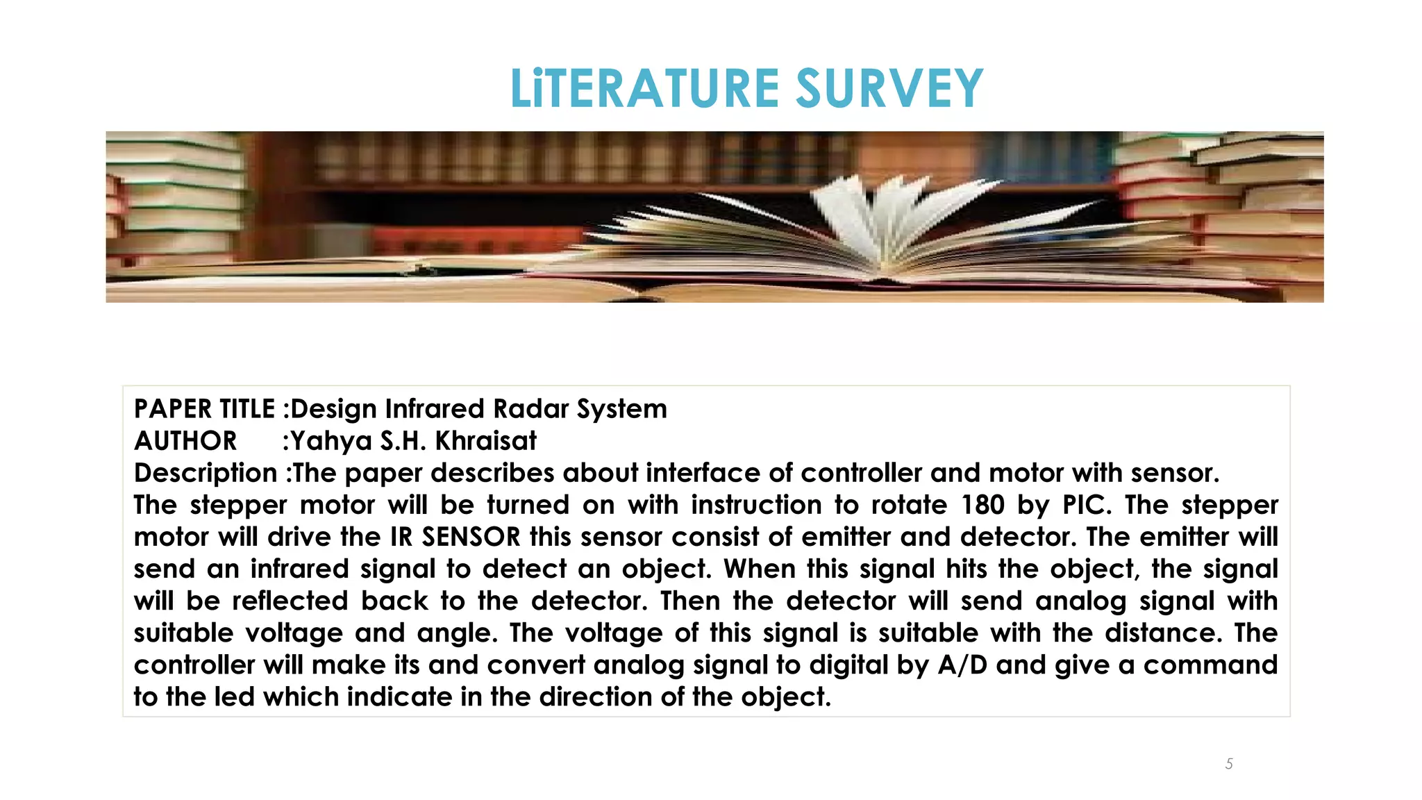
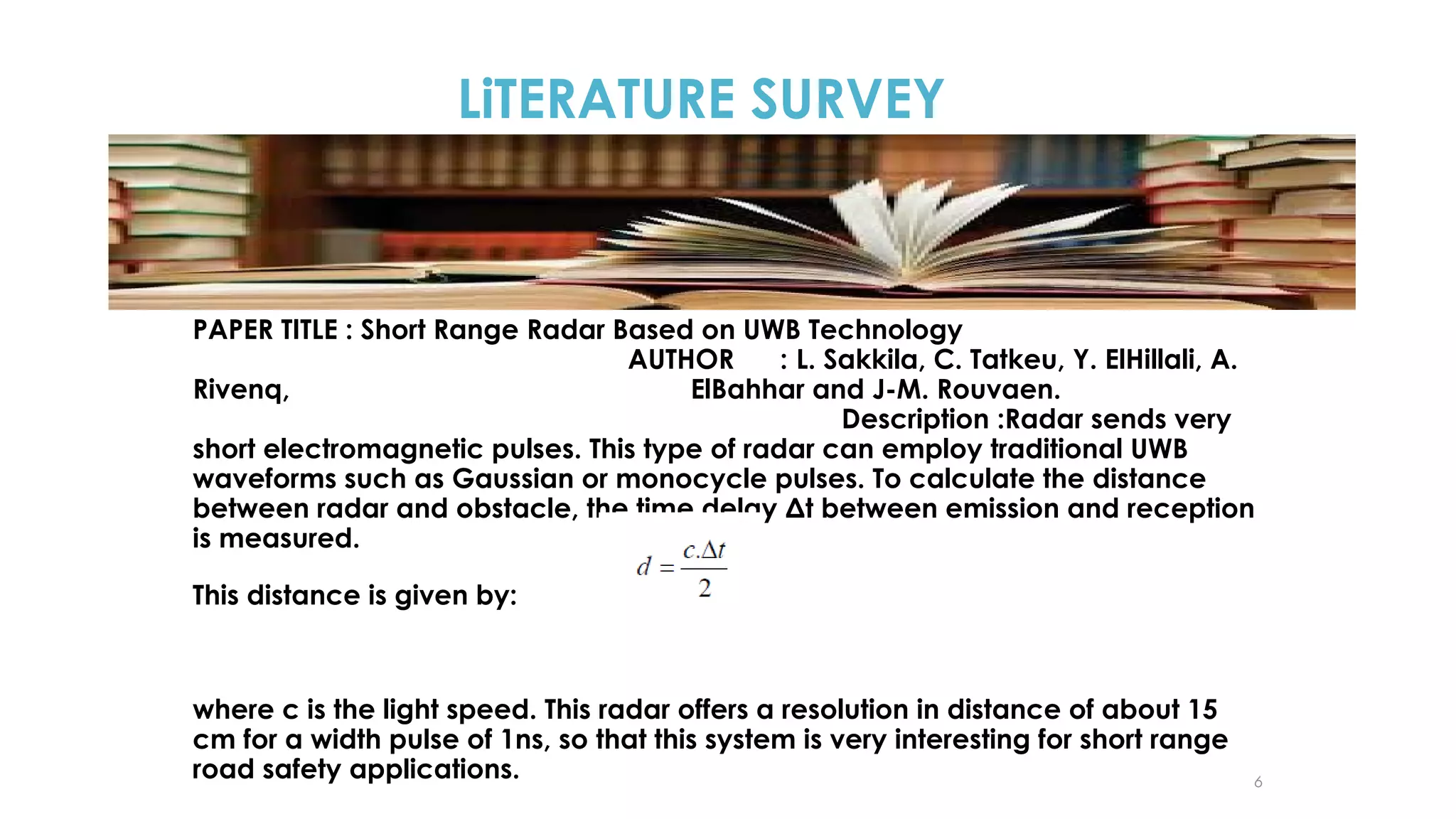
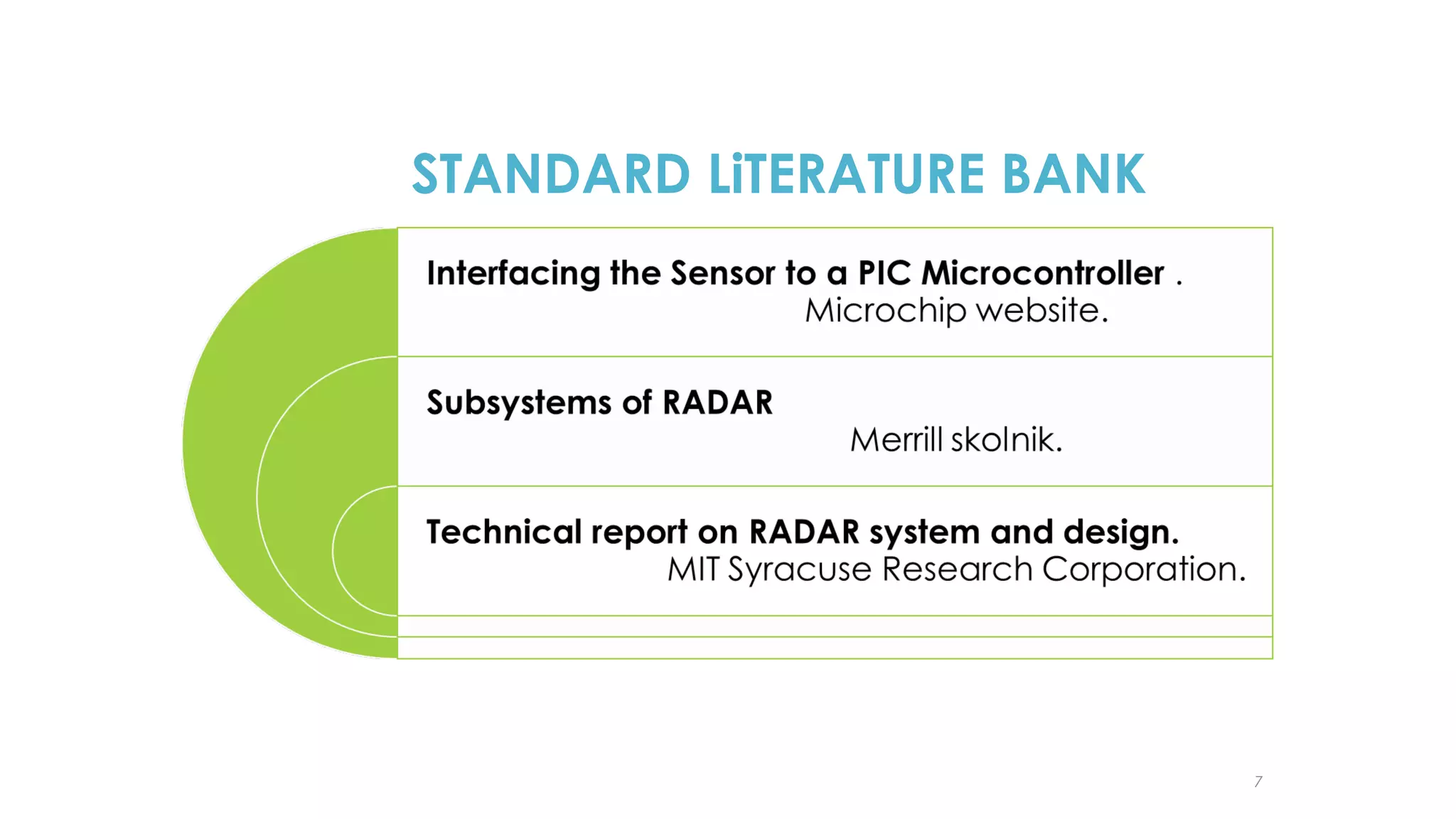
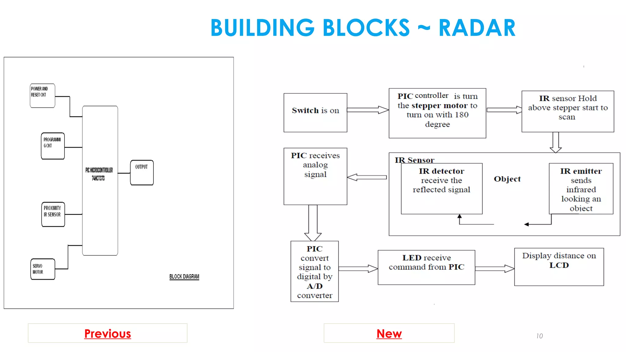
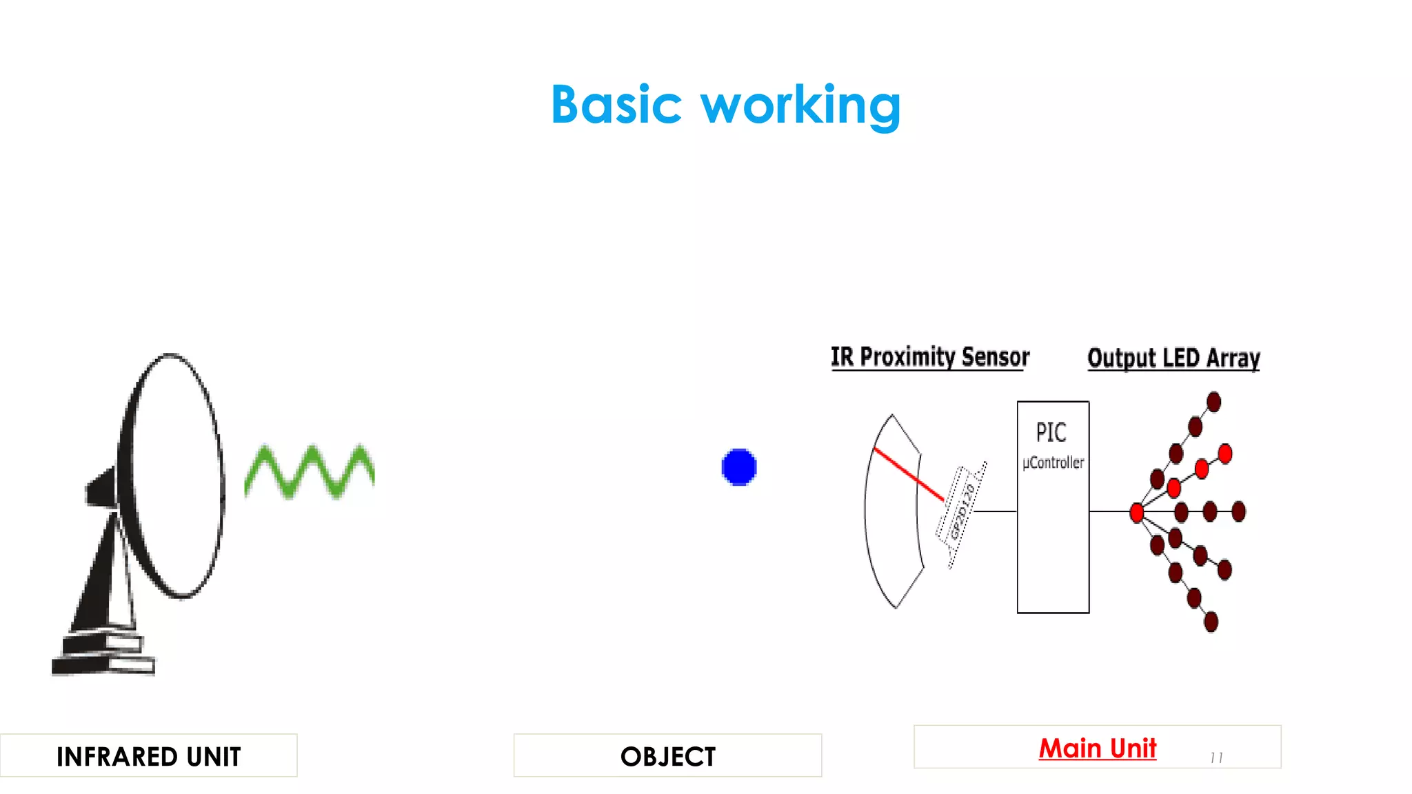
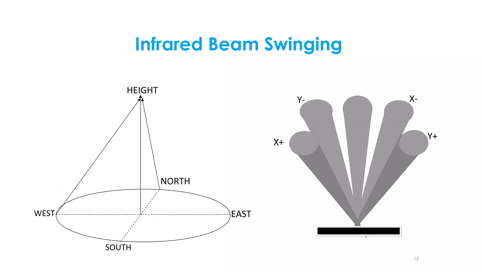

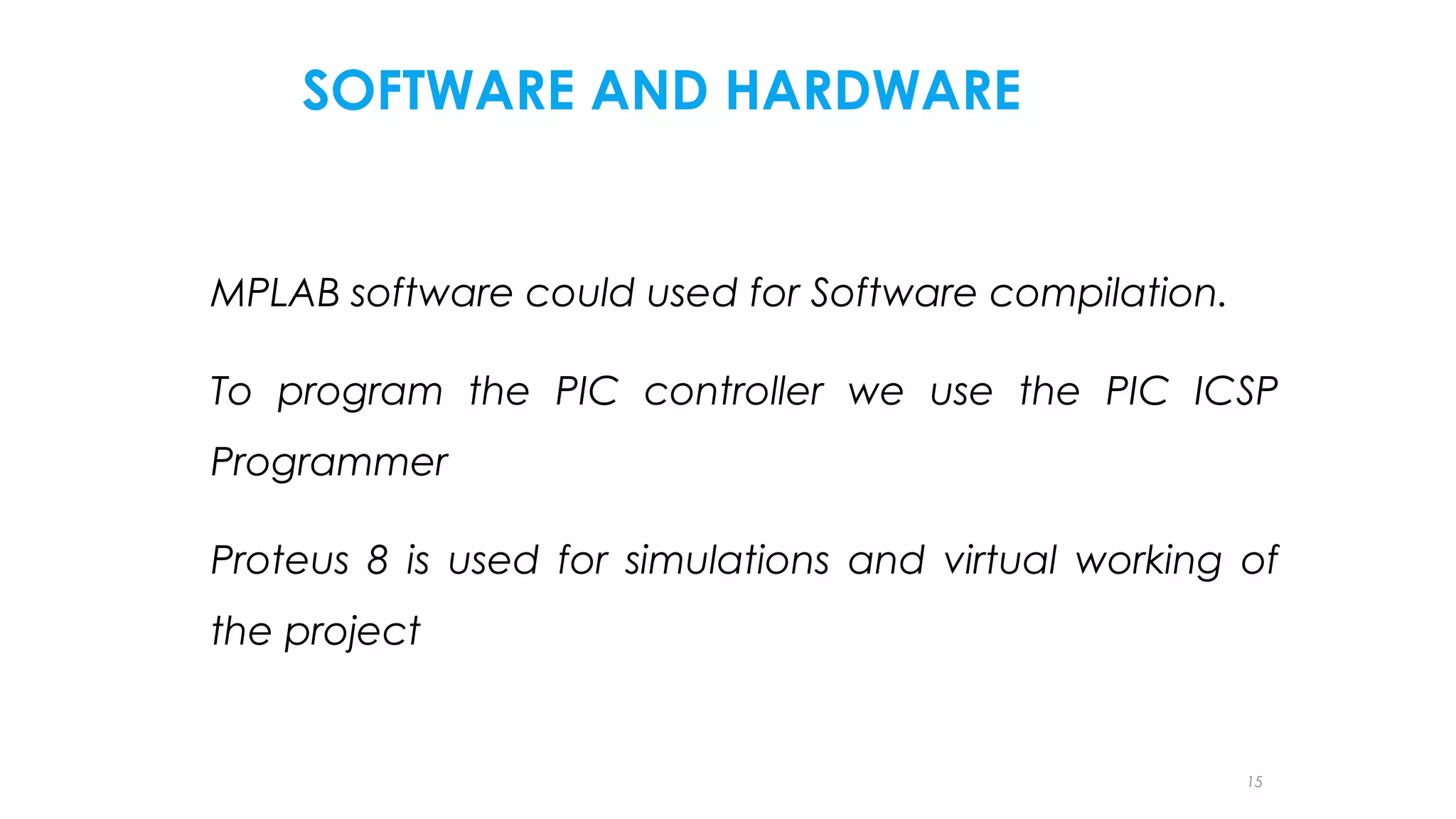
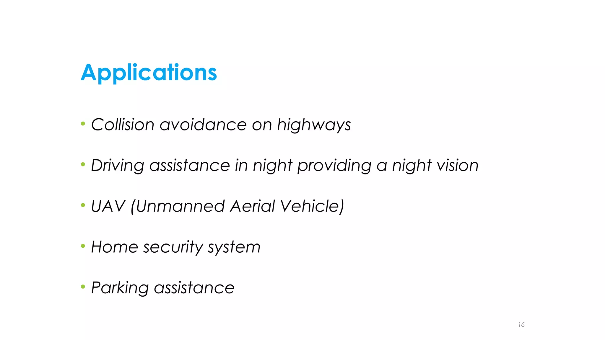
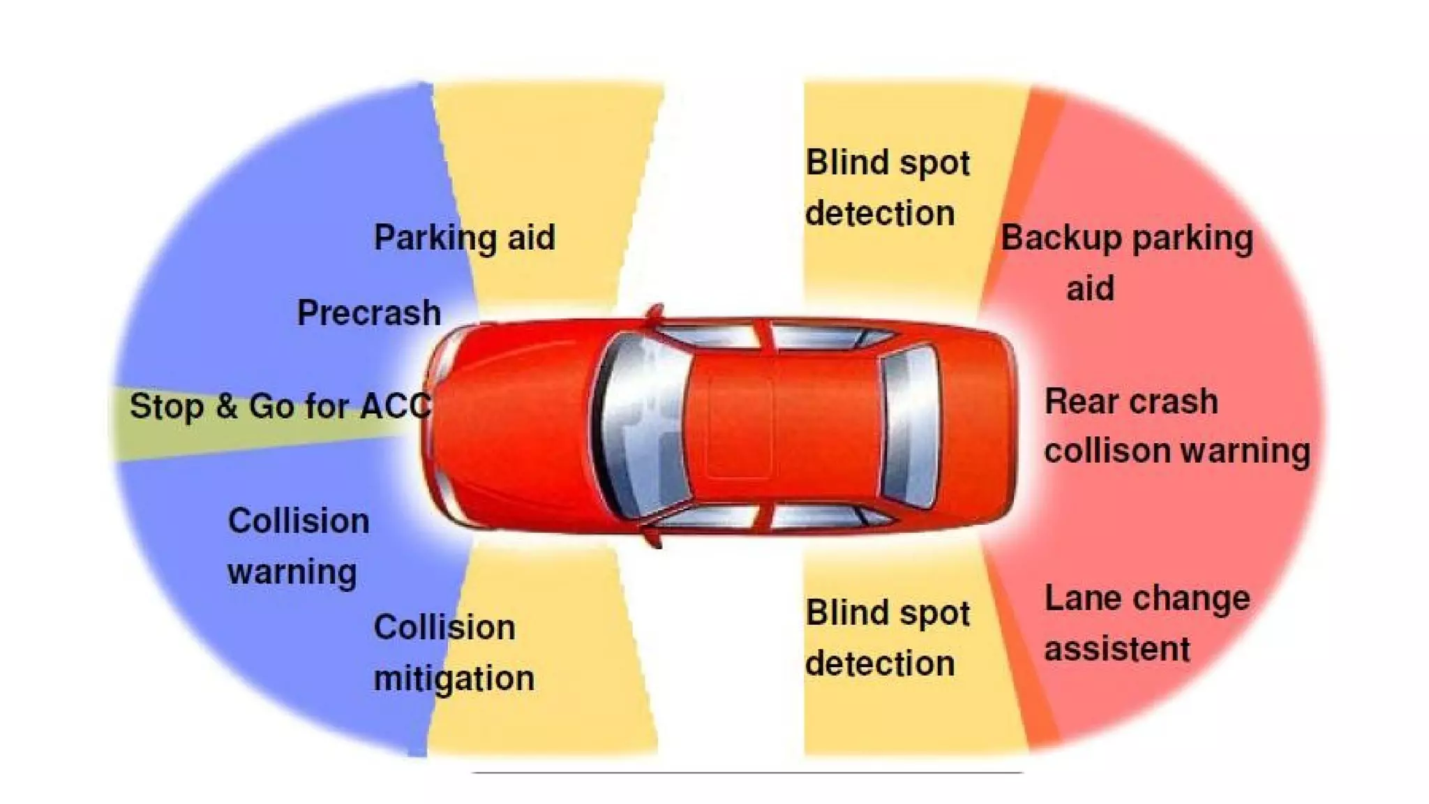


The document summarizes a student project to design a short range personal infrared radar system. The system will use an infrared sensor that rotates 180 degrees to detect objects from 10cm to 500cm away. When an object is detected, the microcontroller will activate an alarm sound and display the distance on an LCD screen. It will also illuminate an LED in the direction of the detected object. The students will survey literature on similar infrared and ultra-wideband radar systems and use software like MPLAB and Proteus to program the microcontroller and simulate the system. Potential applications include home security, parking assistance, and driving aids.