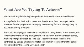
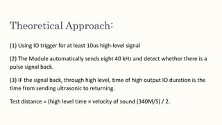
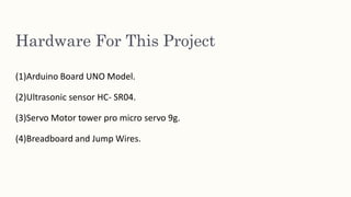
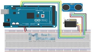
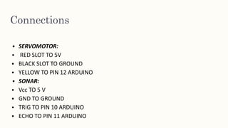
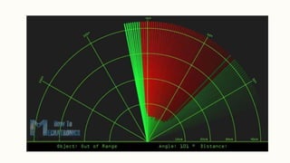
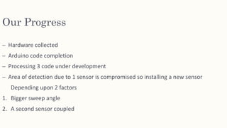
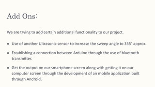
RADAR
DETECTOR
USING
ARDUINO
PROGRESS
REPORT
What Are We Trying To Achieve?
We are basically developing a rangefinder device which is explained below.
A rangefinder is a device that measures the distance from the target to the
observer, for the purposes of surveying, determining focus in photography, or
accurately aiming a weapon .
In this technical project, we make a simple radar using the ultrasonic sensor, this
radar works by measuring a range from 3cm to 40 cm as non-contact distance,
with angle range between 15˚ and 165˚.The movement of the sensor is
controlled by using a small servo motor. Information received from the sensor
will be used by “Processing Development E”
Theoretical Approach:
(1) Using IO trigger for at least 10us high-level signal
(2) The Module automatically sends eight 40 kHz and detect whether there is a
pulse signal back.
(3) IF the signal back, through high level, time of high output IO duration is the
time from sending ultrasonic to returning.
Test distance = (high level time × velocity of sound (340M/S) / 2.
Hardware For This Project
(1)Arduino Board UNO Model.
(2)Ultrasonic sensor HC- SR04.
(3)Servo Motor tower pro micro servo 9g.
(4)Breadboard and Jump Wires.
Software Used:
● ARDUINO IDE
● PREPROCESSING 3
Circuit Diagram
We connected the Ultrasonic Sensor HC-SR04 to the pins number 10 and 11 on
the Arduino Board.
TrigPin = 10.
EchoPin = 11.
And the servo motor to the pin number 12 on the Arduino Board.
Connections
• SERVOMOTOR:
• RED SLOT TO 5V
• BLACK SLOT TO GROUND
• YELLOW TO PIN 12 ARDUINO
• SONAR:
• Vcc TO 5 V
• GND TO GROUND
• TRIG TO PIN 10 ARDUINO
• ECHO TO PIN 11 ARDUINO
Arduino Ide:
• Ardunio uno micro controller board was connected with via standard Usb
cable.
• The program code were written in C complier based Ardunio Ide.
• Sensor and Motor input and output were assigned into the program.
PROCESSING 3:
• Serial output data of Ardunio contains present status of rotation angle and
measured distance by sensor in centimeter.
• These three serial output parameters were transferred to processing
environment software.
• With the help of java script coding a visual interface was developed and using
the serial o/p parameter from ardunio, real time visualization of the dual
radar was developed.
Arduino Code:
Processing 3 code
Our Progress
– Hardware collected
– Arduino code completion
– Processing 3 code under development
– Area of detection due to 1 sensor is compromised so installing a new sensor
Depending upon 2 factors
1. Bigger sweep angle
2. A second sensor coupled
Add Ons:
We are trying to add certain additional functionality to our project.
● Use of another Ultrasonic sensor to increase the sweep angle to 355˚ approx.
● Establishing a connection between Arduino through the use of bluetooth
transmitter.
● Get the output on our smartphone screen along with getting it on our
computer screen through the development of an mobile application built
through Android.
THANK YOU!

Radar Detector

  • 1.
  • 2.
    What Are WeTrying To Achieve? We are basically developing a rangefinder device which is explained below. A rangefinder is a device that measures the distance from the target to the observer, for the purposes of surveying, determining focus in photography, or accurately aiming a weapon . In this technical project, we make a simple radar using the ultrasonic sensor, this radar works by measuring a range from 3cm to 40 cm as non-contact distance, with angle range between 15˚ and 165˚.The movement of the sensor is controlled by using a small servo motor. Information received from the sensor will be used by “Processing Development E”
  • 3.
    Theoretical Approach: (1) UsingIO trigger for at least 10us high-level signal (2) The Module automatically sends eight 40 kHz and detect whether there is a pulse signal back. (3) IF the signal back, through high level, time of high output IO duration is the time from sending ultrasonic to returning. Test distance = (high level time × velocity of sound (340M/S) / 2.
  • 4.
    Hardware For ThisProject (1)Arduino Board UNO Model. (2)Ultrasonic sensor HC- SR04. (3)Servo Motor tower pro micro servo 9g. (4)Breadboard and Jump Wires.
  • 5.
    Software Used: ● ARDUINOIDE ● PREPROCESSING 3
  • 6.
    Circuit Diagram We connectedthe Ultrasonic Sensor HC-SR04 to the pins number 10 and 11 on the Arduino Board. TrigPin = 10. EchoPin = 11. And the servo motor to the pin number 12 on the Arduino Board.
  • 8.
    Connections • SERVOMOTOR: • REDSLOT TO 5V • BLACK SLOT TO GROUND • YELLOW TO PIN 12 ARDUINO • SONAR: • Vcc TO 5 V • GND TO GROUND • TRIG TO PIN 10 ARDUINO • ECHO TO PIN 11 ARDUINO
  • 9.
    Arduino Ide: • Arduniouno micro controller board was connected with via standard Usb cable. • The program code were written in C complier based Ardunio Ide. • Sensor and Motor input and output were assigned into the program.
  • 10.
    PROCESSING 3: • Serialoutput data of Ardunio contains present status of rotation angle and measured distance by sensor in centimeter. • These three serial output parameters were transferred to processing environment software. • With the help of java script coding a visual interface was developed and using the serial o/p parameter from ardunio, real time visualization of the dual radar was developed.
  • 11.
  • 13.
  • 16.
    Our Progress – Hardwarecollected – Arduino code completion – Processing 3 code under development – Area of detection due to 1 sensor is compromised so installing a new sensor Depending upon 2 factors 1. Bigger sweep angle 2. A second sensor coupled
  • 17.
    Add Ons: We aretrying to add certain additional functionality to our project. ● Use of another Ultrasonic sensor to increase the sweep angle to 355˚ approx. ● Establishing a connection between Arduino through the use of bluetooth transmitter. ● Get the output on our smartphone screen along with getting it on our computer screen through the development of an mobile application built through Android.
  • 18.