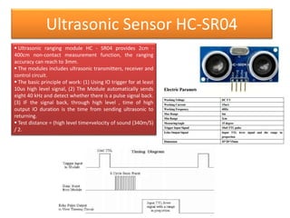
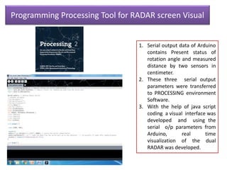
Design of Ultrasonic Sensor
Based RADAR
CONTENTS:-
• INTRODUCTION OF RADAR TECHNOLOGY
• COMPONENTS REQUIRED
• SG 90 –SERVO METER
• ULTRASONIC SENSOR HC SR04
• EXPERIMENTAL PROCESS FLOW
• DESIGN OF ULTRASONIC RADAR
• APPLICATIONS OF RADAR
Introduction
• RADAR is short form of Radio Detection and
Ranging. It uses radio waves. It has trasmitter
which transmits radio waves and waves gets
reflected back to receiver which processes
data and calculates position , distance, speed
of target.
• In this prototype , instead of radio waves , we
are using sound waves. Here, ultrasonic sensor
is used which has range of only 4 meters.
Technically this is not RADAR, it is SONAR
(Sound Navigation and Ranging)
Components Required
Arduino
UNO Board
HC-SR04
Ultrasonic sensor
SG-90 Micro-
Servo motor
ARDUINO UNO
• The Arduino uno is a
microcontroller board
based on the ATmega328.
• It has 14 digital Input /
Output pins (of which 6
can be used as PWM
outputs), 6 analog inputs,
a 16MHz ceramic
resonator, USB connection,
a power jack, an ICSP
header and a reset button.
• It contains everything
needed to support the
microcontroller; simply
connect it to computer
with a USB cable or power
it with a AC-to-DC adapter
or battery to get started.
SG-90 SERVO MOTOR
• A servomotor is a rotary
actuator that allows for
precise control of angular
position, velocity and
acceleration.
• It consists of a suitable motor
coupled to a sensor for
position feedback.
• Servomotors are used in
applications such
as robotics, CNC machinery or
automated manufacturing.
Ultrasonic Sensor HC-SR04
 Ultrasonic ranging module HC - SR04 provides 2cm -
400cm non-contact measurement function, the ranging
accuracy can reach to 3mm.
 The modules includes ultrasonic transmitters, receiver and
control circuit.
 The basic principle of work: (1) Using IO trigger for at least
10us high level signal, (2) The Module automatically sends
eight 40 kHz and detect whether there is a pulse signal back.
(3) IF the signal back, through high level , time of high
output IO duration is the time from sending ultrasonic to
returning.
 Test distance = (high level time×velocity of sound (340m/S)
/ 2.
Experimental-process flow
• Design of Ultrasonic RADAR antenna.
• Design of rotating mechanism for antenna.
• Implementation of trans-receiver program
with Arduino UNO microcontroller.
• Visual output of the RADAR in screen with
PROCESSING Software.
• Assembling all the electronic parts in plastic
case.
Arduino Connections
Arduino IDE (Compiler)
Programming Processing Tool for RADAR screen Visual
1. Serial output data of Arduino
contains Present status of
rotation angle and measured
distance by two sensors in
centimeter.
2. These three serial output
parameters were transferred
to PROCESSING environment
Software.
3. With the help of java script
coding a visual interface was
developed and using the
serial o/p parameters from
Arduino, real time
visualization of the dual
RADAR was developed.
Final Resuts of RADAR Prototype
RADAR Design RADAR screen Processing Tool Output
Radar
Radar
Radar
Radar

Radar

  • 1.
    Design of UltrasonicSensor Based RADAR
  • 2.
    CONTENTS:- • INTRODUCTION OFRADAR TECHNOLOGY • COMPONENTS REQUIRED • SG 90 –SERVO METER • ULTRASONIC SENSOR HC SR04 • EXPERIMENTAL PROCESS FLOW • DESIGN OF ULTRASONIC RADAR • APPLICATIONS OF RADAR
  • 3.
    Introduction • RADAR isshort form of Radio Detection and Ranging. It uses radio waves. It has trasmitter which transmits radio waves and waves gets reflected back to receiver which processes data and calculates position , distance, speed of target. • In this prototype , instead of radio waves , we are using sound waves. Here, ultrasonic sensor is used which has range of only 4 meters. Technically this is not RADAR, it is SONAR (Sound Navigation and Ranging)
  • 4.
  • 5.
    ARDUINO UNO • TheArduino uno is a microcontroller board based on the ATmega328. • It has 14 digital Input / Output pins (of which 6 can be used as PWM outputs), 6 analog inputs, a 16MHz ceramic resonator, USB connection, a power jack, an ICSP header and a reset button. • It contains everything needed to support the microcontroller; simply connect it to computer with a USB cable or power it with a AC-to-DC adapter or battery to get started.
  • 6.
    SG-90 SERVO MOTOR •A servomotor is a rotary actuator that allows for precise control of angular position, velocity and acceleration. • It consists of a suitable motor coupled to a sensor for position feedback. • Servomotors are used in applications such as robotics, CNC machinery or automated manufacturing.
  • 7.
    Ultrasonic Sensor HC-SR04 Ultrasonic ranging module HC - SR04 provides 2cm - 400cm non-contact measurement function, the ranging accuracy can reach to 3mm.  The modules includes ultrasonic transmitters, receiver and control circuit.  The basic principle of work: (1) Using IO trigger for at least 10us high level signal, (2) The Module automatically sends eight 40 kHz and detect whether there is a pulse signal back. (3) IF the signal back, through high level , time of high output IO duration is the time from sending ultrasonic to returning.  Test distance = (high level time×velocity of sound (340m/S) / 2.
  • 8.
    Experimental-process flow • Designof Ultrasonic RADAR antenna. • Design of rotating mechanism for antenna. • Implementation of trans-receiver program with Arduino UNO microcontroller. • Visual output of the RADAR in screen with PROCESSING Software. • Assembling all the electronic parts in plastic case.
  • 9.
  • 10.
  • 11.
    Programming Processing Toolfor RADAR screen Visual 1. Serial output data of Arduino contains Present status of rotation angle and measured distance by two sensors in centimeter. 2. These three serial output parameters were transferred to PROCESSING environment Software. 3. With the help of java script coding a visual interface was developed and using the serial o/p parameters from Arduino, real time visualization of the dual RADAR was developed.
  • 12.
    Final Resuts ofRADAR Prototype RADAR Design RADAR screen Processing Tool Output