![DIGITAL BCD COUNTER IMPLEMENTATION 5
Frequency, f = 1.44/[(R1+R2)C]
Duty cycle = [(R1+R2)/(R1+2R2)]x 100%](https://image.slidesharecdn.com/projectbcddld-140503235104-phpapp01/75/a-simple-bcd-counter-project-6-2048.jpg)
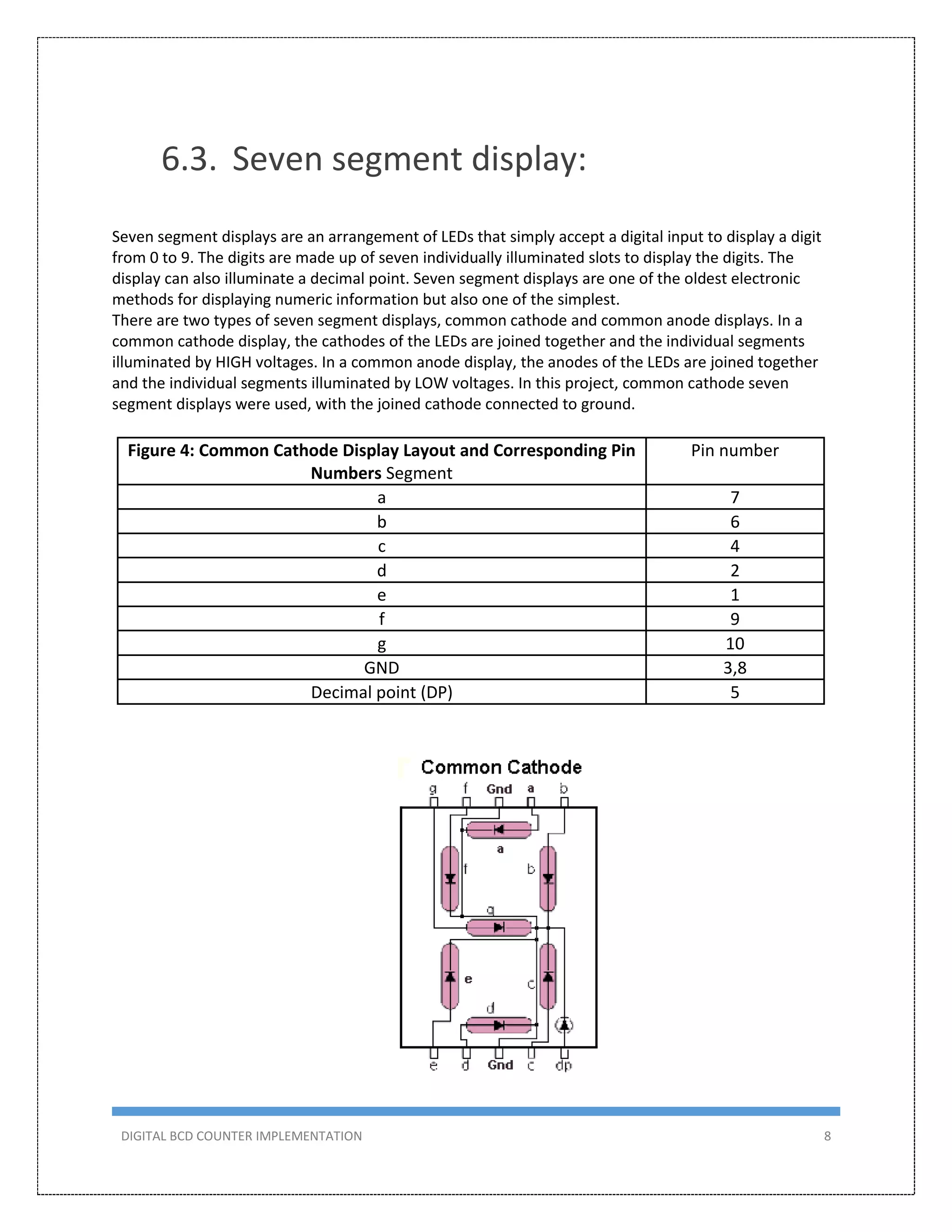
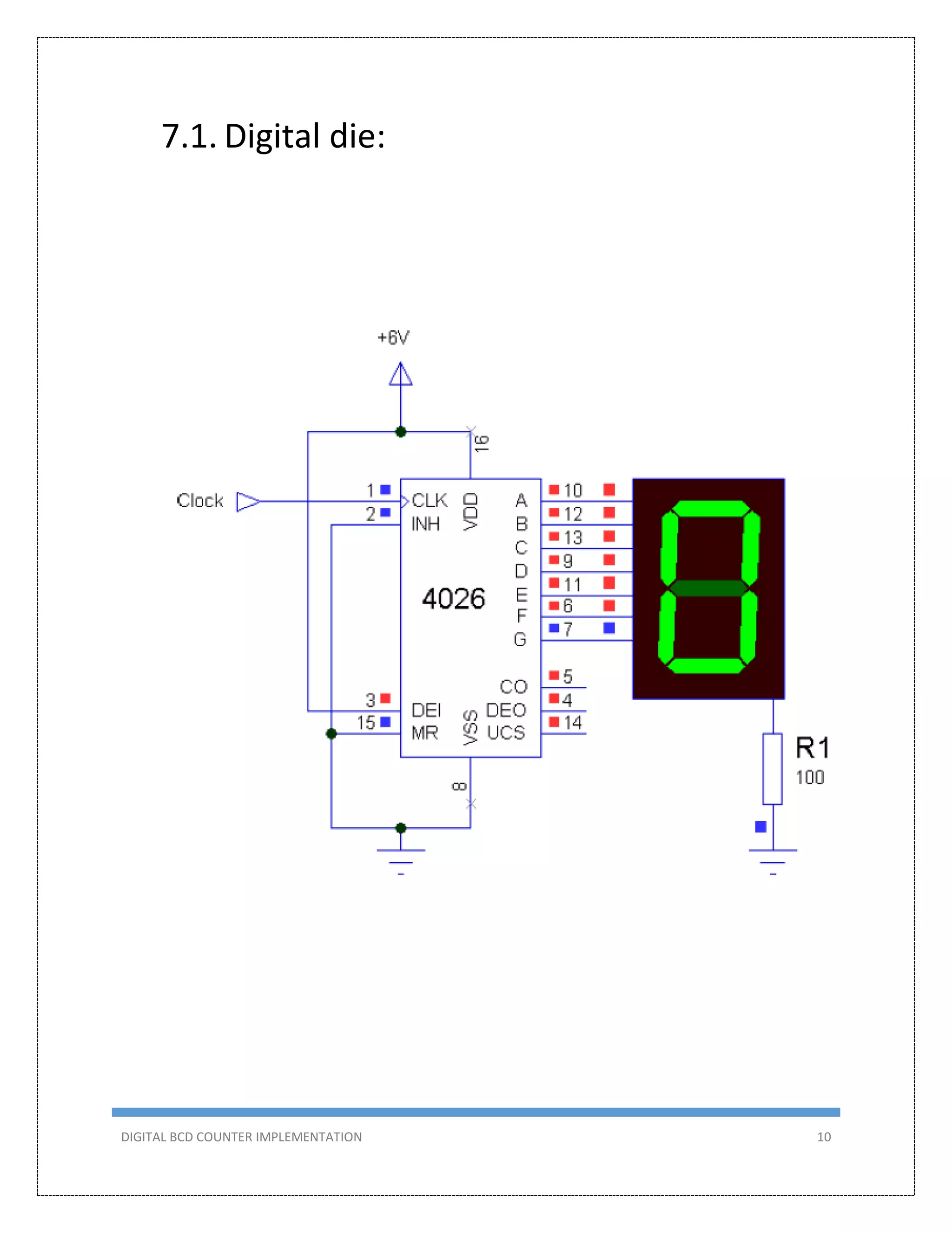
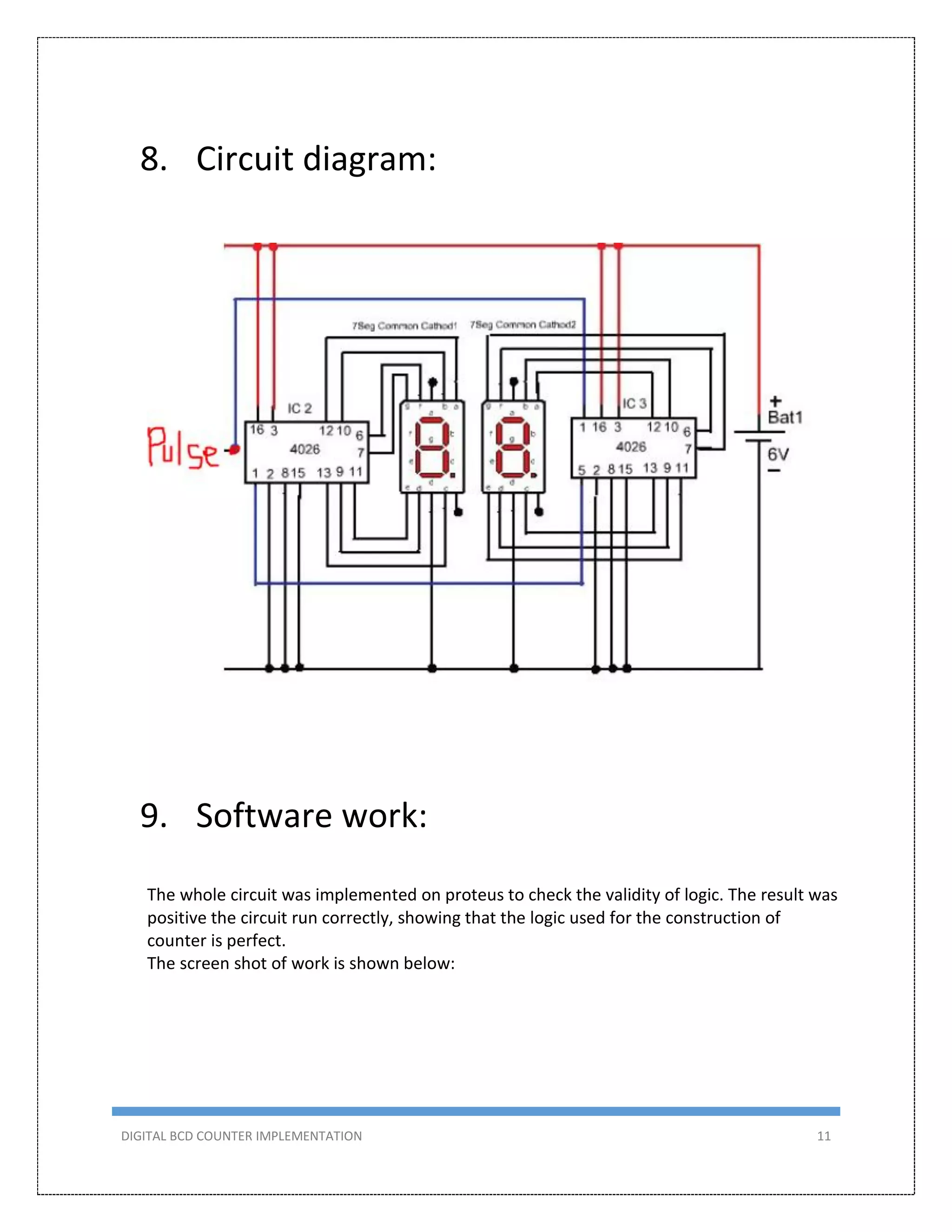
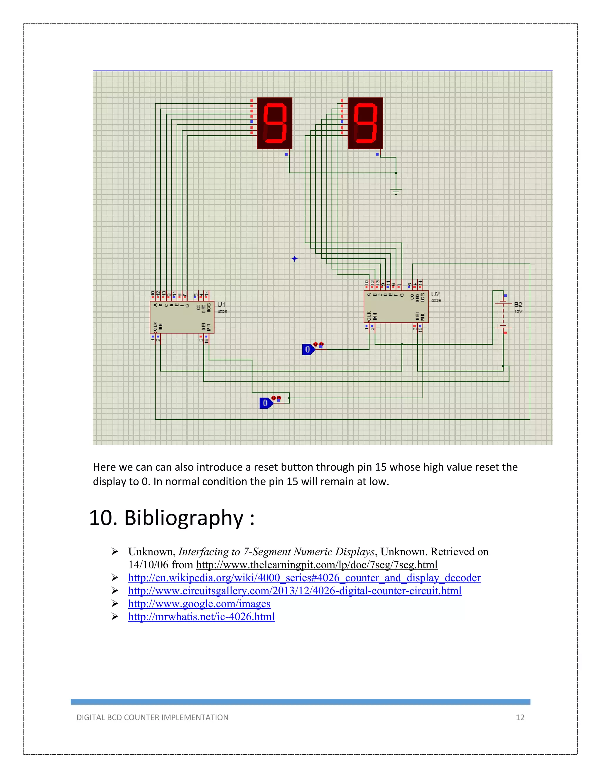

This document describes the design and implementation of a 0-99 digital BCD counter circuit. The circuit uses a 4026 IC and 7-segment displays to display the count. It can operate in two modes - manually using a switch or automatically using a 555 timer as a clock. The circuit was designed, simulated in Proteus, built on a breadboard, and tested to meet the criteria of counting from 0-99 on two displays.


![[Project report]digital speedometer with password enabled speed controlling(1...](https://cdn.slidesharecdn.com/ss_thumbnails/projectreportdigitalspeedometerwithpasswordenabledspeedcontrolling1dip-151005065229-lva1-app6891-thumbnail.jpg?width=640&height=640&fit=bounds)