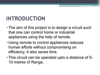
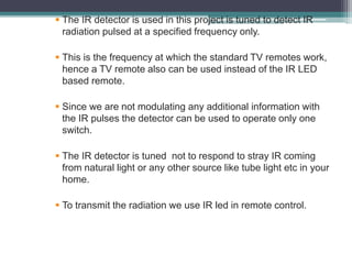
INFRARED
REMOTE CONTROL SWITCH
SUBMITTED BY:--
VIVEK PORWAL
BBDNITM,LKO
ROLL:-1305421125
iNTRODUCTiON
The aim of this project is to design a circuit such
that one can control home or industrial
appliances using the help of remote.
Using remote to control appliances reduces
human efforts without compromising on
efficiency. It also saves time.
This circuit can be operated upto a distance of 5-
10 metres of Range.
REQUIREMENTS
• 5V Regulator 7805 (IC)
• BC547 (NPN Transistor)
• BC558 (PNP Transistor)
• RELAY
• TSOP 1738 (IR Remote Control receiver)
• RESISTANCES
• CAPACITORS(0.1 mF,100mF)
• CD 4017 (COUNTER IC)
THE CIRCUIT
WORKING
 Home appliance is controlled either by pressing any key on the
remote.
 The circuit works on regulated 5V which is obtained from regulated
by IC7805.
 The TV/DVD remote controller produces 38kHz frequency.
 IR RECEIVER MODULE: The IR receiver module operates at this
frequency(38kHz).
 The relay triggers IC CD4017, which is wired in a bi-stable mode to
control the home appliance connected at the contacts of Relay.
 CD4017 IC:CD4017BM/CD4017BC is a 5-stage
divide-by-10 Johnson counter with 10 decoded
outputs and a carry out bit.
 The 10 decoded outputs are normally in the logical
``0'' state and go to the logical ``1'' state only at
their respective time slot.
 IR receiver module (TSOP1738) :
At normal condition, when IR rays are not incident
on TSOP1738, its output at pin 3 remains high.
When any TV remote key is pressed, IR rays fall on
the TSOP1738 and its output goes low.
ACTUAL CIRCUIT
 The IR detector is used in this project is tuned to detect IR
radiation pulsed at a specified frequency only.
 This is the frequency at which the standard TV remotes work,
hence a TV remote also can be used instead of the IR LED
based remote.
 Since we are not modulating any additional information with
the IR pulses the detector can be used to operate only one
switch..
 The IR detector is tuned not to respond to stray IR coming
from natural light or any other source like tube light etc in your
home.
 To transmit the radiation we use IR led in remote control.
APPLICATIONS
 This system can be used in industrial applications.
 This system reduces human efforts and makes life a bit easy
without compromising on the efficiency of appliances.
 Using this system one can also save time.
ADVANTAGES
 Portable and easy to use.
 Simple in construction.
 Easy to maintain and repair.
 Efficient and low cost design.
 Low power consumption.
THANKS
!

Infrared Remote Control Switch

  • 1.
    INFRARED REMOTE CONTROL SWITCH SUBMITTEDBY:-- VIVEK PORWAL BBDNITM,LKO ROLL:-1305421125
  • 2.
    iNTRODUCTiON The aim ofthis project is to design a circuit such that one can control home or industrial appliances using the help of remote. Using remote to control appliances reduces human efforts without compromising on efficiency. It also saves time. This circuit can be operated upto a distance of 5- 10 metres of Range.
  • 3.
    REQUIREMENTS • 5V Regulator7805 (IC) • BC547 (NPN Transistor) • BC558 (PNP Transistor) • RELAY • TSOP 1738 (IR Remote Control receiver) • RESISTANCES • CAPACITORS(0.1 mF,100mF) • CD 4017 (COUNTER IC)
  • 4.
  • 5.
    WORKING  Home applianceis controlled either by pressing any key on the remote.  The circuit works on regulated 5V which is obtained from regulated by IC7805.  The TV/DVD remote controller produces 38kHz frequency.  IR RECEIVER MODULE: The IR receiver module operates at this frequency(38kHz).  The relay triggers IC CD4017, which is wired in a bi-stable mode to control the home appliance connected at the contacts of Relay.
  • 6.
     CD4017 IC:CD4017BM/CD4017BCis a 5-stage divide-by-10 Johnson counter with 10 decoded outputs and a carry out bit.  The 10 decoded outputs are normally in the logical ``0'' state and go to the logical ``1'' state only at their respective time slot.  IR receiver module (TSOP1738) : At normal condition, when IR rays are not incident on TSOP1738, its output at pin 3 remains high. When any TV remote key is pressed, IR rays fall on the TSOP1738 and its output goes low.
  • 7.
  • 8.
     The IRdetector is used in this project is tuned to detect IR radiation pulsed at a specified frequency only.  This is the frequency at which the standard TV remotes work, hence a TV remote also can be used instead of the IR LED based remote.  Since we are not modulating any additional information with the IR pulses the detector can be used to operate only one switch..  The IR detector is tuned not to respond to stray IR coming from natural light or any other source like tube light etc in your home.  To transmit the radiation we use IR led in remote control.
  • 9.
    APPLICATIONS  This systemcan be used in industrial applications.  This system reduces human efforts and makes life a bit easy without compromising on the efficiency of appliances.  Using this system one can also save time. ADVANTAGES  Portable and easy to use.  Simple in construction.  Easy to maintain and repair.  Efficient and low cost design.  Low power consumption.
  • 10.