Download to read offline


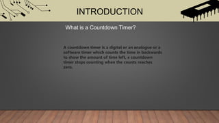
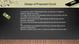
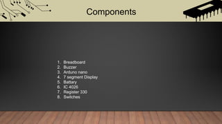
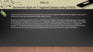


This document provides details on designing and building a countdown timer circuit using a 7-segment display and IC 4026 chips. It includes: - An overview of the components used, including a breadboard, buzzer, Arduino Nano, 7-segment display, battery, IC 4026 chips, and switches. - A description of how the IC 4026 chips will be used with the 7-segment display to count minutes and seconds backwards from a set time. - An explanation of how the Arduino will control the reset and clock pins of the IC 4026 chips to quickly decrement the displayed numbers and create a countdown effect.


![Getting Started with Apache Spark: Big Data Made Simple [Free Meetup]](https://cdn.slidesharecdn.com/ss_thumbnails/apachesparkgettingstarted-260203175547-8361bcc3-thumbnail.jpg?width=640&height=640&fit=bounds)


