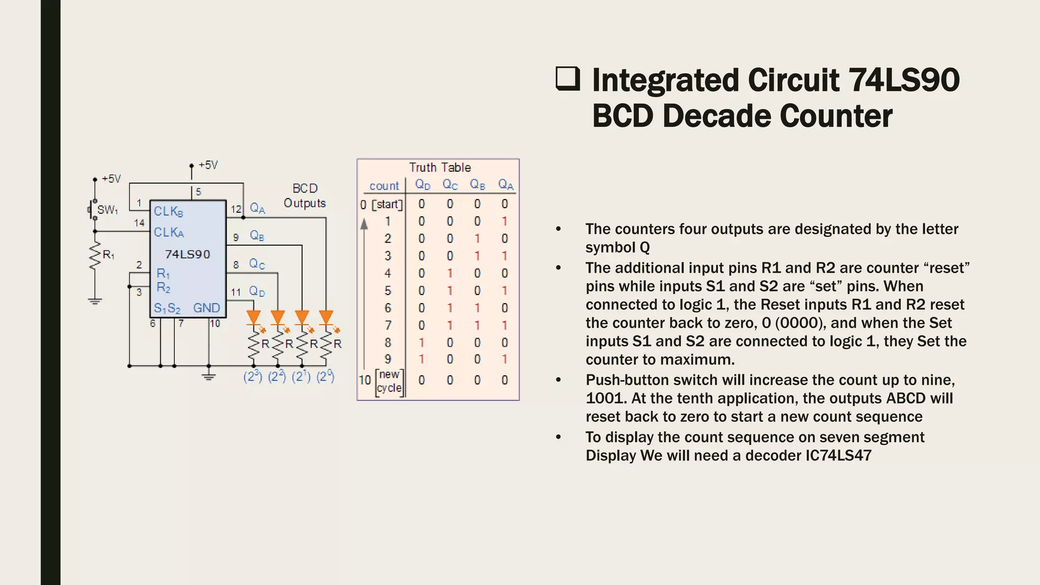
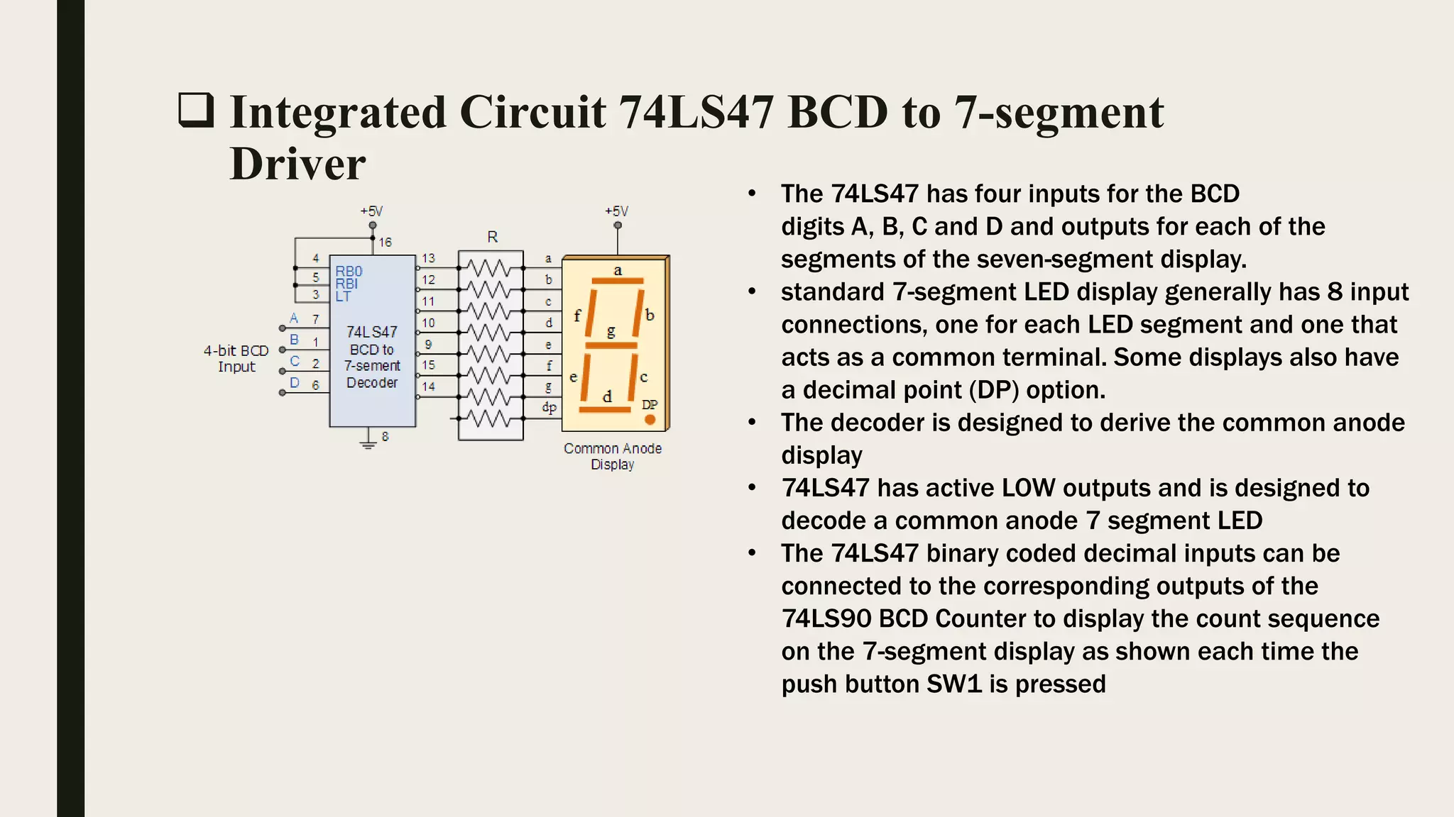
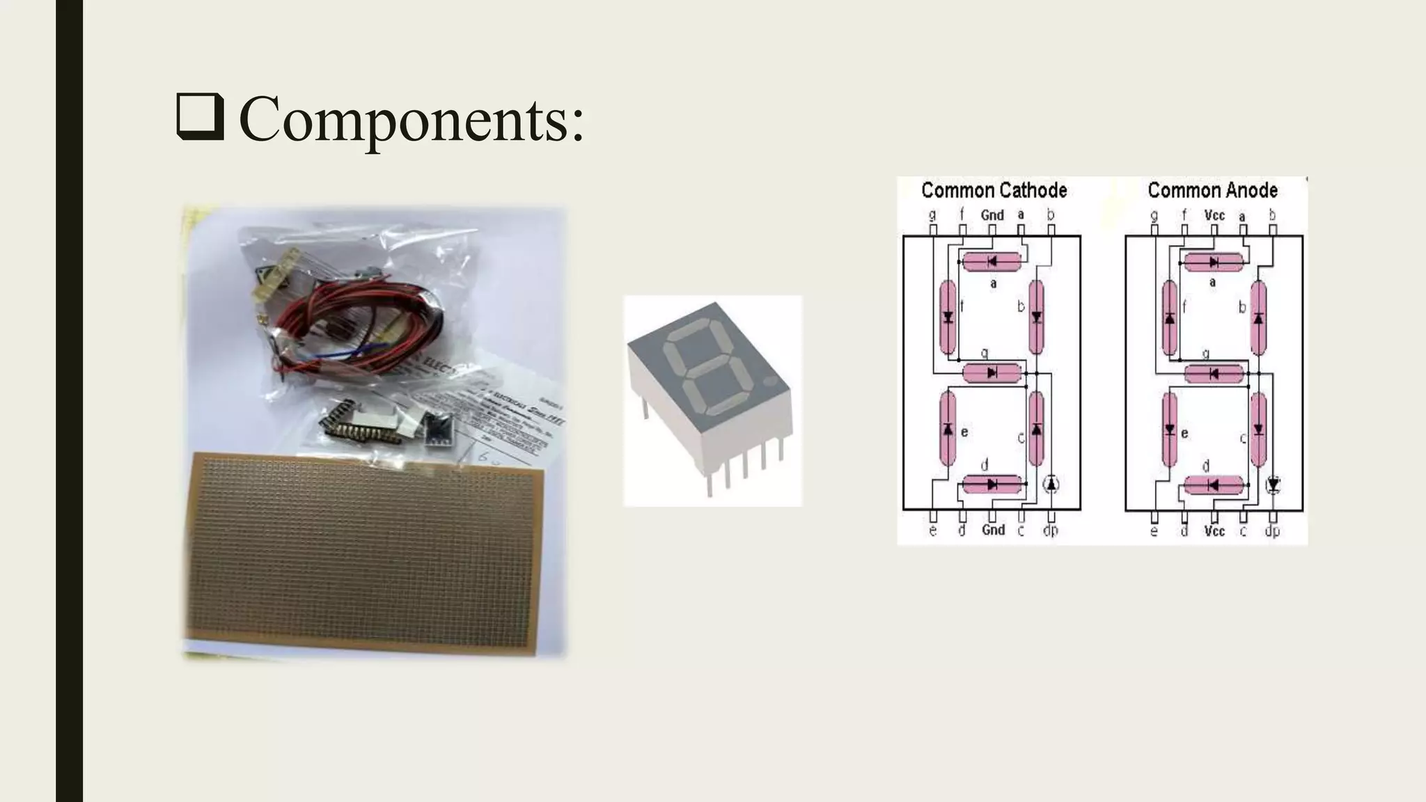
Digital Systems and Applications
By:
Rohit Mane SETB102
Abhishek Sainkar SETB104
Omkar Rane SETB118
Kaustubh Wankhede SETB131
0-9 Binary Coded Digit Counter.
Introduction:
Objective: To design 0-9 BCD Counter Circuit
• Then a decade counter has four flip-flops and 16
potential states
• The total number of counts that a counter can count
too is called its MODULUS. A counter that returns
to zero after n counts is called a modulo-n counter
• It is called a BCD counter because its ten-state
sequence is that of a BCD code and does not have a
regular pattern
 Integrated Circuit 74LS90
BCD Decade Counter
• The counters four outputs are designated by the letter
symbol Q
• The additional input pins R1 and R2 are counter “reset”
pins while inputs S1 and S2 are “set” pins. When
connected to logic 1, the Reset inputs R1 and R2 reset
the counter back to zero, 0 (0000), and when the Set
inputs S1 and S2 are connected to logic 1, they Set the
counter to maximum.
• Push-button switch will increase the count up to nine,
1001. At the tenth application, the outputs ABCD will
reset back to zero to start a new count sequence
• To display the count sequence on seven segment
Display We will need a decoder IC74LS47
 Integrated Circuit 74LS47 BCD to 7-segment
Driver • The 74LS47 has four inputs for the BCD
digits A, B, C and D and outputs for each of the
segments of the seven-segment display.
• standard 7-segment LED display generally has 8 input
connections, one for each LED segment and one that
acts as a common terminal. Some displays also have
a decimal point (DP) option.
• The decoder is designed to derive the common anode
display
• 74LS47 has active LOW outputs and is designed to
decode a common anode 7 segment LED
• The 74LS47 binary coded decimal inputs can be
connected to the corresponding outputs of the
74LS90 BCD Counter to display the count sequence
on the 7-segment display as shown each time the
push button SW1 is pressed
Components:
Design:
Bread board Implementation Circuit Diagram
Working Of Counter:
 Digital Work Simulation
Application:
• Bank Token Counters at cashier section.
• Counting system on automated production line.
• Digital Clocks
• Digital stop watches.
• Timers for automated water supply .
• Sensor controlled counters.
• Counting general objects in a any system
Advantages Disadvantages
• More Number of counters can
be increased by increasing
number of counter IC and 7
segment displays.
• Cascading ensures that value
of counter can be increased or
decreased as per applications
and use.
• Counter Circuit can be used
with other circuits to perform
automated control actions.
• As the number of counter size
increases the complexity of building
circuit also increases.
• Cost also increases because the use
of more ICs and 7 segments takes
place.
Further:
• We Can improve our
existing design by
making changes by
cascading more
counter IC and 7
segment displays.
References:
■ http://www.electronics-tutorials.ws/counter/bcd-counter-circuit.html
■ https://youtu.be/fU6sMNam2yM
■ https://youtu.be/InvaoZduE4g
■ https://youtu.be/2n7nM001Oi4
■ http://www.electronicshub.org/decade-counterbcd-counter/
■ Texas Instruments Datasheets IC 74LS90 and IC 74LS47
■ http://www.daenotes.com/electronics/digital-electronics/counters-types-of-counters
■ https://en.wikipedia.org/wiki/Binary-coded_decimal
■
THANKYOU!

decade counter

  • 1.
    Digital Systems andApplications By: Rohit Mane SETB102 Abhishek Sainkar SETB104 Omkar Rane SETB118 Kaustubh Wankhede SETB131 0-9 Binary Coded Digit Counter.
  • 2.
    Introduction: Objective: To design0-9 BCD Counter Circuit • Then a decade counter has four flip-flops and 16 potential states • The total number of counts that a counter can count too is called its MODULUS. A counter that returns to zero after n counts is called a modulo-n counter • It is called a BCD counter because its ten-state sequence is that of a BCD code and does not have a regular pattern
  • 3.
     Integrated Circuit74LS90 BCD Decade Counter • The counters four outputs are designated by the letter symbol Q • The additional input pins R1 and R2 are counter “reset” pins while inputs S1 and S2 are “set” pins. When connected to logic 1, the Reset inputs R1 and R2 reset the counter back to zero, 0 (0000), and when the Set inputs S1 and S2 are connected to logic 1, they Set the counter to maximum. • Push-button switch will increase the count up to nine, 1001. At the tenth application, the outputs ABCD will reset back to zero to start a new count sequence • To display the count sequence on seven segment Display We will need a decoder IC74LS47
  • 4.
     Integrated Circuit74LS47 BCD to 7-segment Driver • The 74LS47 has four inputs for the BCD digits A, B, C and D and outputs for each of the segments of the seven-segment display. • standard 7-segment LED display generally has 8 input connections, one for each LED segment and one that acts as a common terminal. Some displays also have a decimal point (DP) option. • The decoder is designed to derive the common anode display • 74LS47 has active LOW outputs and is designed to decode a common anode 7 segment LED • The 74LS47 binary coded decimal inputs can be connected to the corresponding outputs of the 74LS90 BCD Counter to display the count sequence on the 7-segment display as shown each time the push button SW1 is pressed
  • 5.
  • 6.
  • 7.
  • 8.
     Digital WorkSimulation
  • 9.
    Application: • Bank TokenCounters at cashier section. • Counting system on automated production line. • Digital Clocks • Digital stop watches. • Timers for automated water supply . • Sensor controlled counters. • Counting general objects in a any system
  • 10.
    Advantages Disadvantages • MoreNumber of counters can be increased by increasing number of counter IC and 7 segment displays. • Cascading ensures that value of counter can be increased or decreased as per applications and use. • Counter Circuit can be used with other circuits to perform automated control actions. • As the number of counter size increases the complexity of building circuit also increases. • Cost also increases because the use of more ICs and 7 segments takes place.
  • 11.
    Further: • We Canimprove our existing design by making changes by cascading more counter IC and 7 segment displays.
  • 12.
    References: ■ http://www.electronics-tutorials.ws/counter/bcd-counter-circuit.html ■ https://youtu.be/fU6sMNam2yM ■https://youtu.be/InvaoZduE4g ■ https://youtu.be/2n7nM001Oi4 ■ http://www.electronicshub.org/decade-counterbcd-counter/ ■ Texas Instruments Datasheets IC 74LS90 and IC 74LS47 ■ http://www.daenotes.com/electronics/digital-electronics/counters-types-of-counters ■ https://en.wikipedia.org/wiki/Binary-coded_decimal ■
  • 13.