Downloaded 690 times
![CONTENTS
1. Aim
2. Components
3. Circuit description (proposed)
i. Pulse generator
ii. Counter
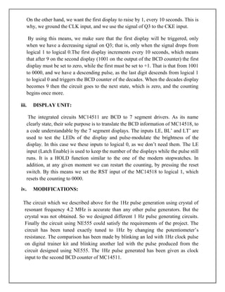
iii. Display unit
iv. Modifications*
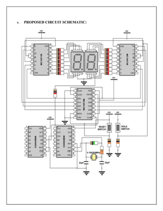
v. Schematic of proposed circuit
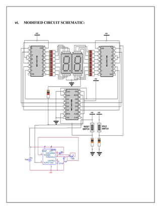
vi. Schematic of modified circuit
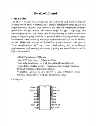
4. Details of ICs [ from Datasheets]
5. Applications of the circuit
6. Project details
i. Experiences of the project work](https://image.slidesharecdn.com/digitalstopwatch-110724001318-phpapp01/85/Digital-stop-watch-2-320.jpg)
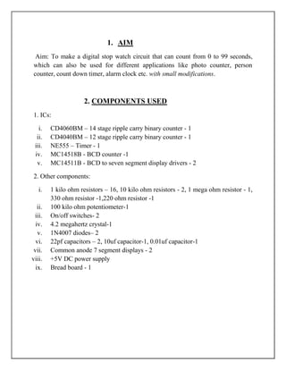
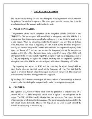

The document describes the design of a digital stopwatch circuit using integrated circuits. The circuit uses a pulse generator to create a 1Hz clock signal, a counter integrated circuit to count the pulses and track seconds and decades, and display driver integrated circuits to show the time on 7-segment displays. With minor modifications, the circuit could be adapted for applications like photo counting, people counting, timers, and alarms. Building the circuit provided learning experiences in pulse generation, troubleshooting circuits, using displays and drivers, and soldering circuits on PCBs.