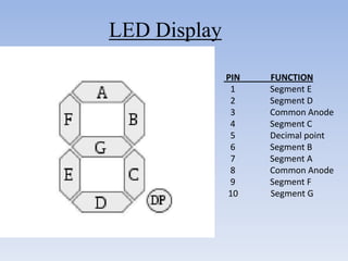
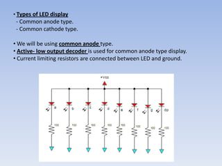
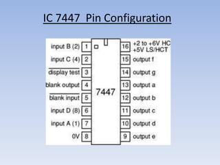
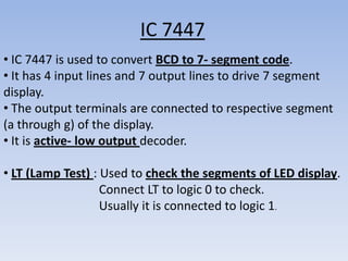
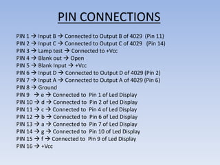
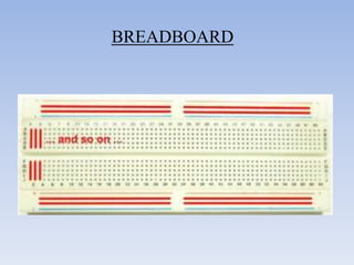
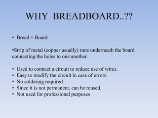
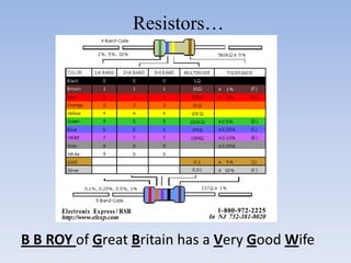
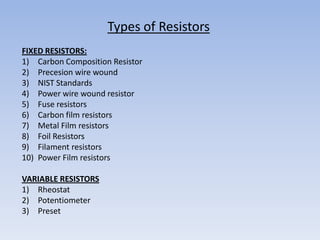
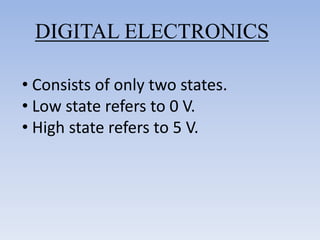
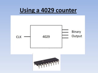
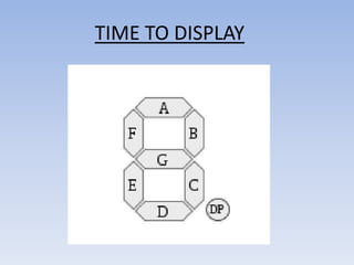
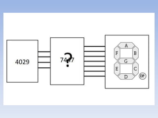
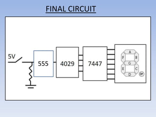
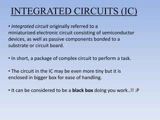
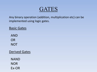
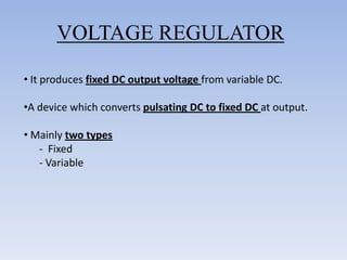
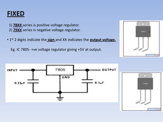
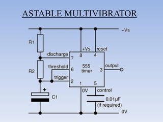
This document provides information about building a digital clock circuit. It begins by explaining components like breadboards, resistors, capacitors, logic gates and integrated circuits like the 555 timer and 4029 counter that are used. It then describes how to generate a clock pulse using a 555 timer in astable mode. A 4029 counter connected to this clock is used to count the pulses in binary coded decimal format. An 7447 decoder converts the BCD output to activate the correct segments on a 7-segment LED display to display the time digitally. Wire connections and pin configurations of the integrated circuits are provided to assemble the full circuit to build a working digital clock.


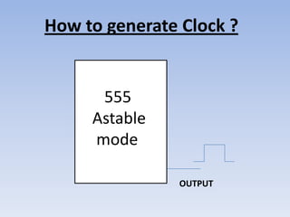
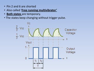
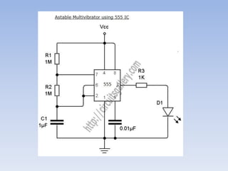
![• A duty cycle is the time that an entity spends in an active state as a fraction of the
total time under consideration.
Duty cycle = (W/T)* 100
= (R1+R2)/ (R1+2R2) *100
= 0.693 (R1+ 2R2)*C
Frequency, f= 1.44__
[(R1+2R2)*C]
T – time period
W – Width
R1, R2 – Resistances in ohms
C – Capacitance in farads
f – Frequency in hertz
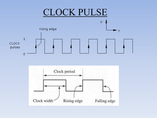
The time period can be split into two parts: T = Tm + Ts
Mark time (output high): Tm = 0.7 (R1 + R2) C1
Space time (output low): Ts = 0.7 R2 C1](https://image.slidesharecdn.com/digitalclockworkshop-120824091856-phpapp01/85/Digital-clock-workshop-39-320.jpg)