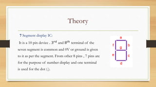
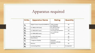
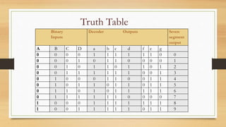
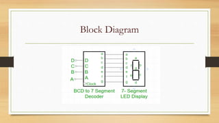
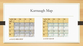
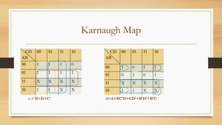
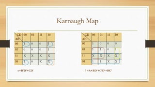
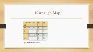
Presentation on
Digital Electronics &
Logic Design Lab
Course Code : EEE 3102
Course Title : Digital Electronics and Logic Design Lab
Presented By
Lutfun Nahar
BKH1717019F
Salma Akter
BKH1717032F
Exp. No.: 08
Exp. Name : Design and implementation of BCD to seven
segment display decoder circuit.
Overview
Objectives
Theory
Apparatus Required
Truth Table
Block Diagram
Karnaugh Map
Overview
Circuit Diagram
Experimental Setup
Logic Diagram
Discussion
Conclusion
Objectives
To familiarize with the seven segment display
To implement the circuit of BCD to seven segment display decoder
To acknowledge the applications and working capability of a seven segment
display decoder
Theory
A seven-segment display (SSD) is an electronic display device for
displaying numbers from (0 – 9). In order to produce the required number or
character, a specific combination of LED segments needs to be illuminated.
SSD takes generally a 5 V DC power supply and has 7 digital pins
named after the first 7 letters of the alphabet (a to g). The segments are lit on
by applying an ‘LOW’ logic level to the cathode. As this device is made out of
LEDs, it requires resistors in order to limit the current supply.
Theory
The BCD or Binary Coded Decimal (BCD) decoder is a device that
converts a digital format of a value into a format that displays devices such as
the 7-segment display can interpret into a human-readable For instance, we
need to use a BCD to 7-segment decoder in order to display a four-bit binary
number from 0000 (0 in base 10) to 1001 (9 in base 10 ) on a 7-segment display.
• A BCD to 7-segment display decoder is a combinational logic
circuit that takes as inputs four bits of a binary number and produces seven
digital outputs to turn on the appropriate segments of the display.
Theory
7 Segment display IC:
It is a 10 pin device . 3 𝑟𝑑 and 8 𝑡ℎ terminal of the
seven segment is common and 0V or ground is given
to it as per the segment. From other 8 pins , 7 pins are
for the purpose of number display and one terminal
is used for the dot (.).
Apparatus required
Binary
Inputs
Decoder Outputs Seven
segment
output
A B C D a b c d f e g
0 0 0 0 1 1 1 1 1 1 0 0
0 0 0 1 0 1 1 0 0 0 0 1
0 0 1 0 1 1 0 1 1 0 1 2
0 0 1 1 1 1 1 1 0 0 1 3
0 1 0 0 0 1 1 0 0 1 1 4
0 1 0 1 1 0 1 1 0 1 1 5
0 1 1 0 1 0 1 1 1 1 1 6
0 1 1 1 1 1 1 0 0 0 0 7
1 0 0 0 1 1 1 1 1 1 1 8
1 0 0 1 1 1 1 1 0 1 1 9
Truth Table
Block Diagram
Karnaugh Map
CD
AB
00 01 11 10
00 1 0 1 1
01 0 1 1 1
11 X X X X
10 1 1 X X
a=A+C+BD+B’D’
CD
AB
00 01 11 10
00 1 1 1 1
01 1 0 1 0
11 X X X X
10 1 1 X X
b=C’D’+CD+B’
Karnaugh Map
CD
AB
00 01 11 10
00 1 1 1 0
01 1 1 1 1
11 X X X X
10 1 1 X X
c = B+D+C’
CD
AB
00 01 11 10
00 1 0 1 1
01 0 1 0 1
11 X X X X
10 1 1 X X
d=A+BC’D+CD’+B’D’+B’C
Karnaugh Map
CD
AB
00 01 11 10
00 1 0 0 1
01 0 0 0 1
11 X X X X
10 1 0 X X
e=B’D’+CD’
CD
AB
00 01 11 10
00 1 0 0 0
01 1 1 0 1
11 X X X X
10 1 1 X X
f =A+BD’+C’D’+BC’
Karnaugh Map
CD
AB
00 01 11 10
00 0 0 1 1
01 1 1 0 1
11 X X X X
10 1 1 X X
g = A+CD’+BC’+B’C
Circuit Diagram
Experimental Setup
Logic Diagram
Discussion
• The specific application of using a seven-segment display as a method of
showing a numerical output for a binary counter was discussed here.
It is possible to display any single digit number on a 7 segment display by
sending a high digital signal to the specific segments that make up the number.
However this method will allow displaying only digit from 0 to 9 and letters A
to F. The only way to display number more than 9 is to use a display that has
more than 7 segments or just using multiple 7-segment displays at once
Discussion
with the corresponding BCD decoder.
In the case of the decoder circuit, any binary number between
1010 through 1111 (A to F) is an invalid input and would provide distorted
shapes on the LCD display.
Current limiting resistors of 150 ohms are connected in series
between the decoder and each of the LED display segment. They serve to limit
the maximum current flow and have no impact on the LCD display.
Conclusion
• The circuit required for this experiment is quite complex . So the
connections must be given carefully and wires must be rigid .
• The common terminal of the segment must be grounded. Before using the
logic gates, each must be checked whether it works properly or not.
• The seven segment display is highly versatile and with proper input can
display a variety of numbers , letters and figures.
Thank you

Seven segment display

  • 1.
  • 2.
    Course Code :EEE 3102 Course Title : Digital Electronics and Logic Design Lab Presented By Lutfun Nahar BKH1717019F Salma Akter BKH1717032F
  • 3.
    Exp. No.: 08 Exp.Name : Design and implementation of BCD to seven segment display decoder circuit.
  • 4.
  • 5.
  • 6.
    Objectives To familiarize withthe seven segment display To implement the circuit of BCD to seven segment display decoder To acknowledge the applications and working capability of a seven segment display decoder
  • 7.
    Theory A seven-segment display(SSD) is an electronic display device for displaying numbers from (0 – 9). In order to produce the required number or character, a specific combination of LED segments needs to be illuminated. SSD takes generally a 5 V DC power supply and has 7 digital pins named after the first 7 letters of the alphabet (a to g). The segments are lit on by applying an ‘LOW’ logic level to the cathode. As this device is made out of LEDs, it requires resistors in order to limit the current supply.
  • 8.
    Theory The BCD orBinary Coded Decimal (BCD) decoder is a device that converts a digital format of a value into a format that displays devices such as the 7-segment display can interpret into a human-readable For instance, we need to use a BCD to 7-segment decoder in order to display a four-bit binary number from 0000 (0 in base 10) to 1001 (9 in base 10 ) on a 7-segment display. • A BCD to 7-segment display decoder is a combinational logic circuit that takes as inputs four bits of a binary number and produces seven digital outputs to turn on the appropriate segments of the display.
  • 9.
    Theory 7 Segment displayIC: It is a 10 pin device . 3 𝑟𝑑 and 8 𝑡ℎ terminal of the seven segment is common and 0V or ground is given to it as per the segment. From other 8 pins , 7 pins are for the purpose of number display and one terminal is used for the dot (.).
  • 10.
  • 11.
    Binary Inputs Decoder Outputs Seven segment output AB C D a b c d f e g 0 0 0 0 1 1 1 1 1 1 0 0 0 0 0 1 0 1 1 0 0 0 0 1 0 0 1 0 1 1 0 1 1 0 1 2 0 0 1 1 1 1 1 1 0 0 1 3 0 1 0 0 0 1 1 0 0 1 1 4 0 1 0 1 1 0 1 1 0 1 1 5 0 1 1 0 1 0 1 1 1 1 1 6 0 1 1 1 1 1 1 0 0 0 0 7 1 0 0 0 1 1 1 1 1 1 1 8 1 0 0 1 1 1 1 1 0 1 1 9 Truth Table
  • 12.
  • 13.
    Karnaugh Map CD AB 00 0111 10 00 1 0 1 1 01 0 1 1 1 11 X X X X 10 1 1 X X a=A+C+BD+B’D’ CD AB 00 01 11 10 00 1 1 1 1 01 1 0 1 0 11 X X X X 10 1 1 X X b=C’D’+CD+B’
  • 14.
    Karnaugh Map CD AB 00 0111 10 00 1 1 1 0 01 1 1 1 1 11 X X X X 10 1 1 X X c = B+D+C’ CD AB 00 01 11 10 00 1 0 1 1 01 0 1 0 1 11 X X X X 10 1 1 X X d=A+BC’D+CD’+B’D’+B’C
  • 15.
    Karnaugh Map CD AB 00 0111 10 00 1 0 0 1 01 0 0 0 1 11 X X X X 10 1 0 X X e=B’D’+CD’ CD AB 00 01 11 10 00 1 0 0 0 01 1 1 0 1 11 X X X X 10 1 1 X X f =A+BD’+C’D’+BC’
  • 16.
    Karnaugh Map CD AB 00 0111 10 00 0 0 1 1 01 1 1 0 1 11 X X X X 10 1 1 X X g = A+CD’+BC’+B’C
  • 17.
  • 18.
  • 19.
  • 20.
    Discussion • The specificapplication of using a seven-segment display as a method of showing a numerical output for a binary counter was discussed here. It is possible to display any single digit number on a 7 segment display by sending a high digital signal to the specific segments that make up the number. However this method will allow displaying only digit from 0 to 9 and letters A to F. The only way to display number more than 9 is to use a display that has more than 7 segments or just using multiple 7-segment displays at once
  • 21.
    Discussion with the correspondingBCD decoder. In the case of the decoder circuit, any binary number between 1010 through 1111 (A to F) is an invalid input and would provide distorted shapes on the LCD display. Current limiting resistors of 150 ohms are connected in series between the decoder and each of the LED display segment. They serve to limit the maximum current flow and have no impact on the LCD display.
  • 22.
    Conclusion • The circuitrequired for this experiment is quite complex . So the connections must be given carefully and wires must be rigid . • The common terminal of the segment must be grounded. Before using the logic gates, each must be checked whether it works properly or not. • The seven segment display is highly versatile and with proper input can display a variety of numbers , letters and figures.
  • 23.