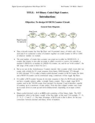
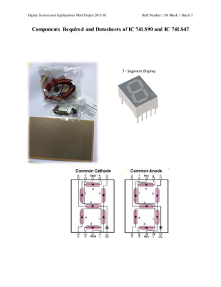
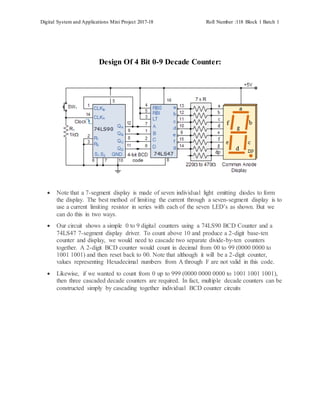
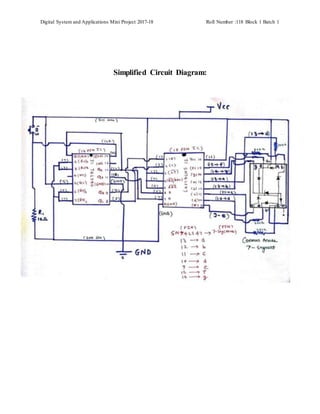
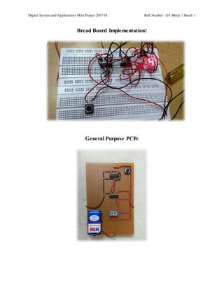
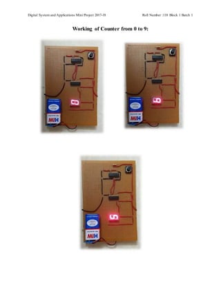
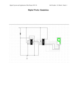
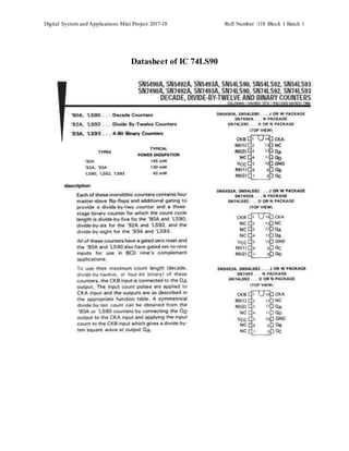
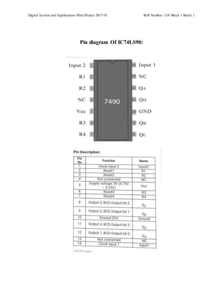
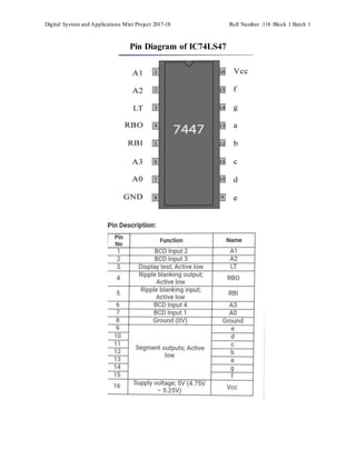
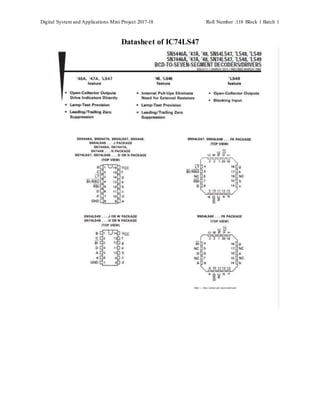
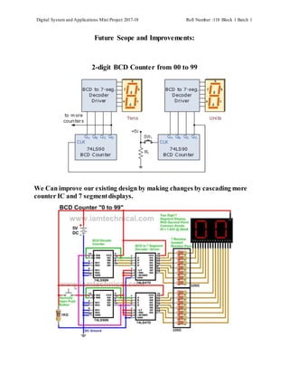
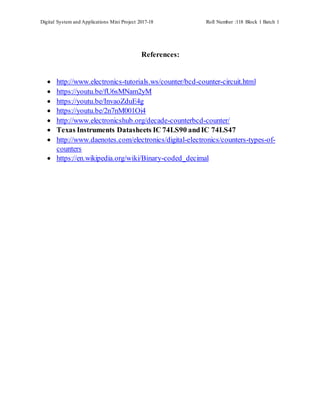
SlideShare a Scribd company logo
Digital System and Applications Mini Project 2017-18 Roll Number :118 Block 1 Batch 1
Index
1. INTRODUCTION.
1.1 Objective of Project
2. LITERATURE SURVEY:
1.1 Existing System
3. DESIGN.
3.1 Module design and organization
3.2 Components and Requirements.
3.3 Explanation of Working System
3. IMPLEMENTATION & RESULTS.
4. Future scopes
5. Datasheets
6. CONCLUSION OF PROJECT.
7. References
Digital System and Applications Mini Project 2017-18 Roll Number :118 Block 1 Batch 1
TITLE: 0-9 Binary Coded Digit Counter.
Introduction:
Objective: To design 0-9 BCD Counter Circuit
General State Diagram:
 Then a decade counter has four flip-flops and 16 potential states, of which only 10 are
used and if we connected a series of counters together we could counter to 100 or 1,000
or whatever number we wanted.
 The total number of counts that a counter can count too is called its MODULUS. A
counter that returns to zero after n counts is called a modulo-n counter, for example a
modulo-8 (MOD-8), or modulo-16 (MOD-16) counter, etc, and for an “n-bit counter”, the
full range of the count is from 0 to 2n-1.
 But as we saw in the Asynchronous Counters tutorial, that a counter which resets after ten
counts with a divide-by-10 count sequence from binary 0000 (decimal “0”) through
to 1001 (decimal “9”) is called a binary-coded-decimal counter or BCD Counter for short
and a MOD-10 counter can be constructed using a minimum of four toggle flip-flops.
 It is called a BCD counter because its ten-state sequence is that of a BCD code and does
not have a regular pattern, unlike a straight binary counter. Then a single stage BCD
counter such as the 74LS90 counts from decimal 0 to decimal 9 and is therefore capable
of counting up to a maximum of nine pulses. Note also that a digital counter may count
up or count down or count up and down (bidirectional) depending on an input control
signal.
 Binary-coded-decimal code is an 8421-code consisting of four binary digits. The 8421
designation refers to the binary weight of the four digits or bits used. For example, 23
= 8,
22
= 4, 21
= 2 and 20
= 1. The main advantage of BCD code is that it allows for the easy
conversion between decimal and binary forms of numbers.
Digital System and Applications Mini Project 2017-18 Roll Number :118 Block 1 Batch 1
Existing Systems
Integrated Circuit 74LS90 BCD Counter
 The counters four outputs are designated by the letter symbol Q with a numeric subscript
equal to the binary weight of the corresponding bit in the BCD counter circuits code. So
for example, QA, QB, QC and QD. The 74LS90 counting sequence is triggered on the
negative going edge of the clock signal, that is when the clock signal CLK goes from
logic 1 (HIGH) to logic 0 (LOW).
 The additional input pins R1 and R2 are counter “reset” pins while inputs S1 and S2 are
“set” pins. When connected to logic 1, the Reset inputs R1 and R2 reset the counter back
to zero, 0 (0000), and when the Set inputs S1 and S2 are connected to logic 1, they Set
the counter to maximum, or 9 (1001) regardless of the actual count number or position.
 As we said before, the 74LS90 counter consists of a divide-by-2 counter and a divide-by-
5 counter within the same package. Then we can use either counter to produce a divide-
by-2 frequency counter only, a divide-by-5 frequency counter only or the two together to
produce our desired divide-by-10 BCD counter.
Digital System and Applications Mini Project 2017-18 Roll Number :118 Block 1 Batch 1
Integrated Circuit 74LS90 BCD Decade Counter
 Successive applications of the push-button switch, SW1 will increase the count up to
nine, 1001. At the tenth application, the outputs ABCD will reset back to zero to start a
new count sequence. With such a MOD-10 round number of pulses we can use the
decade counter to drive a digital display.
 If we want to display the count sequence using a seven-segment display, the BCD output
needs to be decoded appropriately before it can be displayed. A digital circuit that can
decode the four outputs of our 74LS90 BCD counter and light up the required segments
of the display is called a Decoder.
Digital System and Applications Mini Project 2017-18 Roll Number :118 Block 1 Batch 1
Integrated Circuit 74LS47 BCD to 7-segment Driver
 Fortunately for us, someone has already designed and developed a BCD to 7-segment
Display DecoderIC such as the 74LS47 to do just that. The 74LS47 has four inputs for
the BCD digits A, B, C and D and outputs for each of the segments of the seven-segment
display.
 Note that a standard 7-segment LED display generally has 8 input connections, one for
each LED segment and one that acts as a common terminal or connection for all the
internal display segments. Some displays also have a decimal point (DP) option.
 The 74LS47 display decoder receives the BCD code and generates the necessary signals
to activate the appropriate LED segments responsible for displaying the number of pulses
applied. As the 74LS47 decoder is designed for driving a common-anode display, a LOW
(logic-0) output will illuminate an LED segment while a HIGH (logic-1) output will turn
it “OFF”. For normal operation, the LT (Lamp test), BI/RBO (Blanking Input/Ripple
Blanking Output) and RBI (Ripple Blanking Input) must all be open or connected to
logic-1 (HIGH).
 Note that while the 74LS47 has active LOW outputs and is designed to decode a common
anode 7 segment LED display, the 74LS48 decoder/driver IC is exactly the same except
that it has active HIGH outputs designed to decode a common cathode 7 segment display.
So depending upon the type of 7-segment LED display you have you may need a 74LS47
or a 74LS48 decoder IC.
 The 74LS47 binary coded decimal inputs can be connected to the corresponding outputs
of the 74LS90 BCD Counter to display the count sequence on the 7-segment display as
shown each time the push button SW1 is pressed. By changing the position of the push
button and 10kΩ resistor, the count can be made to change on the activation or release of
the push button switch, SW1.
Digital System and Applications Mini Project 2017-18 Roll Number :118 Block 1 Batch 1
Components Required and Datasheets of IC 74LS90 and IC 74LS47
7 - Segment Display
Digital System and Applications Mini Project 2017-18 Roll Number :118 Block 1 Batch 1
Design Of 4 Bit 0-9 Decade Counter:
 Note that a 7-segment display is made of seven individual light emitting diodes to form
the display. The best method of limiting the current through a seven-segment display is to
use a current limiting resistor in series with each of the seven LED’s as shown. But we
can do this in two ways.
 Our circuit shows a simple 0 to 9 digital counters using a 74LS90 BCD Counter and a
74LS47 7-segment display driver. To count above 10 and produce a 2-digit base-ten
counter and display, we would need to cascade two separate divide-by-ten counters
together. A 2-digit BCD counter would count in decimal from 00 to 99 (0000 0000 to
1001 1001) and then reset back to 00. Note that although it will be a 2-digit counter,
values representing Hexadecimal numbers from A through F are not valid in this code.
 Likewise, if we wanted to count from 0 up to 999 (0000 0000 0000 to 1001 1001 1001),
then three cascaded decade counters are required. In fact, multiple decade counters can be
constructed simply by cascading together individual BCD counter circuits
Digital System and Applications Mini Project 2017-18 Roll Number :118 Block 1 Batch 1
Simplified Circuit Diagram:
Digital System and Applications Mini Project 2017-18 Roll Number :118 Block 1 Batch 1
Bread Board Implementation:
General Purpose PCB:
Digital System and Applications Mini Project 2017-18 Roll Number :118 Block 1 Batch 1
Working of Counter from 0 to 9:
Digital System and Applications Mini Project 2017-18 Roll Number :118 Block 1 Batch 1
Digital Works Simulation:
Digital System and Applications Mini Project 2017-18 Roll Number :118 Block 1 Batch 1
Conclusion and Summary Of 0-9 BCD Counter:
 we have seen that a BCD Counter is a device that goes through a sequence of ten states
when it is clocked and returns to 0 after the count of 9. In our simple example above, the
input clock pulses are from a push button switch but counters can be used to count many
real-world events such as counting moving objects.
 However, suitable circuitry may be required to generate the electrical pulses for each
event to be counted as these events may occur at discrete time intervals or they may be
completely random.
 In many digital electronic circuits and applications, digital counters are implemented
using Toggle flip-flops or with any other type of flip-flop that can be connected to give
the required switching function, or with the use of dedicated counting IC’s such as the
74LS90. Binary counters are counters that go through a binary sequence and an n-bit
binary counter is made of “n” number of flip-flops counting from 0 to 2n-1.
 BCD counters follow a sequence of ten states and count using BCD numbers
from 0000to 1001 and then returns to 0000 and repeats. Such a counter must have at least
four flip-flops to represent each decimal digit, since a decimal digit is represented by a
binary code with at least four bits giving a MOD-10 count.
 We have also seen that the BCD coded output can be displayed using four LED’s or with
a digital display. But to display each number from 0 to 9 requires a decoder circuit, which
translates a binary coded number representation into the appropriate logic levels on each
of the display segments.
 Display decoder circuits can be constructed from combinational logic elements and there
are many dedicated integrated circuits on the market to perform this function such as the
74LS47 BCD to 7-segment decoder/driver IC.
 Most 7-segment displays are usually used in multi-digit counting applications so by
cascading together more BCD counters, 4-digit counters giving displays with a maximum
reading of 9999 can be constructed.
 The 74LS90 BCD Counter is a very flexible counting circuit and can be used as a
frequency divider or made to divide any whole number count from 2 to 9 by feeding the
appropriate outputs back to the IC’s Reset and Set inputs.
Digital System and Applications Mini Project 2017-18 Roll Number :118 Block 1 Batch 1
Applications Of 0-9 Decade Counter:
 Bank Token Counters at cashier section.
 Couting system on automated production line.
 Digital Clocks
 Digital stop watches.
 Timers for automated water supply .
 Sensor controlled counters.
 Counting general objects in a any system.
Advantages :
 More Number of counters can be increased by increasing number of counter
IC and 7 segment displays.
 Cascading ensures that value of counter can be increased or decreased as per
applications and use.
 Counter Circuit can be used with other circuits to perform automated control
actions.
Disadvantages:
 As the number of counter size increases the complexity of building circuit
also increases.
 Costalso increases because the use of more ICs and 7 segments takes place.
Digital System and Applications Mini Project 2017-18 Roll Number :118 Block 1 Batch 1
Datasheet of IC 74LS90
Digital System and Applications Mini Project 2017-18 Roll Number :118 Block 1 Batch 1
Pin diagram Of IC74LS90:
Digital System and Applications Mini Project 2017-18 Roll Number :118 Block 1 Batch 1
Pin Diagram of IC74LS47
Digital System and Applications Mini Project 2017-18 Roll Number :118 Block 1 Batch 1
Datasheet of IC74LS47
Digital System and Applications Mini Project 2017-18 Roll Number :118 Block 1 Batch 1
Future Scope and Improvements:
2-digit BCD Counter from 00 to 99
We Can improve our existing design by making changes by cascading more
counter IC and 7 segmentdisplays.
Digital System and Applications Mini Project 2017-18 Roll Number :118 Block 1 Batch 1
References:
 http://www.electronics-tutorials.ws/counter/bcd-counter-circuit.html
 https://youtu.be/fU6sMNam2yM
 https://youtu.be/InvaoZduE4g
 https://youtu.be/2n7nM001Oi4
 http://www.electronicshub.org/decade-counterbcd-counter/
 Texas Instruments Datasheets IC 74LS90 andIC 74LS47
 http://www.daenotes.com/electronics/digital-electronics/counters-types-of-
counters
 https://en.wikipedia.org/wiki/Binary-coded_decimal

More Related Content

What's hot

Shift Registers
Shift RegistersShift Registers
Shift Registers
Abhilash Nair
 
555 Timer (detailed presentation)
555 Timer (detailed presentation)555 Timer (detailed presentation)
555 Timer (detailed presentation)
Tanish Gupta
 
Synchronous Counter
Synchronous Counter Synchronous Counter
Synchronous Counter
Akhilesh Kushwaha
 
Encoder & Decoder
Encoder & DecoderEncoder & Decoder
Encoder & Decoder
Syed Saeed
 
Counters
CountersCounters
Counters
Randaqra
 
Counter
CounterCounter
Counter
Naufal Qodari
 
Latches and flip flop
Latches and flip flopLatches and flip flop
Latches and flip flop
Shuaib Hotak
 
Silicon control rectifier
Silicon control rectifierSilicon control rectifier
Silicon control rectifier
Mozammel Hoque Parvez
 
Clock Triggering
Clock TriggeringClock Triggering
Clock Triggering
AmshalEjaz1
 
Interfacing LCD with 8051 Microcontroller
Interfacing LCD with 8051 MicrocontrollerInterfacing LCD with 8051 Microcontroller
Interfacing LCD with 8051 Microcontroller
Pantech ProLabs India Pvt Ltd
 
Transistor Transistor Logic
Transistor Transistor LogicTransistor Transistor Logic
Transistor Transistor Logic
surat murthy
 
Logic Gates
Logic GatesLogic Gates
Logic Gatesstudent
 
Race around and master slave flip flop
Race around and master slave flip flopRace around and master slave flip flop
Race around and master slave flip flop
Shubham Singh
 
Sequential circuits in Digital Electronics
Sequential circuits in Digital ElectronicsSequential circuits in Digital Electronics
Sequential circuits in Digital Electronics
Vinoth Loganathan
 
Multiplexer and DeMultiplexer
Multiplexer and DeMultiplexerMultiplexer and DeMultiplexer
Multiplexer and DeMultiplexer
Estiak Khan
 
Two port network
Two port networkTwo port network
Two port network
Rajput Manthan
 
Programmable Logic Devices Plds
Programmable Logic Devices PldsProgrammable Logic Devices Plds
Programmable Logic Devices Plds
Gaditek
 
Two port network
Two port networkTwo port network
Two port network
Pinky Chaudhari
 
Bcd
BcdBcd
Digital Clock
Digital ClockDigital Clock
Digital Clock
JiaahRajpout123
 

What's hot (20)

Shift Registers
Shift RegistersShift Registers
Shift Registers
 
555 Timer (detailed presentation)
555 Timer (detailed presentation)555 Timer (detailed presentation)
555 Timer (detailed presentation)
 
Synchronous Counter
Synchronous Counter Synchronous Counter
Synchronous Counter
 
Encoder & Decoder
Encoder & DecoderEncoder & Decoder
Encoder & Decoder
 
Counters
CountersCounters
Counters
 
Counter
CounterCounter
Counter
 
Latches and flip flop
Latches and flip flopLatches and flip flop
Latches and flip flop
 
Silicon control rectifier
Silicon control rectifierSilicon control rectifier
Silicon control rectifier
 
Clock Triggering
Clock TriggeringClock Triggering
Clock Triggering
 
Interfacing LCD with 8051 Microcontroller
Interfacing LCD with 8051 MicrocontrollerInterfacing LCD with 8051 Microcontroller
Interfacing LCD with 8051 Microcontroller
 
Transistor Transistor Logic
Transistor Transistor LogicTransistor Transistor Logic
Transistor Transistor Logic
 
Logic Gates
Logic GatesLogic Gates
Logic Gates
 
Race around and master slave flip flop
Race around and master slave flip flopRace around and master slave flip flop
Race around and master slave flip flop
 
Sequential circuits in Digital Electronics
Sequential circuits in Digital ElectronicsSequential circuits in Digital Electronics
Sequential circuits in Digital Electronics
 
Multiplexer and DeMultiplexer
Multiplexer and DeMultiplexerMultiplexer and DeMultiplexer
Multiplexer and DeMultiplexer
 
Two port network
Two port networkTwo port network
Two port network
 
Programmable Logic Devices Plds
Programmable Logic Devices PldsProgrammable Logic Devices Plds
Programmable Logic Devices Plds
 
Two port network
Two port networkTwo port network
Two port network
 
Bcd
BcdBcd
Bcd
 
Digital Clock
Digital ClockDigital Clock
Digital Clock
 

Similar to Project Report On 0-9 decade counter

Making Of 0-9 Decade Counter with 7 segment display
Making Of 0-9 Decade Counter with 7 segment displayMaking Of 0-9 Decade Counter with 7 segment display
Making Of 0-9 Decade Counter with 7 segment display
Omkar Rane
 
Dsa 170930180124
Dsa 170930180124Dsa 170930180124
Dsa 170930180124
Abhishek Sainkar
 
a simple bcd counter project
a simple bcd counter projecta simple bcd counter project
a simple bcd counter project
Muhammad Saif Ul Islam
 
BCD Counter
BCD CounterBCD Counter
BCD Counter
Ahmed A. Arefin
 
The decoder
The decoderThe decoder
Chapter 5: Cominational Logic with MSI and LSI
Chapter 5: Cominational Logic with MSI and LSIChapter 5: Cominational Logic with MSI and LSI
Chapter 5: Cominational Logic with MSI and LSI
Er. Nawaraj Bhandari
 
fixed-point-vs-floating-point.ppt
fixed-point-vs-floating-point.pptfixed-point-vs-floating-point.ppt
fixed-point-vs-floating-point.ppt
RavikumarR77
 
Counter digital electronics
Counter digital electronics Counter digital electronics
Counter digital electronics
Sooraj Maurya
 
Digital clock presentation
Digital clock presentationDigital clock presentation
Digital clock presentation
Aditya Jha ✅
 
Digital Clock Using Logic Gates
Digital Clock Using Logic GatesDigital Clock Using Logic Gates
Digital Clock Using Logic Gates
JalpaMaheshwari1
 
Encoder-and-decoder.pptx
Encoder-and-decoder.pptxEncoder-and-decoder.pptx
Encoder-and-decoder.pptx
KamranAli649587
 
Lecture-7(MSI Logic Ckt).ppt
Lecture-7(MSI Logic Ckt).pptLecture-7(MSI Logic Ckt).ppt
Lecture-7(MSI Logic Ckt).ppt
ShirazimMunir
 
Dee2034 chapter 6 register
Dee2034 chapter 6 registerDee2034 chapter 6 register
Dee2034 chapter 6 register
SITI SABARIAH SALIHIN
 
Training Report on embedded Systems and Robotics
Training Report on embedded  Systems and RoboticsTraining Report on embedded  Systems and Robotics
Training Report on embedded Systems and Robotics
NIT Raipur
 
An Optimal Design of UP-DOWN Counter as SAR Logic Based ADC using CMOS 45nm T...
An Optimal Design of UP-DOWN Counter as SAR Logic Based ADC using CMOS 45nm T...An Optimal Design of UP-DOWN Counter as SAR Logic Based ADC using CMOS 45nm T...
An Optimal Design of UP-DOWN Counter as SAR Logic Based ADC using CMOS 45nm T...
IJERA Editor
 

Similar to Project Report On 0-9 decade counter (20)

Making Of 0-9 Decade Counter with 7 segment display
Making Of 0-9 Decade Counter with 7 segment displayMaking Of 0-9 Decade Counter with 7 segment display
Making Of 0-9 Decade Counter with 7 segment display
 
Dsa 170930180124
Dsa 170930180124Dsa 170930180124
Dsa 170930180124
 
Bcd counter
Bcd counterBcd counter
Bcd counter
 
a simple bcd counter project
a simple bcd counter projecta simple bcd counter project
a simple bcd counter project
 
BCD Counter
BCD CounterBCD Counter
BCD Counter
 
The decoder
The decoderThe decoder
The decoder
 
Chapter 5: Cominational Logic with MSI and LSI
Chapter 5: Cominational Logic with MSI and LSIChapter 5: Cominational Logic with MSI and LSI
Chapter 5: Cominational Logic with MSI and LSI
 
Ece221 Ch7 Part1
Ece221 Ch7 Part1Ece221 Ch7 Part1
Ece221 Ch7 Part1
 
fixed-point-vs-floating-point.ppt
fixed-point-vs-floating-point.pptfixed-point-vs-floating-point.ppt
fixed-point-vs-floating-point.ppt
 
Counter digital electronics
Counter digital electronics Counter digital electronics
Counter digital electronics
 
Interfacing to
Interfacing toInterfacing to
Interfacing to
 
Digital clock presentation
Digital clock presentationDigital clock presentation
Digital clock presentation
 
Digital Clock Using Logic Gates
Digital Clock Using Logic GatesDigital Clock Using Logic Gates
Digital Clock Using Logic Gates
 
Chapter5 dek3133
Chapter5 dek3133Chapter5 dek3133
Chapter5 dek3133
 
Encoder-and-decoder.pptx
Encoder-and-decoder.pptxEncoder-and-decoder.pptx
Encoder-and-decoder.pptx
 
Lecture-7(MSI Logic Ckt).ppt
Lecture-7(MSI Logic Ckt).pptLecture-7(MSI Logic Ckt).ppt
Lecture-7(MSI Logic Ckt).ppt
 
Dee2034 chapter 6 register
Dee2034 chapter 6 registerDee2034 chapter 6 register
Dee2034 chapter 6 register
 
Training Report on embedded Systems and Robotics
Training Report on embedded  Systems and RoboticsTraining Report on embedded  Systems and Robotics
Training Report on embedded Systems and Robotics
 
8051 FINIAL
8051 FINIAL8051 FINIAL
8051 FINIAL
 
An Optimal Design of UP-DOWN Counter as SAR Logic Based ADC using CMOS 45nm T...
An Optimal Design of UP-DOWN Counter as SAR Logic Based ADC using CMOS 45nm T...An Optimal Design of UP-DOWN Counter as SAR Logic Based ADC using CMOS 45nm T...
An Optimal Design of UP-DOWN Counter as SAR Logic Based ADC using CMOS 45nm T...
 

More from Omkar Rane

Enabling SSL Elasticsearch on server
Enabling SSL Elasticsearch on serverEnabling SSL Elasticsearch on server
Enabling SSL Elasticsearch on server
Omkar Rane
 
Anti lock braking (ABS) Model based Design in MATLAB-Simulink
Anti lock braking (ABS) Model based Design in MATLAB-SimulinkAnti lock braking (ABS) Model based Design in MATLAB-Simulink
Anti lock braking (ABS) Model based Design in MATLAB-Simulink
Omkar Rane
 
Autosar fundamental
Autosar fundamentalAutosar fundamental
Autosar fundamental
Omkar Rane
 
Stress Management
Stress ManagementStress Management
Stress Management
Omkar Rane
 
Bootloaders (U-Boot)
Bootloaders (U-Boot) Bootloaders (U-Boot)
Bootloaders (U-Boot)
Omkar Rane
 
Concept of Diversity & Fading (wireless communication)
Concept of Diversity & Fading (wireless communication)Concept of Diversity & Fading (wireless communication)
Concept of Diversity & Fading (wireless communication)
Omkar Rane
 
Tata Motors GDC .LTD Internship
Tata Motors GDC .LTD Internship Tata Motors GDC .LTD Internship
Tata Motors GDC .LTD Internship
Omkar Rane
 
Machine Learning Model for M.S admissions
Machine Learning Model for M.S admissionsMachine Learning Model for M.S admissions
Machine Learning Model for M.S admissions
Omkar Rane
 
Timer 0 programming on LPC 1768
Timer 0 programming on LPC 1768Timer 0 programming on LPC 1768
Timer 0 programming on LPC 1768
Omkar Rane
 
ADC (Analog to Digital conversion) using LPC 1768
ADC (Analog to Digital conversion) using LPC 1768ADC (Analog to Digital conversion) using LPC 1768
ADC (Analog to Digital conversion) using LPC 1768
Omkar Rane
 
PWM based motor speed control using LPC 1768
PWM based motor speed control using LPC 1768PWM based motor speed control using LPC 1768
PWM based motor speed control using LPC 1768
Omkar Rane
 
UART interfacing on LPC1768 (Cortex M3 micro controller)
UART interfacing on LPC1768 (Cortex M3 micro controller)UART interfacing on LPC1768 (Cortex M3 micro controller)
UART interfacing on LPC1768 (Cortex M3 micro controller)
Omkar Rane
 
LED Blinking logic on LPC1768
LED Blinking logic on LPC1768LED Blinking logic on LPC1768
LED Blinking logic on LPC1768
Omkar Rane
 
CAN interfacing on LPC1768 (ARM Cortex M3 based Micro controller)
CAN interfacing on LPC1768 (ARM Cortex M3 based Micro controller)CAN interfacing on LPC1768 (ARM Cortex M3 based Micro controller)
CAN interfacing on LPC1768 (ARM Cortex M3 based Micro controller)
Omkar Rane
 
Vlisi Course project presentation:Keypad Scanner
Vlisi Course project presentation:Keypad ScannerVlisi Course project presentation:Keypad Scanner
Vlisi Course project presentation:Keypad Scanner
Omkar Rane
 
VlSI course project report : Keypad Scanner
VlSI course project report : Keypad Scanner VlSI course project report : Keypad Scanner
VlSI course project report : Keypad Scanner
Omkar Rane
 
LPC 1768 A study on Real Time clock features
LPC 1768 A study on Real Time clock featuresLPC 1768 A study on Real Time clock features
LPC 1768 A study on Real Time clock features
Omkar Rane
 
Nexys4ddr rm FPGA board Datasheet
Nexys4ddr rm  FPGA board DatasheetNexys4ddr rm  FPGA board Datasheet
Nexys4ddr rm FPGA board Datasheet
Omkar Rane
 
Linear Regression (Machine Learning)
Linear Regression (Machine Learning)Linear Regression (Machine Learning)
Linear Regression (Machine Learning)
Omkar Rane
 
transmission gate based design for 2:1 Multiplexer in micro-wind
transmission gate based design for 2:1 Multiplexer in micro-windtransmission gate based design for 2:1 Multiplexer in micro-wind
transmission gate based design for 2:1 Multiplexer in micro-wind
Omkar Rane
 

More from Omkar Rane (20)

Enabling SSL Elasticsearch on server
Enabling SSL Elasticsearch on serverEnabling SSL Elasticsearch on server
Enabling SSL Elasticsearch on server
 
Anti lock braking (ABS) Model based Design in MATLAB-Simulink
Anti lock braking (ABS) Model based Design in MATLAB-SimulinkAnti lock braking (ABS) Model based Design in MATLAB-Simulink
Anti lock braking (ABS) Model based Design in MATLAB-Simulink
 
Autosar fundamental
Autosar fundamentalAutosar fundamental
Autosar fundamental
 
Stress Management
Stress ManagementStress Management
Stress Management
 
Bootloaders (U-Boot)
Bootloaders (U-Boot) Bootloaders (U-Boot)
Bootloaders (U-Boot)
 
Concept of Diversity & Fading (wireless communication)
Concept of Diversity & Fading (wireless communication)Concept of Diversity & Fading (wireless communication)
Concept of Diversity & Fading (wireless communication)
 
Tata Motors GDC .LTD Internship
Tata Motors GDC .LTD Internship Tata Motors GDC .LTD Internship
Tata Motors GDC .LTD Internship
 
Machine Learning Model for M.S admissions
Machine Learning Model for M.S admissionsMachine Learning Model for M.S admissions
Machine Learning Model for M.S admissions
 
Timer 0 programming on LPC 1768
Timer 0 programming on LPC 1768Timer 0 programming on LPC 1768
Timer 0 programming on LPC 1768
 
ADC (Analog to Digital conversion) using LPC 1768
ADC (Analog to Digital conversion) using LPC 1768ADC (Analog to Digital conversion) using LPC 1768
ADC (Analog to Digital conversion) using LPC 1768
 
PWM based motor speed control using LPC 1768
PWM based motor speed control using LPC 1768PWM based motor speed control using LPC 1768
PWM based motor speed control using LPC 1768
 
UART interfacing on LPC1768 (Cortex M3 micro controller)
UART interfacing on LPC1768 (Cortex M3 micro controller)UART interfacing on LPC1768 (Cortex M3 micro controller)
UART interfacing on LPC1768 (Cortex M3 micro controller)
 
LED Blinking logic on LPC1768
LED Blinking logic on LPC1768LED Blinking logic on LPC1768
LED Blinking logic on LPC1768
 
CAN interfacing on LPC1768 (ARM Cortex M3 based Micro controller)
CAN interfacing on LPC1768 (ARM Cortex M3 based Micro controller)CAN interfacing on LPC1768 (ARM Cortex M3 based Micro controller)
CAN interfacing on LPC1768 (ARM Cortex M3 based Micro controller)
 
Vlisi Course project presentation:Keypad Scanner
Vlisi Course project presentation:Keypad ScannerVlisi Course project presentation:Keypad Scanner
Vlisi Course project presentation:Keypad Scanner
 
VlSI course project report : Keypad Scanner
VlSI course project report : Keypad Scanner VlSI course project report : Keypad Scanner
VlSI course project report : Keypad Scanner
 
LPC 1768 A study on Real Time clock features
LPC 1768 A study on Real Time clock featuresLPC 1768 A study on Real Time clock features
LPC 1768 A study on Real Time clock features
 
Nexys4ddr rm FPGA board Datasheet
Nexys4ddr rm  FPGA board DatasheetNexys4ddr rm  FPGA board Datasheet
Nexys4ddr rm FPGA board Datasheet
 
Linear Regression (Machine Learning)
Linear Regression (Machine Learning)Linear Regression (Machine Learning)
Linear Regression (Machine Learning)
 
transmission gate based design for 2:1 Multiplexer in micro-wind
transmission gate based design for 2:1 Multiplexer in micro-windtransmission gate based design for 2:1 Multiplexer in micro-wind
transmission gate based design for 2:1 Multiplexer in micro-wind
 

Recently uploaded

Fundamentals of Electric Drives and its applications.pptx
Fundamentals of Electric Drives and its applications.pptxFundamentals of Electric Drives and its applications.pptx
Fundamentals of Electric Drives and its applications.pptx
manasideore6
 
Final project report on grocery store management system..pdf
Final project report on grocery store management system..pdfFinal project report on grocery store management system..pdf
Final project report on grocery store management system..pdf
Kamal Acharya
 
An Approach to Detecting Writing Styles Based on Clustering Techniques
An Approach to Detecting Writing Styles Based on Clustering TechniquesAn Approach to Detecting Writing Styles Based on Clustering Techniques
An Approach to Detecting Writing Styles Based on Clustering Techniques
ambekarshweta25
 
KuberTENes Birthday Bash Guadalajara - K8sGPT first impressions
KuberTENes Birthday Bash Guadalajara - K8sGPT first impressionsKuberTENes Birthday Bash Guadalajara - K8sGPT first impressions
KuberTENes Birthday Bash Guadalajara - K8sGPT first impressions
Victor Morales
 
PPT on GRP pipes manufacturing and testing
PPT on GRP pipes manufacturing and testingPPT on GRP pipes manufacturing and testing
PPT on GRP pipes manufacturing and testing
anoopmanoharan2
 
6th International Conference on Machine Learning & Applications (CMLA 2024)
6th International Conference on Machine Learning & Applications (CMLA 2024)6th International Conference on Machine Learning & Applications (CMLA 2024)
6th International Conference on Machine Learning & Applications (CMLA 2024)
ClaraZara1
 
Top 10 Oil and Gas Projects in Saudi Arabia 2024.pdf
Top 10 Oil and Gas Projects in Saudi Arabia 2024.pdfTop 10 Oil and Gas Projects in Saudi Arabia 2024.pdf
Top 10 Oil and Gas Projects in Saudi Arabia 2024.pdf
Teleport Manpower Consultant
 
Literature Review Basics and Understanding Reference Management.pptx
Literature Review Basics and Understanding Reference Management.pptxLiterature Review Basics and Understanding Reference Management.pptx
Literature Review Basics and Understanding Reference Management.pptx
Dr Ramhari Poudyal
 
Fundamentals of Induction Motor Drives.pptx
Fundamentals of Induction Motor Drives.pptxFundamentals of Induction Motor Drives.pptx
Fundamentals of Induction Motor Drives.pptx
manasideore6
 
RAT: Retrieval Augmented Thoughts Elicit Context-Aware Reasoning in Long-Hori...
RAT: Retrieval Augmented Thoughts Elicit Context-Aware Reasoning in Long-Hori...RAT: Retrieval Augmented Thoughts Elicit Context-Aware Reasoning in Long-Hori...
RAT: Retrieval Augmented Thoughts Elicit Context-Aware Reasoning in Long-Hori...
thanhdowork
 
一比一原版(UofT毕业证)多伦多大学毕业证成绩单如何办理
一比一原版(UofT毕业证)多伦多大学毕业证成绩单如何办理一比一原版(UofT毕业证)多伦多大学毕业证成绩单如何办理
一比一原版(UofT毕业证)多伦多大学毕业证成绩单如何办理
ydteq
 
一比一原版(Otago毕业证)奥塔哥大学毕业证成绩单如何办理
一比一原版(Otago毕业证)奥塔哥大学毕业证成绩单如何办理一比一原版(Otago毕业证)奥塔哥大学毕业证成绩单如何办理
一比一原版(Otago毕业证)奥塔哥大学毕业证成绩单如何办理
dxobcob
 
Technical Drawings introduction to drawing of prisms
Technical Drawings introduction to drawing of prismsTechnical Drawings introduction to drawing of prisms
Technical Drawings introduction to drawing of prisms
heavyhaig
 
DfMAy 2024 - key insights and contributions
DfMAy 2024 - key insights and contributionsDfMAy 2024 - key insights and contributions
DfMAy 2024 - key insights and contributions
gestioneergodomus
 
Nuclear Power Economics and Structuring 2024
Nuclear Power Economics and Structuring 2024Nuclear Power Economics and Structuring 2024
Nuclear Power Economics and Structuring 2024
Massimo Talia
 
Online aptitude test management system project report.pdf
Online aptitude test management system project report.pdfOnline aptitude test management system project report.pdf
Online aptitude test management system project report.pdf
Kamal Acharya
 
Pile Foundation by Venkatesh Taduvai (Sub Geotechnical Engineering II)-conver...
Pile Foundation by Venkatesh Taduvai (Sub Geotechnical Engineering II)-conver...Pile Foundation by Venkatesh Taduvai (Sub Geotechnical Engineering II)-conver...
Pile Foundation by Venkatesh Taduvai (Sub Geotechnical Engineering II)-conver...
AJAYKUMARPUND1
 
Student information management system project report ii.pdf
Student information management system project report ii.pdfStudent information management system project report ii.pdf
Student information management system project report ii.pdf
Kamal Acharya
 
digital fundamental by Thomas L.floydl.pdf
digital fundamental by Thomas L.floydl.pdfdigital fundamental by Thomas L.floydl.pdf
digital fundamental by Thomas L.floydl.pdf
drwaing
 
Modelagem de um CSTR com reação endotermica.pdf
Modelagem de um CSTR com reação endotermica.pdfModelagem de um CSTR com reação endotermica.pdf
Modelagem de um CSTR com reação endotermica.pdf
camseq
 

Recently uploaded (20)

Fundamentals of Electric Drives and its applications.pptx
Fundamentals of Electric Drives and its applications.pptxFundamentals of Electric Drives and its applications.pptx
Fundamentals of Electric Drives and its applications.pptx
 
Final project report on grocery store management system..pdf
Final project report on grocery store management system..pdfFinal project report on grocery store management system..pdf
Final project report on grocery store management system..pdf
 
An Approach to Detecting Writing Styles Based on Clustering Techniques
An Approach to Detecting Writing Styles Based on Clustering TechniquesAn Approach to Detecting Writing Styles Based on Clustering Techniques
An Approach to Detecting Writing Styles Based on Clustering Techniques
 
KuberTENes Birthday Bash Guadalajara - K8sGPT first impressions
KuberTENes Birthday Bash Guadalajara - K8sGPT first impressionsKuberTENes Birthday Bash Guadalajara - K8sGPT first impressions
KuberTENes Birthday Bash Guadalajara - K8sGPT first impressions
 
PPT on GRP pipes manufacturing and testing
PPT on GRP pipes manufacturing and testingPPT on GRP pipes manufacturing and testing
PPT on GRP pipes manufacturing and testing
 
6th International Conference on Machine Learning & Applications (CMLA 2024)
6th International Conference on Machine Learning & Applications (CMLA 2024)6th International Conference on Machine Learning & Applications (CMLA 2024)
6th International Conference on Machine Learning & Applications (CMLA 2024)
 
Top 10 Oil and Gas Projects in Saudi Arabia 2024.pdf
Top 10 Oil and Gas Projects in Saudi Arabia 2024.pdfTop 10 Oil and Gas Projects in Saudi Arabia 2024.pdf
Top 10 Oil and Gas Projects in Saudi Arabia 2024.pdf
 
Literature Review Basics and Understanding Reference Management.pptx
Literature Review Basics and Understanding Reference Management.pptxLiterature Review Basics and Understanding Reference Management.pptx
Literature Review Basics and Understanding Reference Management.pptx
 
Fundamentals of Induction Motor Drives.pptx
Fundamentals of Induction Motor Drives.pptxFundamentals of Induction Motor Drives.pptx
Fundamentals of Induction Motor Drives.pptx
 
RAT: Retrieval Augmented Thoughts Elicit Context-Aware Reasoning in Long-Hori...
RAT: Retrieval Augmented Thoughts Elicit Context-Aware Reasoning in Long-Hori...RAT: Retrieval Augmented Thoughts Elicit Context-Aware Reasoning in Long-Hori...
RAT: Retrieval Augmented Thoughts Elicit Context-Aware Reasoning in Long-Hori...
 
一比一原版(UofT毕业证)多伦多大学毕业证成绩单如何办理
一比一原版(UofT毕业证)多伦多大学毕业证成绩单如何办理一比一原版(UofT毕业证)多伦多大学毕业证成绩单如何办理
一比一原版(UofT毕业证)多伦多大学毕业证成绩单如何办理
 
一比一原版(Otago毕业证)奥塔哥大学毕业证成绩单如何办理
一比一原版(Otago毕业证)奥塔哥大学毕业证成绩单如何办理一比一原版(Otago毕业证)奥塔哥大学毕业证成绩单如何办理
一比一原版(Otago毕业证)奥塔哥大学毕业证成绩单如何办理
 
Technical Drawings introduction to drawing of prisms
Technical Drawings introduction to drawing of prismsTechnical Drawings introduction to drawing of prisms
Technical Drawings introduction to drawing of prisms
 
DfMAy 2024 - key insights and contributions
DfMAy 2024 - key insights and contributionsDfMAy 2024 - key insights and contributions
DfMAy 2024 - key insights and contributions
 
Nuclear Power Economics and Structuring 2024
Nuclear Power Economics and Structuring 2024Nuclear Power Economics and Structuring 2024
Nuclear Power Economics and Structuring 2024
 
Online aptitude test management system project report.pdf
Online aptitude test management system project report.pdfOnline aptitude test management system project report.pdf
Online aptitude test management system project report.pdf
 
Pile Foundation by Venkatesh Taduvai (Sub Geotechnical Engineering II)-conver...
Pile Foundation by Venkatesh Taduvai (Sub Geotechnical Engineering II)-conver...Pile Foundation by Venkatesh Taduvai (Sub Geotechnical Engineering II)-conver...
Pile Foundation by Venkatesh Taduvai (Sub Geotechnical Engineering II)-conver...
 
Student information management system project report ii.pdf
Student information management system project report ii.pdfStudent information management system project report ii.pdf
Student information management system project report ii.pdf
 
digital fundamental by Thomas L.floydl.pdf
digital fundamental by Thomas L.floydl.pdfdigital fundamental by Thomas L.floydl.pdf
digital fundamental by Thomas L.floydl.pdf
 
Modelagem de um CSTR com reação endotermica.pdf
Modelagem de um CSTR com reação endotermica.pdfModelagem de um CSTR com reação endotermica.pdf
Modelagem de um CSTR com reação endotermica.pdf
 

Project Report On 0-9 decade counter

  • 1. Digital System and Applications Mini Project 2017-18 Roll Number :118 Block 1 Batch 1 Index 1. INTRODUCTION. 1.1 Objective of Project 2. LITERATURE SURVEY: 1.1 Existing System 3. DESIGN. 3.1 Module design and organization 3.2 Components and Requirements. 3.3 Explanation of Working System 3. IMPLEMENTATION & RESULTS. 4. Future scopes 5. Datasheets 6. CONCLUSION OF PROJECT. 7. References
  • 2. Digital System and Applications Mini Project 2017-18 Roll Number :118 Block 1 Batch 1 TITLE: 0-9 Binary Coded Digit Counter. Introduction: Objective: To design 0-9 BCD Counter Circuit General State Diagram:  Then a decade counter has four flip-flops and 16 potential states, of which only 10 are used and if we connected a series of counters together we could counter to 100 or 1,000 or whatever number we wanted.  The total number of counts that a counter can count too is called its MODULUS. A counter that returns to zero after n counts is called a modulo-n counter, for example a modulo-8 (MOD-8), or modulo-16 (MOD-16) counter, etc, and for an “n-bit counter”, the full range of the count is from 0 to 2n-1.  But as we saw in the Asynchronous Counters tutorial, that a counter which resets after ten counts with a divide-by-10 count sequence from binary 0000 (decimal “0”) through to 1001 (decimal “9”) is called a binary-coded-decimal counter or BCD Counter for short and a MOD-10 counter can be constructed using a minimum of four toggle flip-flops.  It is called a BCD counter because its ten-state sequence is that of a BCD code and does not have a regular pattern, unlike a straight binary counter. Then a single stage BCD counter such as the 74LS90 counts from decimal 0 to decimal 9 and is therefore capable of counting up to a maximum of nine pulses. Note also that a digital counter may count up or count down or count up and down (bidirectional) depending on an input control signal.  Binary-coded-decimal code is an 8421-code consisting of four binary digits. The 8421 designation refers to the binary weight of the four digits or bits used. For example, 23 = 8, 22 = 4, 21 = 2 and 20 = 1. The main advantage of BCD code is that it allows for the easy conversion between decimal and binary forms of numbers.
  • 3. Digital System and Applications Mini Project 2017-18 Roll Number :118 Block 1 Batch 1 Existing Systems Integrated Circuit 74LS90 BCD Counter  The counters four outputs are designated by the letter symbol Q with a numeric subscript equal to the binary weight of the corresponding bit in the BCD counter circuits code. So for example, QA, QB, QC and QD. The 74LS90 counting sequence is triggered on the negative going edge of the clock signal, that is when the clock signal CLK goes from logic 1 (HIGH) to logic 0 (LOW).  The additional input pins R1 and R2 are counter “reset” pins while inputs S1 and S2 are “set” pins. When connected to logic 1, the Reset inputs R1 and R2 reset the counter back to zero, 0 (0000), and when the Set inputs S1 and S2 are connected to logic 1, they Set the counter to maximum, or 9 (1001) regardless of the actual count number or position.  As we said before, the 74LS90 counter consists of a divide-by-2 counter and a divide-by- 5 counter within the same package. Then we can use either counter to produce a divide- by-2 frequency counter only, a divide-by-5 frequency counter only or the two together to produce our desired divide-by-10 BCD counter.
  • 4. Digital System and Applications Mini Project 2017-18 Roll Number :118 Block 1 Batch 1 Integrated Circuit 74LS90 BCD Decade Counter  Successive applications of the push-button switch, SW1 will increase the count up to nine, 1001. At the tenth application, the outputs ABCD will reset back to zero to start a new count sequence. With such a MOD-10 round number of pulses we can use the decade counter to drive a digital display.  If we want to display the count sequence using a seven-segment display, the BCD output needs to be decoded appropriately before it can be displayed. A digital circuit that can decode the four outputs of our 74LS90 BCD counter and light up the required segments of the display is called a Decoder.
  • 5. Digital System and Applications Mini Project 2017-18 Roll Number :118 Block 1 Batch 1 Integrated Circuit 74LS47 BCD to 7-segment Driver  Fortunately for us, someone has already designed and developed a BCD to 7-segment Display DecoderIC such as the 74LS47 to do just that. The 74LS47 has four inputs for the BCD digits A, B, C and D and outputs for each of the segments of the seven-segment display.  Note that a standard 7-segment LED display generally has 8 input connections, one for each LED segment and one that acts as a common terminal or connection for all the internal display segments. Some displays also have a decimal point (DP) option.  The 74LS47 display decoder receives the BCD code and generates the necessary signals to activate the appropriate LED segments responsible for displaying the number of pulses applied. As the 74LS47 decoder is designed for driving a common-anode display, a LOW (logic-0) output will illuminate an LED segment while a HIGH (logic-1) output will turn it “OFF”. For normal operation, the LT (Lamp test), BI/RBO (Blanking Input/Ripple Blanking Output) and RBI (Ripple Blanking Input) must all be open or connected to logic-1 (HIGH).  Note that while the 74LS47 has active LOW outputs and is designed to decode a common anode 7 segment LED display, the 74LS48 decoder/driver IC is exactly the same except that it has active HIGH outputs designed to decode a common cathode 7 segment display. So depending upon the type of 7-segment LED display you have you may need a 74LS47 or a 74LS48 decoder IC.  The 74LS47 binary coded decimal inputs can be connected to the corresponding outputs of the 74LS90 BCD Counter to display the count sequence on the 7-segment display as shown each time the push button SW1 is pressed. By changing the position of the push button and 10kΩ resistor, the count can be made to change on the activation or release of the push button switch, SW1.
  • 6. Digital System and Applications Mini Project 2017-18 Roll Number :118 Block 1 Batch 1 Components Required and Datasheets of IC 74LS90 and IC 74LS47 7 - Segment Display
  • 7. Digital System and Applications Mini Project 2017-18 Roll Number :118 Block 1 Batch 1 Design Of 4 Bit 0-9 Decade Counter:  Note that a 7-segment display is made of seven individual light emitting diodes to form the display. The best method of limiting the current through a seven-segment display is to use a current limiting resistor in series with each of the seven LED’s as shown. But we can do this in two ways.  Our circuit shows a simple 0 to 9 digital counters using a 74LS90 BCD Counter and a 74LS47 7-segment display driver. To count above 10 and produce a 2-digit base-ten counter and display, we would need to cascade two separate divide-by-ten counters together. A 2-digit BCD counter would count in decimal from 00 to 99 (0000 0000 to 1001 1001) and then reset back to 00. Note that although it will be a 2-digit counter, values representing Hexadecimal numbers from A through F are not valid in this code.  Likewise, if we wanted to count from 0 up to 999 (0000 0000 0000 to 1001 1001 1001), then three cascaded decade counters are required. In fact, multiple decade counters can be constructed simply by cascading together individual BCD counter circuits
  • 8. Digital System and Applications Mini Project 2017-18 Roll Number :118 Block 1 Batch 1 Simplified Circuit Diagram:
  • 9. Digital System and Applications Mini Project 2017-18 Roll Number :118 Block 1 Batch 1 Bread Board Implementation: General Purpose PCB:
  • 10. Digital System and Applications Mini Project 2017-18 Roll Number :118 Block 1 Batch 1 Working of Counter from 0 to 9:
  • 11. Digital System and Applications Mini Project 2017-18 Roll Number :118 Block 1 Batch 1 Digital Works Simulation:
  • 12. Digital System and Applications Mini Project 2017-18 Roll Number :118 Block 1 Batch 1 Conclusion and Summary Of 0-9 BCD Counter:  we have seen that a BCD Counter is a device that goes through a sequence of ten states when it is clocked and returns to 0 after the count of 9. In our simple example above, the input clock pulses are from a push button switch but counters can be used to count many real-world events such as counting moving objects.  However, suitable circuitry may be required to generate the electrical pulses for each event to be counted as these events may occur at discrete time intervals or they may be completely random.  In many digital electronic circuits and applications, digital counters are implemented using Toggle flip-flops or with any other type of flip-flop that can be connected to give the required switching function, or with the use of dedicated counting IC’s such as the 74LS90. Binary counters are counters that go through a binary sequence and an n-bit binary counter is made of “n” number of flip-flops counting from 0 to 2n-1.  BCD counters follow a sequence of ten states and count using BCD numbers from 0000to 1001 and then returns to 0000 and repeats. Such a counter must have at least four flip-flops to represent each decimal digit, since a decimal digit is represented by a binary code with at least four bits giving a MOD-10 count.  We have also seen that the BCD coded output can be displayed using four LED’s or with a digital display. But to display each number from 0 to 9 requires a decoder circuit, which translates a binary coded number representation into the appropriate logic levels on each of the display segments.  Display decoder circuits can be constructed from combinational logic elements and there are many dedicated integrated circuits on the market to perform this function such as the 74LS47 BCD to 7-segment decoder/driver IC.  Most 7-segment displays are usually used in multi-digit counting applications so by cascading together more BCD counters, 4-digit counters giving displays with a maximum reading of 9999 can be constructed.  The 74LS90 BCD Counter is a very flexible counting circuit and can be used as a frequency divider or made to divide any whole number count from 2 to 9 by feeding the appropriate outputs back to the IC’s Reset and Set inputs.
  • 13. Digital System and Applications Mini Project 2017-18 Roll Number :118 Block 1 Batch 1 Applications Of 0-9 Decade Counter:  Bank Token Counters at cashier section.  Couting system on automated production line.  Digital Clocks  Digital stop watches.  Timers for automated water supply .  Sensor controlled counters.  Counting general objects in a any system. Advantages :  More Number of counters can be increased by increasing number of counter IC and 7 segment displays.  Cascading ensures that value of counter can be increased or decreased as per applications and use.  Counter Circuit can be used with other circuits to perform automated control actions. Disadvantages:  As the number of counter size increases the complexity of building circuit also increases.  Costalso increases because the use of more ICs and 7 segments takes place.
  • 14. Digital System and Applications Mini Project 2017-18 Roll Number :118 Block 1 Batch 1 Datasheet of IC 74LS90
  • 15. Digital System and Applications Mini Project 2017-18 Roll Number :118 Block 1 Batch 1 Pin diagram Of IC74LS90:
  • 16. Digital System and Applications Mini Project 2017-18 Roll Number :118 Block 1 Batch 1 Pin Diagram of IC74LS47
  • 17. Digital System and Applications Mini Project 2017-18 Roll Number :118 Block 1 Batch 1 Datasheet of IC74LS47
  • 18. Digital System and Applications Mini Project 2017-18 Roll Number :118 Block 1 Batch 1 Future Scope and Improvements: 2-digit BCD Counter from 00 to 99 We Can improve our existing design by making changes by cascading more counter IC and 7 segmentdisplays.
  • 19. Digital System and Applications Mini Project 2017-18 Roll Number :118 Block 1 Batch 1 References:  http://www.electronics-tutorials.ws/counter/bcd-counter-circuit.html  https://youtu.be/fU6sMNam2yM  https://youtu.be/InvaoZduE4g  https://youtu.be/2n7nM001Oi4  http://www.electronicshub.org/decade-counterbcd-counter/  Texas Instruments Datasheets IC 74LS90 andIC 74LS47  http://www.daenotes.com/electronics/digital-electronics/counters-types-of- counters  https://en.wikipedia.org/wiki/Binary-coded_decimal