Downloaded 14 times

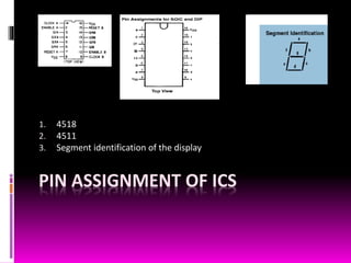
![HOW THE COUNTER WORKS
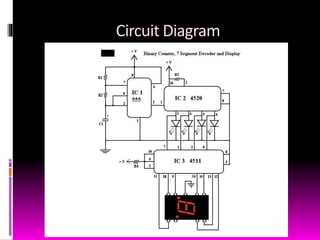
555 generates the clock pulse
4518 receives the pulse and starts counting
4511 is a decoder that collect the pulses from 4518 and sends it to the
Display.
Finally the 7 segment LED display shows the output in Decimal
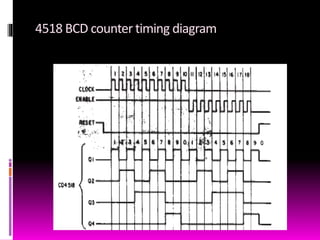
[N.B. when the decimal value reaches 9(binary 1001) in the next step it resets
the clock and goes to decimal o(binary 0000) and start counting again]](https://image.slidesharecdn.com/bcdcounterproject-170623123904/85/BCD-Counter-8-320.jpg)
![XILINX MODULE DESCRIPTION
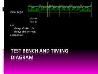
`timescale 1ns / 1ps
module bcd4bit (clk,rst,count);
input clk,rst;
output reg [0:4]count;
always @(posedge clk, negedge rst)
if (rst)
count <= 0;
else
count <= count+1;
endmodule](https://image.slidesharecdn.com/bcdcounterproject-170623123904/85/BCD-Counter-11-320.jpg)


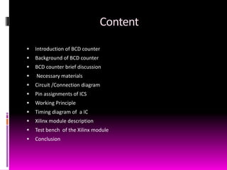
The document presents a project on building a BCD counter. It introduces the group members and provides an overview of the content which includes introduction, background, necessary materials, circuit diagram, pin assignments, working principle and timing diagram of the BCD counter. It discusses how a BCD counter works from generating a clock pulse to displaying the output in decimal on a 7 segment display. It also includes the Xilinx module description and test bench for verification.