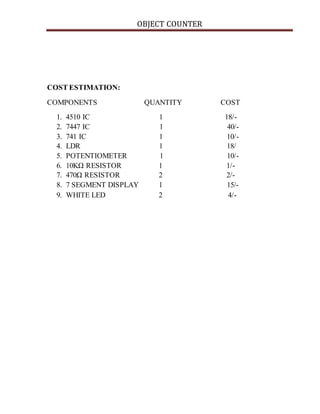
This document describes the design and working of an object counter circuit. The circuit uses an LDR sensor, op-amp, 4510 BCD counter, and 7447 seven segment decoder to count objects passing in front of the LDR. It provides the components, block diagram, circuit diagram, working principle, applications, and cost estimation of the object counter circuit. The circuit is designed to count objects in applications like manufacturing assembly lines, restaurants, banks, and airports.


![OBJECT COUNTER
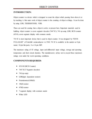
WORKING PRINCIPLE:
INPUT PART
The op-amp used in input acts as a comparator. Considering the equation V0=A[V+-V-]. Where
‘A’ is high gain factor. If we give reference voltage to inverting input terminal and input voltage
to non inverting input terminal of op-amp then output voltageV0=[Vin-vref].
The op-amp as comparator we are used to compare the input voltage to reference voltage. Op-
amp is considered as linear and it is less affected to noise. Considering the negative voltage
supply as zero potential and positive supply as one we will get the logic as follows
Vin > Vref 1
Vin < Vref 0
We are using potentiometer that is variable resistor feeding to negative terminal of op-amp.
Output from LDR is fed to positive terminal of op-amp. It is used as potential divider and its
resistance depends upon the relative rotation of variable resistor. In half rotation of potentiometer
the resistance will be R=50KΩ and reference voltage becomes
Vref =(50KΩ/100KΩ)*5=2.5V
PROCESSOR:
The main part of the processing circuit is 4510 IC. It is 16 pin DIP IC. The first pin of this IC is
preset enable, until or unless it has zero input inserted till then the whole IC will be functioning
otherwise if it is given 1 then it goes to the preset value. If we want to count the input we need to
give zero to carry input(CT).
When signal from input is given to the processor part, preset enable, clock input and reset must
be given to ground. UP/DOWN counter must be given high because we are counting numbers
from 0 to 9.
OUTPUT:
The output consists of 7 segment LED. To drive this LED we need a decoder. Since we are using
common anode 7 segment display i.e, 7447 IC. The output of 4510 IC is fed to the 7447 IC QA
is fed to A, QB is fed to B, QC is fed to C, and QD is fed to D. When LDR is disturbed by
moving object so it senses the object and count is made on 7 segment display. Hence we can
count the object passing through it.](https://image.slidesharecdn.com/objectcounter-180202070436/85/Object-counter-5-320.jpg)


![ppt on IC [Integrated Circuit]](https://cdn.slidesharecdn.com/ss_thumbnails/1-171227170055-thumbnail.jpg?width=640&height=640&fit=bounds)


![[Deck] What's New in Spark-Iceberg Integration via DSV2.pptx](https://cdn.slidesharecdn.com/ss_thumbnails/deckwhatsnewinspark-icebergintegrationviadsv2-260210005337-25955b12-thumbnail.jpg?width=640&height=640&fit=bounds)


