Downloaded 1,846 times


![Locating Pins • When reamed or finely
finished holes are available in
the workiece, these can be
used for locating purposes
(i) Conical locating pins.
These pins are used to locate a workpiece which
is cylindrical (a) and (b). Any variation in the hole
size will be easily accommodated due to the
conical shape of the pin.
(ii) Cylindrical locating pins, Fig. (c), (d) & (e)
In these pins, locating diameter of pin is made a
push fit with the hole in the workpiece, with
which it has to engage. The top portion of these
pins is given sufficient lead either by chamfering
[Fig. (c) & (d)] or by means of radius [Fig. (e)] to
facilitate the loading of the workpiece.](https://image.slidesharecdn.com/jigandfixture-160309073723/75/Jig-and-fixture-13-2048.jpg)


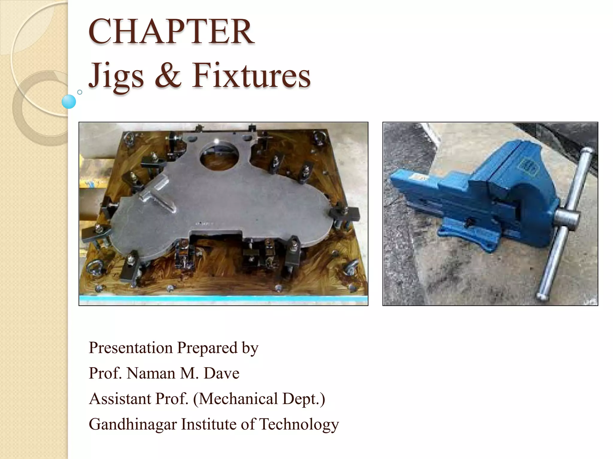
The document provides an overview of jigs and fixtures, emphasizing their role in mass production by improving efficiency, accuracy, and cost-effectiveness in machining and assembly operations. It outlines essential components, functions, and types of jigs, including drilling jigs and various designs that cater to specific machining needs. Additionally, it explains principles of locating and clamping workpieces to ensure stability and precision during processing.


