Downloaded 194 times

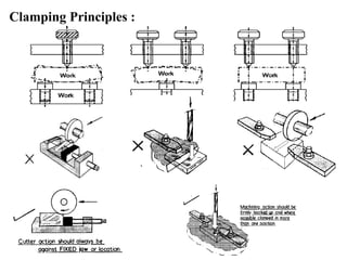
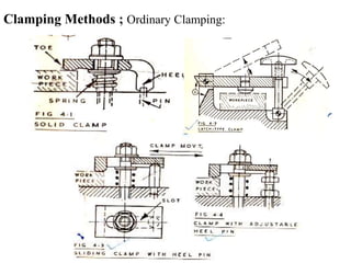
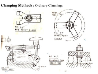
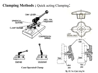
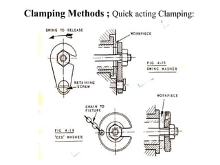
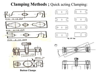
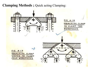
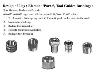
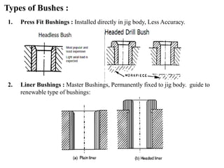
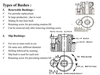
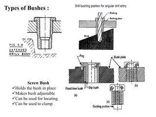
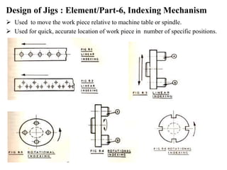
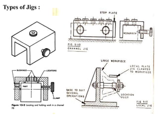
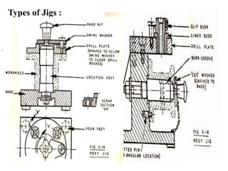
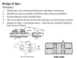
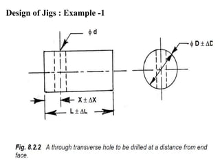
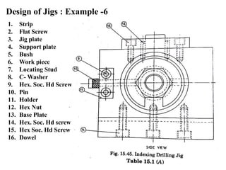
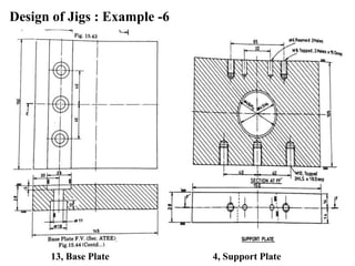
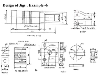


The document provides a comprehensive overview of jigs and fixtures, outlining their definitions, advantages, design principles, and various components. It details the specific elements required for effective jigs and fixtures, including locating systems, clamping methods, tool guides, and indexing mechanisms, while discussing the differences between jigs and fixtures. Additionally, the document includes design examples and references for further reading on the topic.


