Downloaded 2,488 times

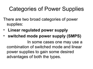
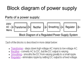
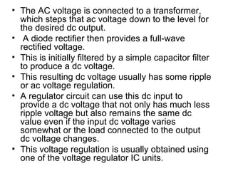
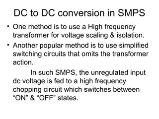
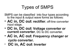
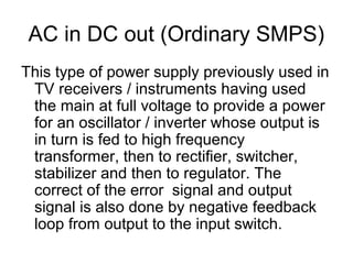
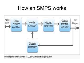
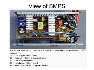
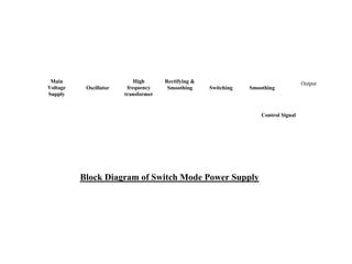
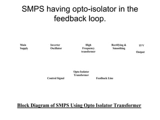
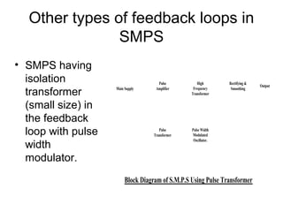
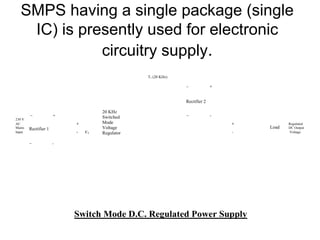


This document discusses power supplies and switched mode power supplies (SMPS). It begins with an overview of power supplies and their basic components like transformers, rectifiers, and regulators. It then covers the categories of power supplies, including linear regulated and SMPS. The document discusses the components and workings of SMPS in detail, including the inverter, output transformer, rectifier and filter. It covers the advantages of SMPS like higher efficiency and smaller size compared to traditional power supplies. In the end, it discusses different feedback techniques used in SMPS.


![REGULATED_POWER_SUPPLY-1[1].pptx](https://cdn.slidesharecdn.com/ss_thumbnails/regulatedpowersupply-11-220731133419-9084246e-thumbnail.jpg?width=640&height=640&fit=bounds)


