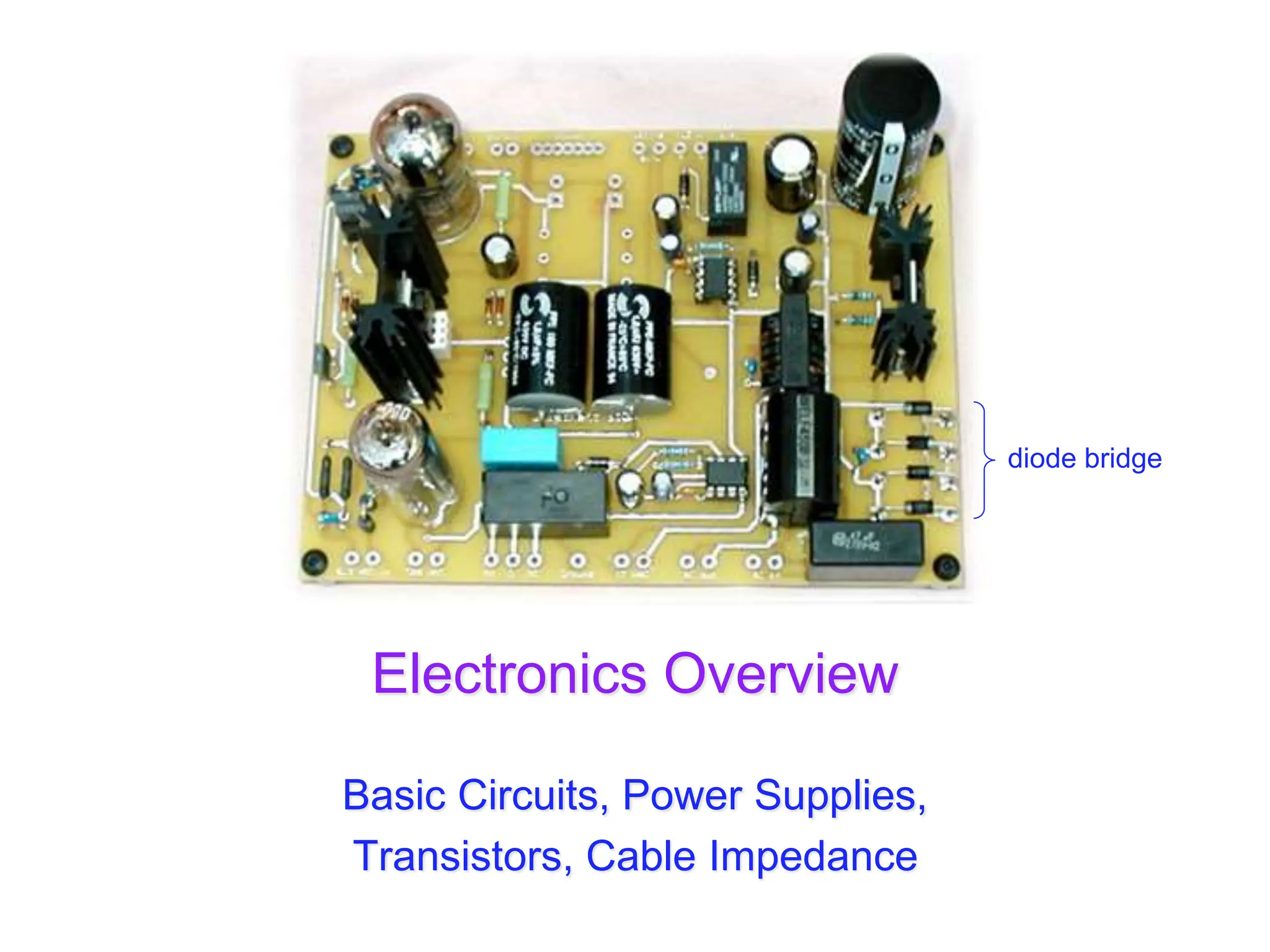
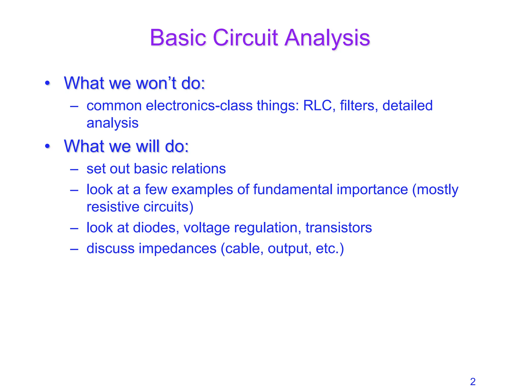
SlideShare a Scribd company logo
1 of 36
Electronics Overview
Basic Circuits, Power Supplies,
Transistors, Cable Impedance
diode bridge
2
Basic Circuit Analysis
• What we won’t do:
– common electronics-class things: RLC, filters, detailed
analysis
• What we will do:
– set out basic relations
– look at a few examples of fundamental importance (mostly
resistive circuits)
– look at diodes, voltage regulation, transistors
– discuss impedances (cable, output, etc.)
3
The Basic Relations
• V is voltage (volts: V); I is current (amps: A); R is
resistance (ohms: ); C is capacitance (farads: F); L
is inductance (henrys: H)
• Ohm’s Law: V = IR; V = ; V = L(dI/dt)
• Power: P = IV = V2/R = I2R
• Resistors and inductors in series add
• Capacitors in parallel add
• Resistors and inductors in parallel, and capacitors in
series add according to:

1
C
Idt


1
Xtot

1
X1

1
X2

1
X3

4
Example: Voltage divider
• Voltage dividers are a classic way to
set a voltage
• Works on the principle that all charge
flowing through the first resistor goes
through the second
– so V  R-value
– provided any load at output is
negligible: otherwise some current
goes there too
• So Vout = V(R2/(R1 + R2))
• R2 here is a variable resistor, or
potentiometer, or “pot”
– typically three terminals: R12 is fixed,
tap slides along to vary R13 and R23,
though R13 + R23 = R12 always
1
2
3
R1
R2
V Vout
5
Real Batteries: Output Impedance
• A power supply (battery) is characterized by a
voltage (V) and an output impedance (R)
– sometimes called source impedance
• Hooking up to load: Rload, we form a voltage
divider, so that the voltage applied by the battery
terminal is actually Vout = V(Rload/(R+Rload))
– thus the smaller R is, the “stiffer” the power supply
– when Vout sags with higher load current, we call
this “droop”
• Example: If 10.0 V power supply droops by 1%
(0.1 V) when loaded to 1 Amp (10  load):
– internal resistance is 0.1 
– called output impedance or source impedance
– may vary with load, though (not a real resistor)
V
R
D-cell example: 6A
out of 1.5 V battery
indicates 0.25  output
impedance
6
Power Supplies and Regulation
• A power supply typically starts with a transformer
– to knock down the 340 V peak-to-peak (120 V AC) to something
reasonable/manageable
• We will be using a center-tap transformer
– (A’  B’) = (winding ratio)(A  B)
• when A > B, so is A’ > B’
– geometry of center tap (CT) guarantees it is midway between A’
and B’ (frequently tie this to ground so that A’ = B’)
– note that secondary side floats: no ground reference built-in
A
B
A’
CT
B’
AC input AC output
7
Diodes
• Diodes are essentially one-way current gates
• Symbolized by:
• Current vs. voltage graphs:
V
I
V
I
V
I
V
I
0.6 V
plain resistor diode idealized diode WAY idealized diode
no current flows current flows
the direction the
arrow points in the
diode symbol is the
direction that current
will flow
acts just like a wire
(will support arbitrary
current) provided that
voltage is positive
8
Diode Makeup
• Diodes are made of semiconductors (usually silicon)
• Essentially a stack of p-doped and n-doped silicon to
form a p-n junction
– doping means deliberate impurities that contribute extra
electrons (n-doped) or “holes” for electrons (p-doped)
• Transistors are n-p-n or p-n-p arrangements of
semiconductors
p-type n-type
9
LEDs: Light-Emitting Diodes
• Main difference is material is more exotic than silicon used in ordinary
diodes/transistors
– typically 2-volt drop instead of 0.6 V drop
• When electron flows through LED, loses energy by emitting a photon of
light rather than vibrating lattice (heat)
• LED efficiency is 30% (compare to incandescent bulb at 10%)
• Must supply current-limiting resistor in series:
– figure on 2 V drop across LED; aim for 1–10 mA of current
10
Getting DC back out of AC
• AC provides a means for us to distribute electrical
power, but most devices actually want DC
– bulbs, toasters, heaters, fans don’t care: plug straight in
– sophisticated devices care because they have diodes and
transistors that require a certain polarity
• rather than oscillating polarity derived from AC
• this is why battery orientation matters in most electronics
• Use diodes to “rectify” AC signal
• Simplest (half-wave) rectifier uses one diode:
AC source load
input voltage
voltage seen by load
diode only conducts
when input voltage is positive
11
Doing Better: Full-wave Diode Bridge
• The diode in the rectifying circuit simply prevented
the negative swing of voltage from conducting
– but this wastes half the available cycle
– also very irregular (bumpy): far from a “good” DC source
• By using four diodes, you can recover the negative
swing:
A
C
B
D
AC source
load
input voltage
voltage seen by load
B & C conduct
A & D conduct
12
Full-Wave Dual-Supply
• By grounding the center tap, we have two opposite
AC sources
– the diode bridge now presents + and  voltages relative to
ground
– each can be separately smoothed/regulated
– cutting out diodes A and D makes a half-wave rectifier
A
C
B
D
AC source
+ load
 load
voltages seen by loads
can buy pre-packaged diode bridges
13
Smoothing out the Bumps
• Still a bumpy ride, but we can smooth this out with a
capacitor
– capacitors have capacity for storing charge
– acts like a reservoir to supply current during low spots
– voltage regulator smoothes out remaining ripple
A
C
B
D
AC source
load
capacitor
14
How smooth is smooth?
• An RC circuit has a time constant  = RC
– because dV/dt = I/C, and I = V/R  dV/dt = V/RC
– so V is V0exp(t/)
• Any exponential function starts out with slope =
Amplitude/
• So if you want < 10% ripple over 120 Hz (8.3 ms)
timescale…
– must have  = RC > 83 ms
– if R = 100 , C > 830 F
R
C
V

15
Regulating the Voltage
• The unregulated, ripply voltage may not be at the
value you want
– depends on transformer, etc.
– suppose you want 15.0 V
• You could use a voltage divider to set the voltage
• But it would droop under load
– output impedance  R1 || R2
– need to have very small R1, R2 to make “stiff”
– the divider will draw a lot of current
– perhaps straining the source
– power expended in divider >> power in load
• Not a “real” solution
• Important note: a “big load” means a small resistor
value: 1  demands more current than 1 M
1
2
3
R1
R2
Vin
Vout
Rload
16
The Zener Regulator
• Zener diodes break down at some reverse
voltage
– can buy at specific breakdown voltages
– as long as some current goes through
zener, it’ll work
– good for rough regulation
• Conditions for working:
– let’s maintain some minimal current, Iz
through zener (say a few mA)
– then (Vin  Vout)/R1 = Iz + Vout/Rload sets the
requirement on R1
– because presumably all else is known
– if load current increases too much, zener
shuts off (node drops below breakdown)
and you just have a voltage divider with the
load
R1
Z
Vin
Vout = Vz
Rload
zener voltage
high slope is what makes the
zener a decent voltage regulator
17
Voltage Regulator IC
• Can trim down ripply voltage to
precise, rock-steady value
• Now things get complicated!
– We are now in the realm of
integrated circuits (ICs)
• ICs are whole circuits in small
packages
• ICs contain resistors,
capacitors, diodes, transistors,
etc.
note zeners
18
Voltage Regulators
• The most common voltage regulators are the
LM78XX (+ voltages) and LM79XX ( voltages)
– XX represents the voltage
• 7815 is +15; 7915 is 15; 7805 is +5, etc
– typically needs input > 3 volts above output (reg.) voltage
• A versatile regulator is the LM317 (+) or LM337 ()
– 1.2–37 V output
– Vout = 1.25(1+R2/R1) + IadjR2
– Up to 1.5 A
– picture at right can go to 25 V
– datasheetcatalog.com for details
beware that housing is not always ground
19
Transistors
• Transistors are versatile, highly non-linear
devices
• Two frequent modes of operation:
– amplifiers/buffers
– switches
• Two main flavors:
– npn (more common) or pnp, describing doping
structure
• Also many varieties:
– bipolar junction transistors (BJTs) such as npn, pnp
– field effect transistors (FETs): n-channel and p-
channel
– metal-oxide-semiconductor FETs (MOSFETs)
• We’ll just hit the essentials of the BJT here
– MOSFET in later lecture
B
C
E
B
E
C
npn pnp
20
BJT Amplifier Mode
• Central idea is that when in the right regime, the BJT
collector-emitter current is proportional to the base
current:
– namely, Ice = Ib, where  (sometimes hfe) is typically ~100
– In this regime, the base-emitter voltage is ~0.6 V
– below, Ib = (Vin  0.6)/Rb; Ice = Ib = (Vin  0.6)/Rb
– so that Vout = Vcc  IceRc = Vcc  (Vin  0.6)(Rc/Rb)
– ignoring DC biases, wiggles on Vin become  (Rc/Rb) bigger
(and inverted): thus amplified
out
Rc
Rb
in
Vcc
B
C
E
21
Switching: Driving to Saturation
• What would happen if the base current is so big that
the collector current got so big that the voltage drop
across Rc wants to exceed Vcc?
– we call this saturated: Vc  Ve cannot dip below ~0.2 V
– even if Ib is increased, Ic won’t budge any more
• The example below is a good logic inverter
– if Vcc = 5 V; Rc = 1 k; Ic(sat)  5 mA; need Ib > 0.05 mA
– so Rb < 20 k would put us safely into saturation if Vin = 5V
– now 5 V in  ~0.2 V out; < 0.6 V in  5 V out
out
Rc
Rb
in
Vcc
22
Transistor Buffer
• In the hookup above (emitter follower), Vout = Vin  0.6
– sounds useless, right?
– there is no voltage “gain,” but there is current gain
– Imagine we wiggle Vin by V: Vout wiggles by the same V
– so the transistor current changes by Ie = V/R
– but the base current changes 1/ times this (much less)
– so the “wiggler” thinks the load is V/Ib = ·V/Ie = R
– the load therefore is less formidable
• The “buffer” is a way to drive a load without the driver
feeling the pain (as much): it’s impedance isolation
out
R
in
Vcc
23
Improved Zener Regulator
• By adding a transistor to the zener
regulator from before, we no longer
have to worry as much about the current
being pulled away from the zener to the
load
– the base current is small
– Rload effectively looks  times bigger
– real current supplied through transistor
• Can often find zeners at 5.6 V, 9.6 V,
12.6 V, 15.6 V, etc. because drop from
base to emitter is about 0.6 V
– so transistor-buffered Vreg comes out to
5.0, 9.0, etc.
• Iz varies less in this arrangement, so the
regulated voltage is steadier
Vreg
Rload
Vz
Vin
Rz
Z
Vin
24
Switching Power Supplies
• Power supplies without transformers
– lightweight; low cost
– can be electromagnetically noisy
• Use a DC-to-DC conversion process
that relies on flipping a switch on and
off, storing energy in an inductor and
capacitor
– regulators were DC-to-DC converters too,
but lossy: lose P = IV of power for
voltage drop of V at current I
– regulators only down-convert, but
switchers can also up-convert
– switchers are reasonably efficient at
conversion
25
Switcher topologies
from: http://www.maxim-ic.com/appnotes.cfm/appnote_number/4087
The FET switch is turned off or on in a pulse-width-modulation (PWM) scheme,
the duty cycle of which determines the ratio of Vout to Vin
26
Step-Down Calculations
• If the FET is on for duty cycle, D (fraction of time on),
and the period is T:
– the average output voltage is Vout = DVin
– the average current through the capacitor is zero, the
average current through the load (and inductor) is 1/D times
the input current
– under these idealizations, power in = power out
27
Step-down waveforms
• Shown here is an example of
the step-down with the FET
duty cycle around 75%
• The average inductor current
(dashed) is the current
delivered to the load
– the balance goes to the
capacitor
• The ripple (parabolic sections)
has peak-to-peak fractional
amplitude of T2(1D)/(8LC)
– so win by small T, large L & C
– 10 kHz at 1 mH, 1000 F
yields ~0.1% ripple
– means 10 mV on 10 V
FET
Inductor
Current
Supply
Current
Capacitor
Current
Output
Voltage
(ripple exag.)
28
Cable Impedances
• RG58 cable is characterized as 50  cable
– RG59 is 75 
– some antenna cable is 300 
• Isn’t the cable nearly zero resistance? And shouldn’t
the length come into play, somehow?
• There is a distinction between resistance and
impedance
– though same units
• Impedances can be real, imaginary, or complex
– resistors are real: Z = R
– capacitors and inductors are imaginary: Z = i/C; Z = iL
– mixtures are complex: Z = R  i/C + iL
29
Impedances, cont.
• Note that:
– capacitors become less “resistive” at high frequency
– inductors become more “resistive” at high frequency
– bigger capacitors are more transparent
– bigger inductors are less transparent
– i (√1) indicates 90 phase shift between voltage and current
• after all, V = IZ, so Z = V/I
• thus if V is sine wave, I is cosine for inductor/capacitor
• and given that one is derivative, one is integral, this makes
sense (slide # 3)
– adding impedances automatically takes care of summation
rules: add Z in series
• capacitance adds as inverse, resistors, inductors straight-up
30
Impedance Phasor Diagram
• Impedances can be drawn
on a complex plane, with
pure resistive, inductive, and
capacitive impedances
represented by the three
cardinal arrows
• An arbitrary combination of
components may have a
complex impedance, which
can be broken into real and
imaginary parts
• Note that a system’s
impedance is frequency-
dependent
R
L
Z
Zr
Zi
1/C
real axis
imag. axis
31
Transmission Line Model
• The cable has a finite capacitance per unit length
– property of geometry and dielectric separating conductors
– C/l = 2πε/ln(b/a), where b and a are radii of cylinders
• Also has an inductance per unit length
– L/l = (μ/2π)ln(b/a)
• When a voltage is applied, capacitors charge up
– thus draw current; propagates down the line near speed of light
• Question: what is the ratio of voltage to current?
– because this is the characteristic impedance
• Answer: Z0 = sqrt(L/C) = sqrt(L/C) = (1/2π)sqrt(μ/ε)ln(b/a)
– note that Z0 is frequency-independent
C
L
input output
32
Typical Transmission Lines
• RG58 coax is abundant
– 30 pF per foot; 75 nH per foot; 50 ; v = 0.695c; ~5 ns/m
• RG174 is the thin version
– same parameters as above, but scaled-down geometry
• RG59
– used for video, cable TV
– 21 pF/ft; 118 nH per foot; 75 ; v = 0.695c; ~5 ns/m
• twisted pair
– 110  at 30 turns/ft, AWG 24–28
• PCB (PC-board) trace
– get 50  if the trace width is 1.84 times the separation from
the ground plane (assuming fiberglass PCB with  = 4.5)
33
Why impedance matters
• For fast signals, get bounces (reflections) at every
impedance mismatch
– reflection amplitude is (Zt  Zs)/(Zt + Zs)
• s and t subscripts represent source and termination
impedances
• sources intending to drive a Z0 cable have Zs = Z0
• Consider a long cable shorted at end: insert pulse
– driving electronics can’t know about the termination
immediately: must charge up cable as the pulse propagates
forward, looking like Z0 of the cable at first
– surprise at far end: it’s a short! retreat!
– in effect, negative pulse propagates back, nulling out
capacitors (reflection is 1)
– one round-trip later (10 ns per meter, typically), the driving
electronics feels the pain of the short
34
Impedance matters, continued
• Now other extreme: cable un-terminated: open
– pulse travels merrily along at first, the driving electronics
seeing a Z0 cable load
– at the end, the current has nowhere to go, but driver can’t
know this yet, so keeps loading cable as if it’s still Z0
– effectively, a positive pulse reflects back, double-charging
capacitors (reflection is +1)
– driver gets word of this one round-trip later (10 ns/m,
typically), then must cease to deliver current (cable fully
charged)
• The goldilocks case (reflection = 0)
– if the end of the cable is terminated with resistor with R = Z0,
then current is slurped up perfectly with no reflections
– the driver is not being lied to, and hears no complaints
35
So Beware!
• If looking at fast (tens of ns domain) signals on
scope, be sure to route signal to scope via 50  coax
and terminate the scope in 50 
– if the signal can’t drive 50 , then use active probes
• Note that scope probes terminate to 1 M, even
though the cables are NOT 1 M cables (no such
thing)
– so scope probes can be very misleading about shapes of
fast signals
36
References and Assignment
• References:
– The canonical electronics reference is Horowitz and Hill: The
Art of Electronics
– Also the accompanying lab manual by Hayes and Horowitz
is highly valuable (far more practically-oriented)
– And of course: Electronics for Dogs (just ask Gromit)
• Reading
– Sections 6.1.1, 6.1.2
– Skim 6.2.2, 6.2.3, 6.2.4
– Sections 6.3.1, 6.5.1, 6.5.2
– Skim 6.3.2

More Related Content

Similar to 08_electronics.basics and introduction23

1 linearpowersupply-120916082113-phpapp02
1 linearpowersupply-120916082113-phpapp021 linearpowersupply-120916082113-phpapp02
1 linearpowersupply-120916082113-phpapp02Pawar Chander
 
377275109-Ch-2-Uncontrolled-Rectifiers-Autosaved.pptx
377275109-Ch-2-Uncontrolled-Rectifiers-Autosaved.pptx377275109-Ch-2-Uncontrolled-Rectifiers-Autosaved.pptx
377275109-Ch-2-Uncontrolled-Rectifiers-Autosaved.pptxpriyakunduq
 
powersupply-120904002231-phpapp02.pdf
powersupply-120904002231-phpapp02.pdfpowersupply-120904002231-phpapp02.pdf
powersupply-120904002231-phpapp02.pdfHebaEng
 
Differentiator.ppt
Differentiator.pptDifferentiator.ppt
Differentiator.pptPonnalaguRN1
 
Electronics 1 : Chapter # 04 : Diode Applications and Types
Electronics 1 : Chapter # 04 : Diode Applications and TypesElectronics 1 : Chapter # 04 : Diode Applications and Types
Electronics 1 : Chapter # 04 : Diode Applications and TypesSk_Group
 
Lecture25 ac circuits
Lecture25 ac circuitsLecture25 ac circuits
Lecture25 ac circuitsAlex Klein
 
Pre Final Year project/ mini project for Electronics and communication engine...
Pre Final Year project/ mini project for Electronics and communication engine...Pre Final Year project/ mini project for Electronics and communication engine...
Pre Final Year project/ mini project for Electronics and communication engine...Shirshendu Das
 
JUNCTION DIODE APPLICATIONS
JUNCTION DIODE APPLICATIONSJUNCTION DIODE APPLICATIONS
JUNCTION DIODE APPLICATIONSAsmita Bhagdikar
 
AC in RC Circuits
AC in RC CircuitsAC in RC Circuits
AC in RC Circuitsamckaytghs
 
basic-analog-electronics
basic-analog-electronicsbasic-analog-electronics
basic-analog-electronicsATTO RATHORE
 
Basic electronic components used in robotics
Basic electronic components used in roboticsBasic electronic components used in robotics
Basic electronic components used in roboticsKshitij Wagle
 
Transistors handout
Transistors handoutTransistors handout
Transistors handoutEng Mahamed
 
Inductors in AC Circuits
Inductors in AC CircuitsInductors in AC Circuits
Inductors in AC Circuitsamckaytghs
 

Similar to 08_electronics.basics and introduction23 (20)

Power supply
Power supplyPower supply
Power supply
 
1 linearpowersupply-120916082113-phpapp02
1 linearpowersupply-120916082113-phpapp021 linearpowersupply-120916082113-phpapp02
1 linearpowersupply-120916082113-phpapp02
 
377275109-Ch-2-Uncontrolled-Rectifiers-Autosaved.pptx
377275109-Ch-2-Uncontrolled-Rectifiers-Autosaved.pptx377275109-Ch-2-Uncontrolled-Rectifiers-Autosaved.pptx
377275109-Ch-2-Uncontrolled-Rectifiers-Autosaved.pptx
 
powersupply-120904002231-phpapp02.pdf
powersupply-120904002231-phpapp02.pdfpowersupply-120904002231-phpapp02.pdf
powersupply-120904002231-phpapp02.pdf
 
Differentiator.ppt
Differentiator.pptDifferentiator.ppt
Differentiator.ppt
 
Electronics 1 : Chapter # 04 : Diode Applications and Types
Electronics 1 : Chapter # 04 : Diode Applications and TypesElectronics 1 : Chapter # 04 : Diode Applications and Types
Electronics 1 : Chapter # 04 : Diode Applications and Types
 
Lecture25 ac circuits
Lecture25 ac circuitsLecture25 ac circuits
Lecture25 ac circuits
 
Step natural
Step naturalStep natural
Step natural
 
Pre Final Year project/ mini project for Electronics and communication engine...
Pre Final Year project/ mini project for Electronics and communication engine...Pre Final Year project/ mini project for Electronics and communication engine...
Pre Final Year project/ mini project for Electronics and communication engine...
 
JUNCTION DIODE APPLICATIONS
JUNCTION DIODE APPLICATIONSJUNCTION DIODE APPLICATIONS
JUNCTION DIODE APPLICATIONS
 
Clippers_and_Clampers.pptx
Clippers_and_Clampers.pptxClippers_and_Clampers.pptx
Clippers_and_Clampers.pptx
 
Zener_diode.pdf
Zener_diode.pdfZener_diode.pdf
Zener_diode.pdf
 
Lesson1
Lesson1Lesson1
Lesson1
 
Chapter 1.
Chapter 1.Chapter 1.
Chapter 1.
 
AC in RC Circuits
AC in RC CircuitsAC in RC Circuits
AC in RC Circuits
 
basic-analog-electronics
basic-analog-electronicsbasic-analog-electronics
basic-analog-electronics
 
Basic electronic components used in robotics
Basic electronic components used in roboticsBasic electronic components used in robotics
Basic electronic components used in robotics
 
Transistors handout
Transistors handoutTransistors handout
Transistors handout
 
Differentiator
DifferentiatorDifferentiator
Differentiator
 
Inductors in AC Circuits
Inductors in AC CircuitsInductors in AC Circuits
Inductors in AC Circuits
 

More from vikknaguem

a6.pptxsadqwqwdcsdsdqwdazcscdsvsdvsdqwcs
a6.pptxsadqwqwdcsdsdqwdazcscdsvsdvsdqwcsa6.pptxsadqwqwdcsdsdqwdazcscdsvsdvsdqwcs
a6.pptxsadqwqwdcsdsdqwdazcscdsvsdvsdqwcsvikknaguem
 
2415_web_Lec_31_Light_I.ppt257777777777777777777777x
2415_web_Lec_31_Light_I.ppt257777777777777777777777x2415_web_Lec_31_Light_I.ppt257777777777777777777777x
2415_web_Lec_31_Light_I.ppt257777777777777777777777xvikknaguem
 
2415_web_Lec_30_EM_Waves.5234524524045040pptx
2415_web_Lec_30_EM_Waves.5234524524045040pptx2415_web_Lec_30_EM_Waves.5234524524045040pptx
2415_web_Lec_30_EM_Waves.5234524524045040pptxvikknaguem
 
02_motion (1).ppt489879879789787841848944
02_motion (1).ppt48987987978978784184894402_motion (1).ppt489879879789787841848944
02_motion (1).ppt489879879789787841848944vikknaguem
 
0.2.ppt/963683853838386386383685635635434534
0.2.ppt/9636838538383863863836856356354345340.2.ppt/963683853838386386383685635635434534
0.2.ppt/963683853838386386383685635635434534vikknaguem
 
1.pptx4168484105164649489481510120165165161
1.pptx41684841051646494894815101201651651611.pptx4168484105164649489481510120165165161
1.pptx4168484105164649489481510120165165161vikknaguem
 
10_1425_web_Lec_05_Proje3512651651ctiles.pdf
10_1425_web_Lec_05_Proje3512651651ctiles.pdf10_1425_web_Lec_05_Proje3512651651ctiles.pdf
10_1425_web_Lec_05_Proje3512651651ctiles.pdfvikknaguem
 
Psentation.pdf351685461065165156156156165156
Psentation.pdf351685461065165156156156165156Psentation.pdf351685461065165156156156165156
Psentation.pdf351685461065165156156156165156vikknaguem
 
lec01_r.pdf656480306515654151216165165151561
lec01_r.pdf656480306515654151216165165151561lec01_r.pdf656480306515654151216165165151561
lec01_r.pdf656480306515654151216165165151561vikknaguem
 
Electronics_Tutorial_2022_Slide543404210s.pdf
Electronics_Tutorial_2022_Slide543404210s.pdfElectronics_Tutorial_2022_Slide543404210s.pdf
Electronics_Tutorial_2022_Slide543404210s.pdfvikknaguem
 
Introduction_to_Basic_Electronics15040404W.ppt
Introduction_to_Basic_Electronics15040404W.pptIntroduction_to_Basic_Electronics15040404W.ppt
Introduction_to_Basic_Electronics15040404W.pptvikknaguem
 
basic electronics 4244254554545343245343
basic electronics  4244254554545343245343basic electronics  4244254554545343245343
basic electronics 4244254554545343245343vikknaguem
 
08_electronics.basics and introductionqw
08_electronics.basics and introductionqw08_electronics.basics and introductionqw
08_electronics.basics and introductionqwvikknaguem
 
08_electronics.basics and introduction12
08_electronics.basics and introduction1208_electronics.basics and introduction12
08_electronics.basics and introduction12vikknaguem
 

More from vikknaguem (14)

a6.pptxsadqwqwdcsdsdqwdazcscdsvsdvsdqwcs
a6.pptxsadqwqwdcsdsdqwdazcscdsvsdvsdqwcsa6.pptxsadqwqwdcsdsdqwdazcscdsvsdvsdqwcs
a6.pptxsadqwqwdcsdsdqwdazcscdsvsdvsdqwcs
 
2415_web_Lec_31_Light_I.ppt257777777777777777777777x
2415_web_Lec_31_Light_I.ppt257777777777777777777777x2415_web_Lec_31_Light_I.ppt257777777777777777777777x
2415_web_Lec_31_Light_I.ppt257777777777777777777777x
 
2415_web_Lec_30_EM_Waves.5234524524045040pptx
2415_web_Lec_30_EM_Waves.5234524524045040pptx2415_web_Lec_30_EM_Waves.5234524524045040pptx
2415_web_Lec_30_EM_Waves.5234524524045040pptx
 
02_motion (1).ppt489879879789787841848944
02_motion (1).ppt48987987978978784184894402_motion (1).ppt489879879789787841848944
02_motion (1).ppt489879879789787841848944
 
0.2.ppt/963683853838386386383685635635434534
0.2.ppt/9636838538383863863836856356354345340.2.ppt/963683853838386386383685635635434534
0.2.ppt/963683853838386386383685635635434534
 
1.pptx4168484105164649489481510120165165161
1.pptx41684841051646494894815101201651651611.pptx4168484105164649489481510120165165161
1.pptx4168484105164649489481510120165165161
 
10_1425_web_Lec_05_Proje3512651651ctiles.pdf
10_1425_web_Lec_05_Proje3512651651ctiles.pdf10_1425_web_Lec_05_Proje3512651651ctiles.pdf
10_1425_web_Lec_05_Proje3512651651ctiles.pdf
 
Psentation.pdf351685461065165156156156165156
Psentation.pdf351685461065165156156156165156Psentation.pdf351685461065165156156156165156
Psentation.pdf351685461065165156156156165156
 
lec01_r.pdf656480306515654151216165165151561
lec01_r.pdf656480306515654151216165165151561lec01_r.pdf656480306515654151216165165151561
lec01_r.pdf656480306515654151216165165151561
 
Electronics_Tutorial_2022_Slide543404210s.pdf
Electronics_Tutorial_2022_Slide543404210s.pdfElectronics_Tutorial_2022_Slide543404210s.pdf
Electronics_Tutorial_2022_Slide543404210s.pdf
 
Introduction_to_Basic_Electronics15040404W.ppt
Introduction_to_Basic_Electronics15040404W.pptIntroduction_to_Basic_Electronics15040404W.ppt
Introduction_to_Basic_Electronics15040404W.ppt
 
basic electronics 4244254554545343245343
basic electronics  4244254554545343245343basic electronics  4244254554545343245343
basic electronics 4244254554545343245343
 
08_electronics.basics and introductionqw
08_electronics.basics and introductionqw08_electronics.basics and introductionqw
08_electronics.basics and introductionqw
 
08_electronics.basics and introduction12
08_electronics.basics and introduction1208_electronics.basics and introduction12
08_electronics.basics and introduction12
 

Recently uploaded

Oxy acetylene welding presentation note.
Oxy acetylene welding presentation note.Oxy acetylene welding presentation note.
Oxy acetylene welding presentation note.eptoze12
 
Call Girls Delhi {Jodhpur} 9711199012 high profile service
Call Girls Delhi {Jodhpur} 9711199012 high profile serviceCall Girls Delhi {Jodhpur} 9711199012 high profile service
Call Girls Delhi {Jodhpur} 9711199012 high profile servicerehmti665
 
chaitra-1.pptx fake news detection using machine learning
chaitra-1.pptx  fake news detection using machine learningchaitra-1.pptx  fake news detection using machine learning
chaitra-1.pptx fake news detection using machine learningmisbanausheenparvam
 
Architect Hassan Khalil Portfolio for 2024
Architect Hassan Khalil Portfolio for 2024Architect Hassan Khalil Portfolio for 2024
Architect Hassan Khalil Portfolio for 2024hassan khalil
 
(MEERA) Dapodi Call Girls Just Call 7001035870 [ Cash on Delivery ] Pune Escorts
(MEERA) Dapodi Call Girls Just Call 7001035870 [ Cash on Delivery ] Pune Escorts(MEERA) Dapodi Call Girls Just Call 7001035870 [ Cash on Delivery ] Pune Escorts
(MEERA) Dapodi Call Girls Just Call 7001035870 [ Cash on Delivery ] Pune Escortsranjana rawat
 
Sheet Pile Wall Design and Construction: A Practical Guide for Civil Engineer...
Sheet Pile Wall Design and Construction: A Practical Guide for Civil Engineer...Sheet Pile Wall Design and Construction: A Practical Guide for Civil Engineer...
Sheet Pile Wall Design and Construction: A Practical Guide for Civil Engineer...Dr.Costas Sachpazis
 
CCS355 Neural Network & Deep Learning UNIT III notes and Question bank .pdf
CCS355 Neural Network & Deep Learning UNIT III notes and Question bank .pdfCCS355 Neural Network & Deep Learning UNIT III notes and Question bank .pdf
CCS355 Neural Network & Deep Learning UNIT III notes and Question bank .pdfAsst.prof M.Gokilavani
 
OSVC_Meta-Data based Simulation Automation to overcome Verification Challenge...
OSVC_Meta-Data based Simulation Automation to overcome Verification Challenge...OSVC_Meta-Data based Simulation Automation to overcome Verification Challenge...
OSVC_Meta-Data based Simulation Automation to overcome Verification Challenge...Soham Mondal
 
APPLICATIONS-AC/DC DRIVES-OPERATING CHARACTERISTICS
APPLICATIONS-AC/DC DRIVES-OPERATING CHARACTERISTICSAPPLICATIONS-AC/DC DRIVES-OPERATING CHARACTERISTICS
APPLICATIONS-AC/DC DRIVES-OPERATING CHARACTERISTICSKurinjimalarL3
 
Decoding Kotlin - Your guide to solving the mysterious in Kotlin.pptx
Decoding Kotlin - Your guide to solving the mysterious in Kotlin.pptxDecoding Kotlin - Your guide to solving the mysterious in Kotlin.pptx
Decoding Kotlin - Your guide to solving the mysterious in Kotlin.pptxJoão Esperancinha
 
High Profile Call Girls Nagpur Isha Call 7001035870 Meet With Nagpur Escorts
High Profile Call Girls Nagpur Isha Call 7001035870 Meet With Nagpur EscortsHigh Profile Call Girls Nagpur Isha Call 7001035870 Meet With Nagpur Escorts
High Profile Call Girls Nagpur Isha Call 7001035870 Meet With Nagpur Escortsranjana rawat
 
SPICE PARK APR2024 ( 6,793 SPICE Models )
SPICE PARK APR2024 ( 6,793 SPICE Models )SPICE PARK APR2024 ( 6,793 SPICE Models )
SPICE PARK APR2024 ( 6,793 SPICE Models )Tsuyoshi Horigome
 
GDSC ASEB Gen AI study jams presentation
GDSC ASEB Gen AI study jams presentationGDSC ASEB Gen AI study jams presentation
GDSC ASEB Gen AI study jams presentationGDSCAESB
 
Software and Systems Engineering Standards: Verification and Validation of Sy...
Software and Systems Engineering Standards: Verification and Validation of Sy...Software and Systems Engineering Standards: Verification and Validation of Sy...
Software and Systems Engineering Standards: Verification and Validation of Sy...VICTOR MAESTRE RAMIREZ
 
(ANVI) Koregaon Park Call Girls Just Call 7001035870 [ Cash on Delivery ] Pun...
(ANVI) Koregaon Park Call Girls Just Call 7001035870 [ Cash on Delivery ] Pun...(ANVI) Koregaon Park Call Girls Just Call 7001035870 [ Cash on Delivery ] Pun...
(ANVI) Koregaon Park Call Girls Just Call 7001035870 [ Cash on Delivery ] Pun...ranjana rawat
 
HARMONY IN THE NATURE AND EXISTENCE - Unit-IV
HARMONY IN THE NATURE AND EXISTENCE - Unit-IVHARMONY IN THE NATURE AND EXISTENCE - Unit-IV
HARMONY IN THE NATURE AND EXISTENCE - Unit-IVRajaP95
 
Introduction to Microprocesso programming and interfacing.pptx
Introduction to Microprocesso programming and interfacing.pptxIntroduction to Microprocesso programming and interfacing.pptx
Introduction to Microprocesso programming and interfacing.pptxvipinkmenon1
 

Recently uploaded (20)

Oxy acetylene welding presentation note.
Oxy acetylene welding presentation note.Oxy acetylene welding presentation note.
Oxy acetylene welding presentation note.
 
Call Girls Delhi {Jodhpur} 9711199012 high profile service
Call Girls Delhi {Jodhpur} 9711199012 high profile serviceCall Girls Delhi {Jodhpur} 9711199012 high profile service
Call Girls Delhi {Jodhpur} 9711199012 high profile service
 
chaitra-1.pptx fake news detection using machine learning
chaitra-1.pptx  fake news detection using machine learningchaitra-1.pptx  fake news detection using machine learning
chaitra-1.pptx fake news detection using machine learning
 
Architect Hassan Khalil Portfolio for 2024
Architect Hassan Khalil Portfolio for 2024Architect Hassan Khalil Portfolio for 2024
Architect Hassan Khalil Portfolio for 2024
 
(MEERA) Dapodi Call Girls Just Call 7001035870 [ Cash on Delivery ] Pune Escorts
(MEERA) Dapodi Call Girls Just Call 7001035870 [ Cash on Delivery ] Pune Escorts(MEERA) Dapodi Call Girls Just Call 7001035870 [ Cash on Delivery ] Pune Escorts
(MEERA) Dapodi Call Girls Just Call 7001035870 [ Cash on Delivery ] Pune Escorts
 
Sheet Pile Wall Design and Construction: A Practical Guide for Civil Engineer...
Sheet Pile Wall Design and Construction: A Practical Guide for Civil Engineer...Sheet Pile Wall Design and Construction: A Practical Guide for Civil Engineer...
Sheet Pile Wall Design and Construction: A Practical Guide for Civil Engineer...
 
CCS355 Neural Network & Deep Learning UNIT III notes and Question bank .pdf
CCS355 Neural Network & Deep Learning UNIT III notes and Question bank .pdfCCS355 Neural Network & Deep Learning UNIT III notes and Question bank .pdf
CCS355 Neural Network & Deep Learning UNIT III notes and Question bank .pdf
 
OSVC_Meta-Data based Simulation Automation to overcome Verification Challenge...
OSVC_Meta-Data based Simulation Automation to overcome Verification Challenge...OSVC_Meta-Data based Simulation Automation to overcome Verification Challenge...
OSVC_Meta-Data based Simulation Automation to overcome Verification Challenge...
 
young call girls in Rajiv Chowk🔝 9953056974 🔝 Delhi escort Service
young call girls in Rajiv Chowk🔝 9953056974 🔝 Delhi escort Serviceyoung call girls in Rajiv Chowk🔝 9953056974 🔝 Delhi escort Service
young call girls in Rajiv Chowk🔝 9953056974 🔝 Delhi escort Service
 
APPLICATIONS-AC/DC DRIVES-OPERATING CHARACTERISTICS
APPLICATIONS-AC/DC DRIVES-OPERATING CHARACTERISTICSAPPLICATIONS-AC/DC DRIVES-OPERATING CHARACTERISTICS
APPLICATIONS-AC/DC DRIVES-OPERATING CHARACTERISTICS
 
Decoding Kotlin - Your guide to solving the mysterious in Kotlin.pptx
Decoding Kotlin - Your guide to solving the mysterious in Kotlin.pptxDecoding Kotlin - Your guide to solving the mysterious in Kotlin.pptx
Decoding Kotlin - Your guide to solving the mysterious in Kotlin.pptx
 
High Profile Call Girls Nagpur Isha Call 7001035870 Meet With Nagpur Escorts
High Profile Call Girls Nagpur Isha Call 7001035870 Meet With Nagpur EscortsHigh Profile Call Girls Nagpur Isha Call 7001035870 Meet With Nagpur Escorts
High Profile Call Girls Nagpur Isha Call 7001035870 Meet With Nagpur Escorts
 
SPICE PARK APR2024 ( 6,793 SPICE Models )
SPICE PARK APR2024 ( 6,793 SPICE Models )SPICE PARK APR2024 ( 6,793 SPICE Models )
SPICE PARK APR2024 ( 6,793 SPICE Models )
 
GDSC ASEB Gen AI study jams presentation
GDSC ASEB Gen AI study jams presentationGDSC ASEB Gen AI study jams presentation
GDSC ASEB Gen AI study jams presentation
 
★ CALL US 9953330565 ( HOT Young Call Girls In Badarpur delhi NCR
★ CALL US 9953330565 ( HOT Young Call Girls In Badarpur delhi NCR★ CALL US 9953330565 ( HOT Young Call Girls In Badarpur delhi NCR
★ CALL US 9953330565 ( HOT Young Call Girls In Badarpur delhi NCR
 
Software and Systems Engineering Standards: Verification and Validation of Sy...
Software and Systems Engineering Standards: Verification and Validation of Sy...Software and Systems Engineering Standards: Verification and Validation of Sy...
Software and Systems Engineering Standards: Verification and Validation of Sy...
 
(ANVI) Koregaon Park Call Girls Just Call 7001035870 [ Cash on Delivery ] Pun...
(ANVI) Koregaon Park Call Girls Just Call 7001035870 [ Cash on Delivery ] Pun...(ANVI) Koregaon Park Call Girls Just Call 7001035870 [ Cash on Delivery ] Pun...
(ANVI) Koregaon Park Call Girls Just Call 7001035870 [ Cash on Delivery ] Pun...
 
HARMONY IN THE NATURE AND EXISTENCE - Unit-IV
HARMONY IN THE NATURE AND EXISTENCE - Unit-IVHARMONY IN THE NATURE AND EXISTENCE - Unit-IV
HARMONY IN THE NATURE AND EXISTENCE - Unit-IV
 
🔝9953056974🔝!!-YOUNG call girls in Rajendra Nagar Escort rvice Shot 2000 nigh...
🔝9953056974🔝!!-YOUNG call girls in Rajendra Nagar Escort rvice Shot 2000 nigh...🔝9953056974🔝!!-YOUNG call girls in Rajendra Nagar Escort rvice Shot 2000 nigh...
🔝9953056974🔝!!-YOUNG call girls in Rajendra Nagar Escort rvice Shot 2000 nigh...
 
Introduction to Microprocesso programming and interfacing.pptx
Introduction to Microprocesso programming and interfacing.pptxIntroduction to Microprocesso programming and interfacing.pptx
Introduction to Microprocesso programming and interfacing.pptx
 

08_electronics.basics and introduction23

  • 1. Electronics Overview Basic Circuits, Power Supplies, Transistors, Cable Impedance diode bridge
  • 2. 2 Basic Circuit Analysis • What we won’t do: – common electronics-class things: RLC, filters, detailed analysis • What we will do: – set out basic relations – look at a few examples of fundamental importance (mostly resistive circuits) – look at diodes, voltage regulation, transistors – discuss impedances (cable, output, etc.)
  • 3. 3 The Basic Relations • V is voltage (volts: V); I is current (amps: A); R is resistance (ohms: ); C is capacitance (farads: F); L is inductance (henrys: H) • Ohm’s Law: V = IR; V = ; V = L(dI/dt) • Power: P = IV = V2/R = I2R • Resistors and inductors in series add • Capacitors in parallel add • Resistors and inductors in parallel, and capacitors in series add according to:  1 C Idt   1 Xtot  1 X1  1 X2  1 X3 
  • 4. 4 Example: Voltage divider • Voltage dividers are a classic way to set a voltage • Works on the principle that all charge flowing through the first resistor goes through the second – so V  R-value – provided any load at output is negligible: otherwise some current goes there too • So Vout = V(R2/(R1 + R2)) • R2 here is a variable resistor, or potentiometer, or “pot” – typically three terminals: R12 is fixed, tap slides along to vary R13 and R23, though R13 + R23 = R12 always 1 2 3 R1 R2 V Vout
  • 5. 5 Real Batteries: Output Impedance • A power supply (battery) is characterized by a voltage (V) and an output impedance (R) – sometimes called source impedance • Hooking up to load: Rload, we form a voltage divider, so that the voltage applied by the battery terminal is actually Vout = V(Rload/(R+Rload)) – thus the smaller R is, the “stiffer” the power supply – when Vout sags with higher load current, we call this “droop” • Example: If 10.0 V power supply droops by 1% (0.1 V) when loaded to 1 Amp (10  load): – internal resistance is 0.1  – called output impedance or source impedance – may vary with load, though (not a real resistor) V R D-cell example: 6A out of 1.5 V battery indicates 0.25  output impedance
  • 6. 6 Power Supplies and Regulation • A power supply typically starts with a transformer – to knock down the 340 V peak-to-peak (120 V AC) to something reasonable/manageable • We will be using a center-tap transformer – (A’  B’) = (winding ratio)(A  B) • when A > B, so is A’ > B’ – geometry of center tap (CT) guarantees it is midway between A’ and B’ (frequently tie this to ground so that A’ = B’) – note that secondary side floats: no ground reference built-in A B A’ CT B’ AC input AC output
  • 7. 7 Diodes • Diodes are essentially one-way current gates • Symbolized by: • Current vs. voltage graphs: V I V I V I V I 0.6 V plain resistor diode idealized diode WAY idealized diode no current flows current flows the direction the arrow points in the diode symbol is the direction that current will flow acts just like a wire (will support arbitrary current) provided that voltage is positive
  • 8. 8 Diode Makeup • Diodes are made of semiconductors (usually silicon) • Essentially a stack of p-doped and n-doped silicon to form a p-n junction – doping means deliberate impurities that contribute extra electrons (n-doped) or “holes” for electrons (p-doped) • Transistors are n-p-n or p-n-p arrangements of semiconductors p-type n-type
  • 9. 9 LEDs: Light-Emitting Diodes • Main difference is material is more exotic than silicon used in ordinary diodes/transistors – typically 2-volt drop instead of 0.6 V drop • When electron flows through LED, loses energy by emitting a photon of light rather than vibrating lattice (heat) • LED efficiency is 30% (compare to incandescent bulb at 10%) • Must supply current-limiting resistor in series: – figure on 2 V drop across LED; aim for 1–10 mA of current
  • 10. 10 Getting DC back out of AC • AC provides a means for us to distribute electrical power, but most devices actually want DC – bulbs, toasters, heaters, fans don’t care: plug straight in – sophisticated devices care because they have diodes and transistors that require a certain polarity • rather than oscillating polarity derived from AC • this is why battery orientation matters in most electronics • Use diodes to “rectify” AC signal • Simplest (half-wave) rectifier uses one diode: AC source load input voltage voltage seen by load diode only conducts when input voltage is positive
  • 11. 11 Doing Better: Full-wave Diode Bridge • The diode in the rectifying circuit simply prevented the negative swing of voltage from conducting – but this wastes half the available cycle – also very irregular (bumpy): far from a “good” DC source • By using four diodes, you can recover the negative swing: A C B D AC source load input voltage voltage seen by load B & C conduct A & D conduct
  • 12. 12 Full-Wave Dual-Supply • By grounding the center tap, we have two opposite AC sources – the diode bridge now presents + and  voltages relative to ground – each can be separately smoothed/regulated – cutting out diodes A and D makes a half-wave rectifier A C B D AC source + load  load voltages seen by loads can buy pre-packaged diode bridges
  • 13. 13 Smoothing out the Bumps • Still a bumpy ride, but we can smooth this out with a capacitor – capacitors have capacity for storing charge – acts like a reservoir to supply current during low spots – voltage regulator smoothes out remaining ripple A C B D AC source load capacitor
  • 14. 14 How smooth is smooth? • An RC circuit has a time constant  = RC – because dV/dt = I/C, and I = V/R  dV/dt = V/RC – so V is V0exp(t/) • Any exponential function starts out with slope = Amplitude/ • So if you want < 10% ripple over 120 Hz (8.3 ms) timescale… – must have  = RC > 83 ms – if R = 100 , C > 830 F R C V 
  • 15. 15 Regulating the Voltage • The unregulated, ripply voltage may not be at the value you want – depends on transformer, etc. – suppose you want 15.0 V • You could use a voltage divider to set the voltage • But it would droop under load – output impedance  R1 || R2 – need to have very small R1, R2 to make “stiff” – the divider will draw a lot of current – perhaps straining the source – power expended in divider >> power in load • Not a “real” solution • Important note: a “big load” means a small resistor value: 1  demands more current than 1 M 1 2 3 R1 R2 Vin Vout Rload
  • 16. 16 The Zener Regulator • Zener diodes break down at some reverse voltage – can buy at specific breakdown voltages – as long as some current goes through zener, it’ll work – good for rough regulation • Conditions for working: – let’s maintain some minimal current, Iz through zener (say a few mA) – then (Vin  Vout)/R1 = Iz + Vout/Rload sets the requirement on R1 – because presumably all else is known – if load current increases too much, zener shuts off (node drops below breakdown) and you just have a voltage divider with the load R1 Z Vin Vout = Vz Rload zener voltage high slope is what makes the zener a decent voltage regulator
  • 17. 17 Voltage Regulator IC • Can trim down ripply voltage to precise, rock-steady value • Now things get complicated! – We are now in the realm of integrated circuits (ICs) • ICs are whole circuits in small packages • ICs contain resistors, capacitors, diodes, transistors, etc. note zeners
  • 18. 18 Voltage Regulators • The most common voltage regulators are the LM78XX (+ voltages) and LM79XX ( voltages) – XX represents the voltage • 7815 is +15; 7915 is 15; 7805 is +5, etc – typically needs input > 3 volts above output (reg.) voltage • A versatile regulator is the LM317 (+) or LM337 () – 1.2–37 V output – Vout = 1.25(1+R2/R1) + IadjR2 – Up to 1.5 A – picture at right can go to 25 V – datasheetcatalog.com for details beware that housing is not always ground
  • 19. 19 Transistors • Transistors are versatile, highly non-linear devices • Two frequent modes of operation: – amplifiers/buffers – switches • Two main flavors: – npn (more common) or pnp, describing doping structure • Also many varieties: – bipolar junction transistors (BJTs) such as npn, pnp – field effect transistors (FETs): n-channel and p- channel – metal-oxide-semiconductor FETs (MOSFETs) • We’ll just hit the essentials of the BJT here – MOSFET in later lecture B C E B E C npn pnp
  • 20. 20 BJT Amplifier Mode • Central idea is that when in the right regime, the BJT collector-emitter current is proportional to the base current: – namely, Ice = Ib, where  (sometimes hfe) is typically ~100 – In this regime, the base-emitter voltage is ~0.6 V – below, Ib = (Vin  0.6)/Rb; Ice = Ib = (Vin  0.6)/Rb – so that Vout = Vcc  IceRc = Vcc  (Vin  0.6)(Rc/Rb) – ignoring DC biases, wiggles on Vin become  (Rc/Rb) bigger (and inverted): thus amplified out Rc Rb in Vcc B C E
  • 21. 21 Switching: Driving to Saturation • What would happen if the base current is so big that the collector current got so big that the voltage drop across Rc wants to exceed Vcc? – we call this saturated: Vc  Ve cannot dip below ~0.2 V – even if Ib is increased, Ic won’t budge any more • The example below is a good logic inverter – if Vcc = 5 V; Rc = 1 k; Ic(sat)  5 mA; need Ib > 0.05 mA – so Rb < 20 k would put us safely into saturation if Vin = 5V – now 5 V in  ~0.2 V out; < 0.6 V in  5 V out out Rc Rb in Vcc
  • 22. 22 Transistor Buffer • In the hookup above (emitter follower), Vout = Vin  0.6 – sounds useless, right? – there is no voltage “gain,” but there is current gain – Imagine we wiggle Vin by V: Vout wiggles by the same V – so the transistor current changes by Ie = V/R – but the base current changes 1/ times this (much less) – so the “wiggler” thinks the load is V/Ib = ·V/Ie = R – the load therefore is less formidable • The “buffer” is a way to drive a load without the driver feeling the pain (as much): it’s impedance isolation out R in Vcc
  • 23. 23 Improved Zener Regulator • By adding a transistor to the zener regulator from before, we no longer have to worry as much about the current being pulled away from the zener to the load – the base current is small – Rload effectively looks  times bigger – real current supplied through transistor • Can often find zeners at 5.6 V, 9.6 V, 12.6 V, 15.6 V, etc. because drop from base to emitter is about 0.6 V – so transistor-buffered Vreg comes out to 5.0, 9.0, etc. • Iz varies less in this arrangement, so the regulated voltage is steadier Vreg Rload Vz Vin Rz Z Vin
  • 24. 24 Switching Power Supplies • Power supplies without transformers – lightweight; low cost – can be electromagnetically noisy • Use a DC-to-DC conversion process that relies on flipping a switch on and off, storing energy in an inductor and capacitor – regulators were DC-to-DC converters too, but lossy: lose P = IV of power for voltage drop of V at current I – regulators only down-convert, but switchers can also up-convert – switchers are reasonably efficient at conversion
  • 25. 25 Switcher topologies from: http://www.maxim-ic.com/appnotes.cfm/appnote_number/4087 The FET switch is turned off or on in a pulse-width-modulation (PWM) scheme, the duty cycle of which determines the ratio of Vout to Vin
  • 26. 26 Step-Down Calculations • If the FET is on for duty cycle, D (fraction of time on), and the period is T: – the average output voltage is Vout = DVin – the average current through the capacitor is zero, the average current through the load (and inductor) is 1/D times the input current – under these idealizations, power in = power out
  • 27. 27 Step-down waveforms • Shown here is an example of the step-down with the FET duty cycle around 75% • The average inductor current (dashed) is the current delivered to the load – the balance goes to the capacitor • The ripple (parabolic sections) has peak-to-peak fractional amplitude of T2(1D)/(8LC) – so win by small T, large L & C – 10 kHz at 1 mH, 1000 F yields ~0.1% ripple – means 10 mV on 10 V FET Inductor Current Supply Current Capacitor Current Output Voltage (ripple exag.)
  • 28. 28 Cable Impedances • RG58 cable is characterized as 50  cable – RG59 is 75  – some antenna cable is 300  • Isn’t the cable nearly zero resistance? And shouldn’t the length come into play, somehow? • There is a distinction between resistance and impedance – though same units • Impedances can be real, imaginary, or complex – resistors are real: Z = R – capacitors and inductors are imaginary: Z = i/C; Z = iL – mixtures are complex: Z = R  i/C + iL
  • 29. 29 Impedances, cont. • Note that: – capacitors become less “resistive” at high frequency – inductors become more “resistive” at high frequency – bigger capacitors are more transparent – bigger inductors are less transparent – i (√1) indicates 90 phase shift between voltage and current • after all, V = IZ, so Z = V/I • thus if V is sine wave, I is cosine for inductor/capacitor • and given that one is derivative, one is integral, this makes sense (slide # 3) – adding impedances automatically takes care of summation rules: add Z in series • capacitance adds as inverse, resistors, inductors straight-up
  • 30. 30 Impedance Phasor Diagram • Impedances can be drawn on a complex plane, with pure resistive, inductive, and capacitive impedances represented by the three cardinal arrows • An arbitrary combination of components may have a complex impedance, which can be broken into real and imaginary parts • Note that a system’s impedance is frequency- dependent R L Z Zr Zi 1/C real axis imag. axis
  • 31. 31 Transmission Line Model • The cable has a finite capacitance per unit length – property of geometry and dielectric separating conductors – C/l = 2πε/ln(b/a), where b and a are radii of cylinders • Also has an inductance per unit length – L/l = (μ/2π)ln(b/a) • When a voltage is applied, capacitors charge up – thus draw current; propagates down the line near speed of light • Question: what is the ratio of voltage to current? – because this is the characteristic impedance • Answer: Z0 = sqrt(L/C) = sqrt(L/C) = (1/2π)sqrt(μ/ε)ln(b/a) – note that Z0 is frequency-independent C L input output
  • 32. 32 Typical Transmission Lines • RG58 coax is abundant – 30 pF per foot; 75 nH per foot; 50 ; v = 0.695c; ~5 ns/m • RG174 is the thin version – same parameters as above, but scaled-down geometry • RG59 – used for video, cable TV – 21 pF/ft; 118 nH per foot; 75 ; v = 0.695c; ~5 ns/m • twisted pair – 110  at 30 turns/ft, AWG 24–28 • PCB (PC-board) trace – get 50  if the trace width is 1.84 times the separation from the ground plane (assuming fiberglass PCB with  = 4.5)
  • 33. 33 Why impedance matters • For fast signals, get bounces (reflections) at every impedance mismatch – reflection amplitude is (Zt  Zs)/(Zt + Zs) • s and t subscripts represent source and termination impedances • sources intending to drive a Z0 cable have Zs = Z0 • Consider a long cable shorted at end: insert pulse – driving electronics can’t know about the termination immediately: must charge up cable as the pulse propagates forward, looking like Z0 of the cable at first – surprise at far end: it’s a short! retreat! – in effect, negative pulse propagates back, nulling out capacitors (reflection is 1) – one round-trip later (10 ns per meter, typically), the driving electronics feels the pain of the short
  • 34. 34 Impedance matters, continued • Now other extreme: cable un-terminated: open – pulse travels merrily along at first, the driving electronics seeing a Z0 cable load – at the end, the current has nowhere to go, but driver can’t know this yet, so keeps loading cable as if it’s still Z0 – effectively, a positive pulse reflects back, double-charging capacitors (reflection is +1) – driver gets word of this one round-trip later (10 ns/m, typically), then must cease to deliver current (cable fully charged) • The goldilocks case (reflection = 0) – if the end of the cable is terminated with resistor with R = Z0, then current is slurped up perfectly with no reflections – the driver is not being lied to, and hears no complaints
  • 35. 35 So Beware! • If looking at fast (tens of ns domain) signals on scope, be sure to route signal to scope via 50  coax and terminate the scope in 50  – if the signal can’t drive 50 , then use active probes • Note that scope probes terminate to 1 M, even though the cables are NOT 1 M cables (no such thing) – so scope probes can be very misleading about shapes of fast signals
  • 36. 36 References and Assignment • References: – The canonical electronics reference is Horowitz and Hill: The Art of Electronics – Also the accompanying lab manual by Hayes and Horowitz is highly valuable (far more practically-oriented) – And of course: Electronics for Dogs (just ask Gromit) • Reading – Sections 6.1.1, 6.1.2 – Skim 6.2.2, 6.2.3, 6.2.4 – Sections 6.3.1, 6.5.1, 6.5.2 – Skim 6.3.2

Editor's Notes

  1. Lecture 8
  2. Lecture 8
  3. Lecture 8
  4. Lecture 8
  5. Lecture 8
  6. Lecture 8
  7. Lecture 8
  8. Lecture 8
  9. Lecture 8
  10. Lecture 8
  11. Lecture 8
  12. Lecture 8
  13. Lecture 8
  14. Lecture 8
  15. Lecture 8
  16. Lecture 8
  17. Lecture 8
  18. Lecture 8
  19. Lecture 8
  20. Lecture 8
  21. Lecture 8
  22. Lecture 8
  23. Lecture 8
  24. Lecture 8
  25. Lecture 8
  26. Lecture 8
  27. Lecture 8
  28. Lecture 8
  29. Lecture 8
  30. Lecture 8
  31. Lecture 8
  32. Lecture 8
  33. Lecture 8
  34. Lecture 8
  35. Lecture 8
  36. Lecture 8