Download as PDF, PPTX

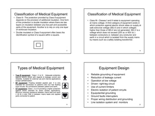
![Microshock due to Surrounding Equipment Codes and Standards
• Two wire table lamp • A code is a document that contains mandatory requirements. It uses the
word shall. is generally adopted into law by authority that has
is next to the patient jurisdiction.
bed. • A standard is a document that contains mandatory requirements, but
compliance tends to be voluntary.
• Saline filled catheter
• FDA: U.S. Food and Drug Administration
is used to measure • IEC: International Electrotechnical Committee
BP and pressure • NFPA: National Fire Protection Association
monitor is grounded. • ANSI: American National Standards Institute
• Saline is good • AAMI: Advancement of Medical Instrumentation
• BSI: British Standards Institute
conductor.
• ISO: International Organization for Standardization
I=
240 • Patient touches lamp • ECRI: Emergency Care Research Institute
(100k )2 + 1
2
case. • HEMA: Health Industry Manufacturers Association
2π .50.2500 x10
−12
• Fibrillation may • NEMA: National Electrical Manufacturers Association
= 189µA • NEC: National Electrical Code
occur.
13 14
Important Codes and Standards Classification of Medical Equipment
• IEC: International Electrotechnical Committee • Class I[ No Symbol]:- equipment in which protection against
electric shock does not rely solely on basic insulation but also
provided by connecting all accessible conductive parts to the
• NFPA 99: Standards for Health Care Facilities. protective earth conductor of the mains wiring. So, these parts
cannot become live in the case of failure of basic insulation.
• ANSI/AAMI ES1-1993: Safe Current Limits for • Protective earth conductor is that conductor to be connected
Electromedical Apparatus. between the protective earth terminal and external protective
earthing system. For flexible detachable supply cables, R< 0.1Ω
[ yellow, green, Y/ G sheets].
• BS 5724: Electrical Safety of Medical Equipment. • Max resistance between protective earth plug pin and protective
conductive parts is 0.2 Ω.
15 16](https://image.slidesharecdn.com/lect-4-oberm-electsafetymedequip-110708011516-phpapp02/85/Lect-4-ober-m-elect-safetymedequip-4-320.jpg)

Electrical safety is important for medical equipment due to the risks of electric shock and electrocution. The physiological effects of electric current on the human body can range from muscle cramps and respiratory arrest to ventricular fibrillation and burns, depending on the current level. Proper grounding and leakage current standards help reduce risks from macroshock and microshock that could endanger patients and medical staff.


