Downloaded 271 times


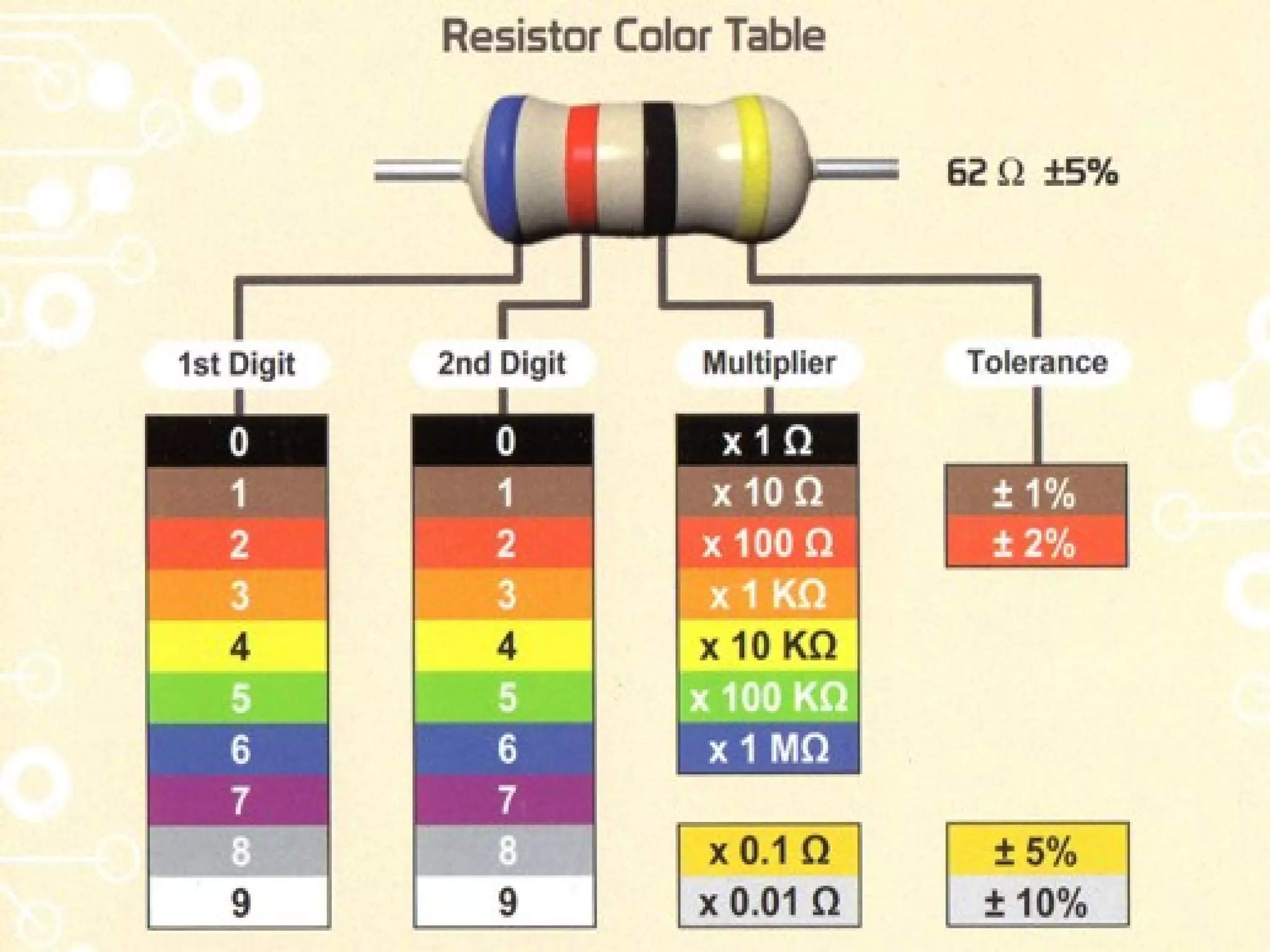
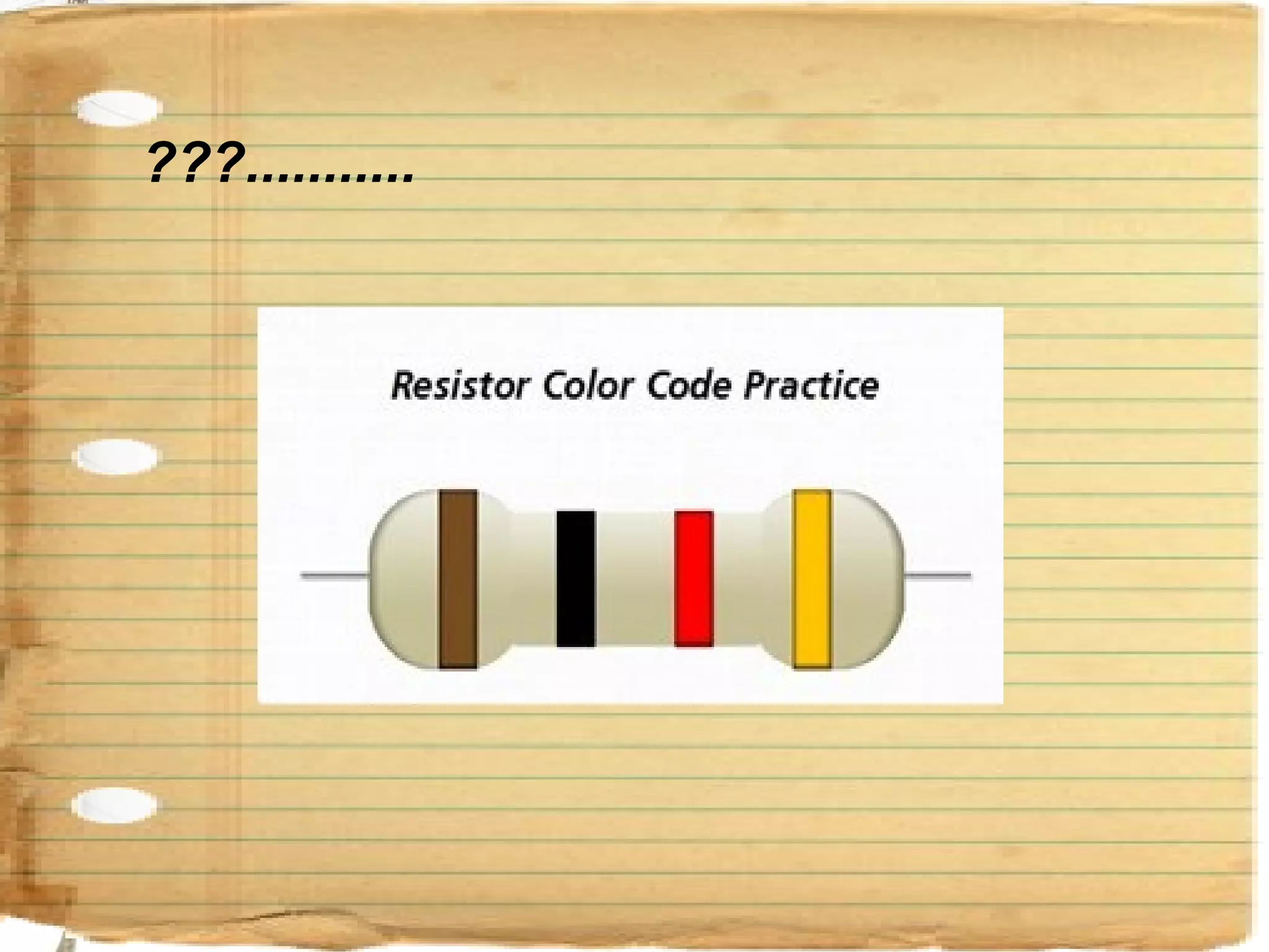
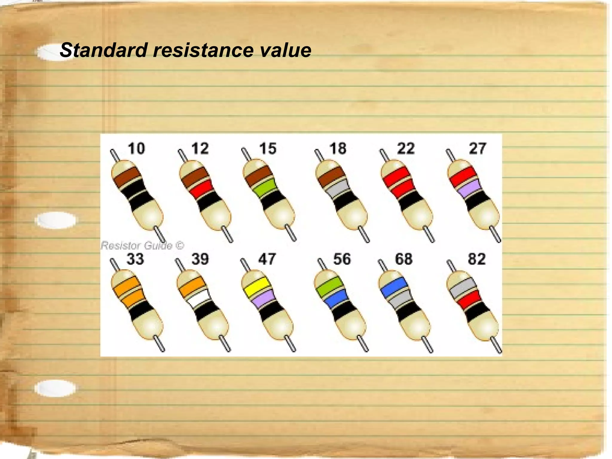

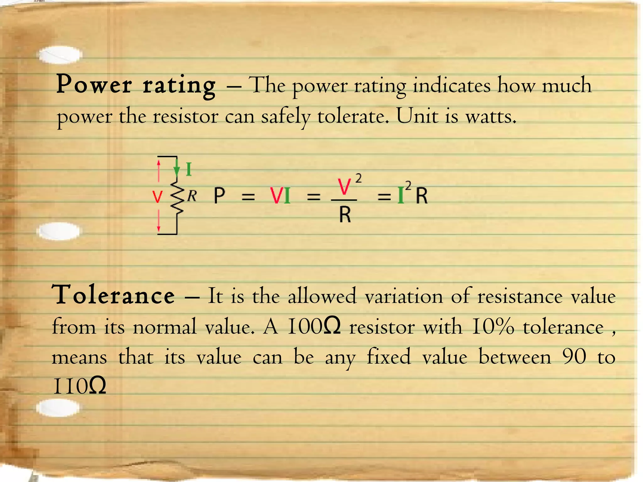


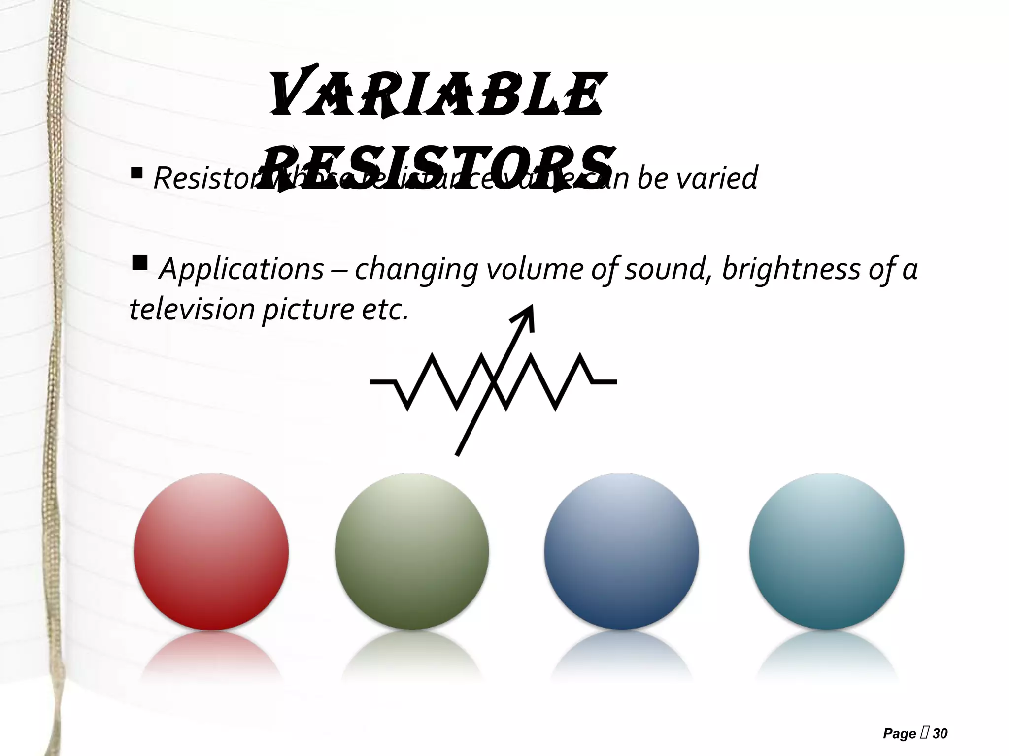

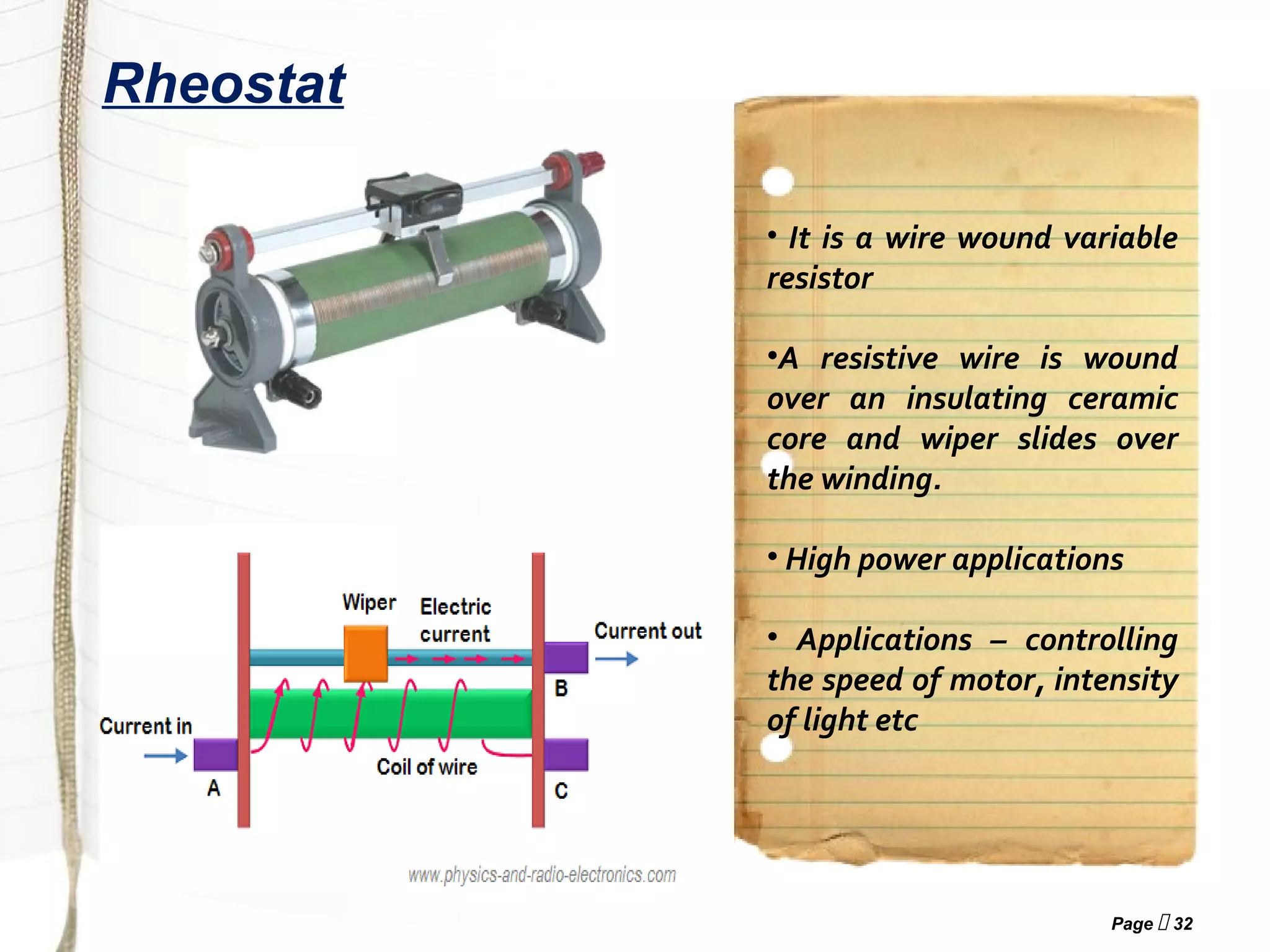


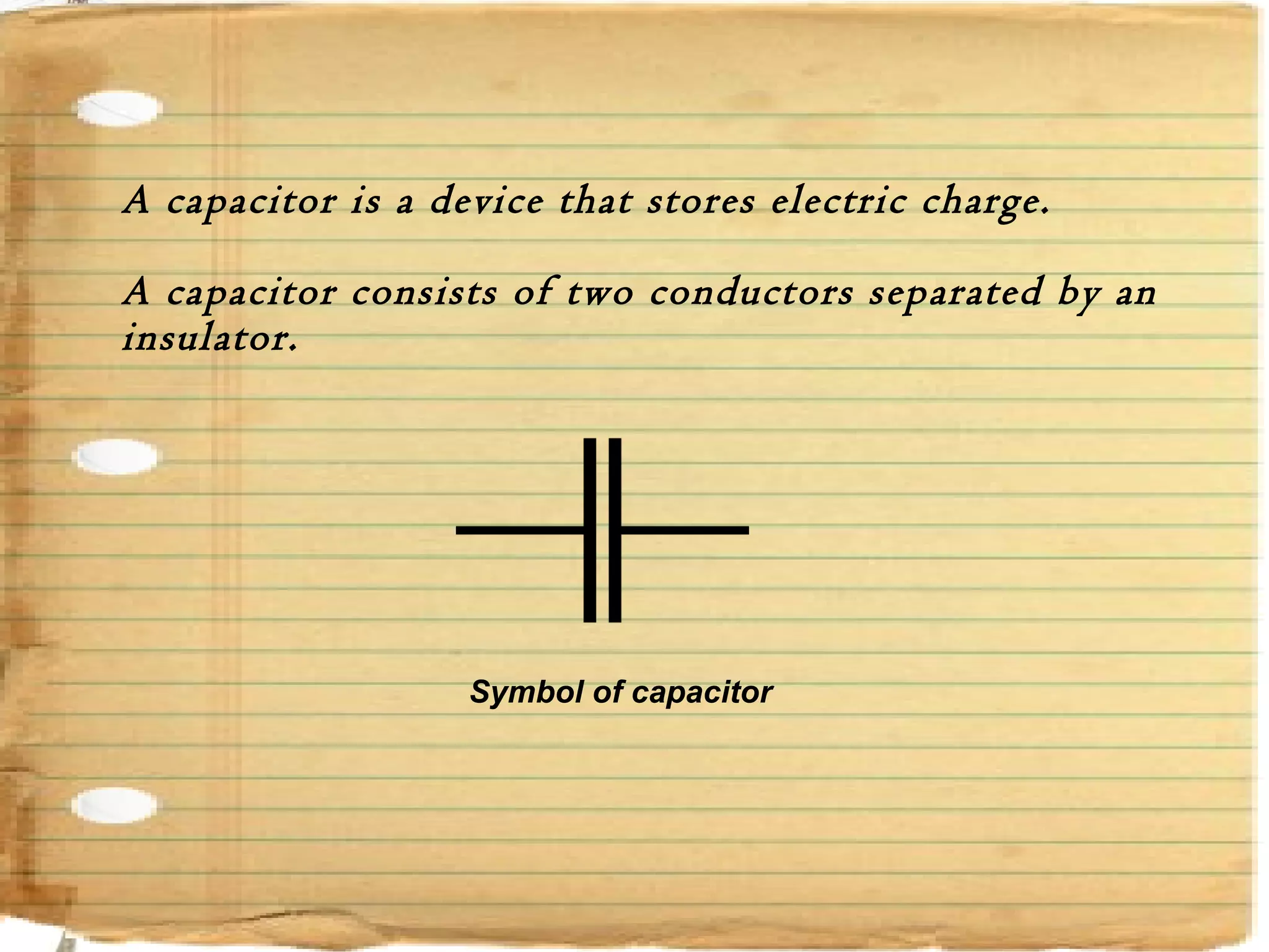
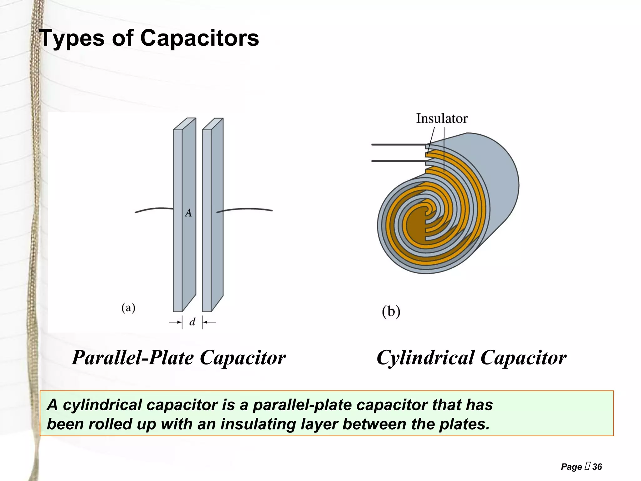


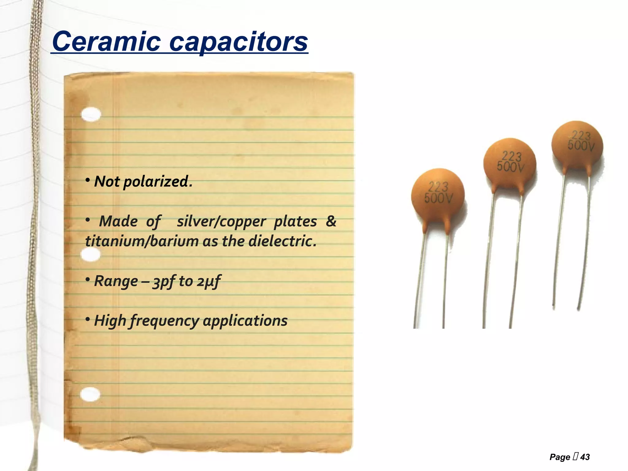
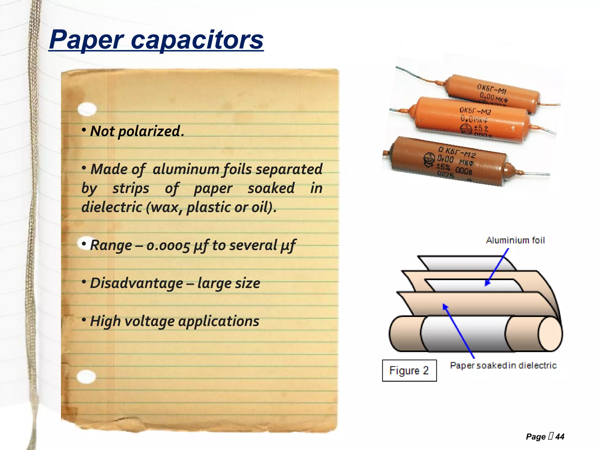


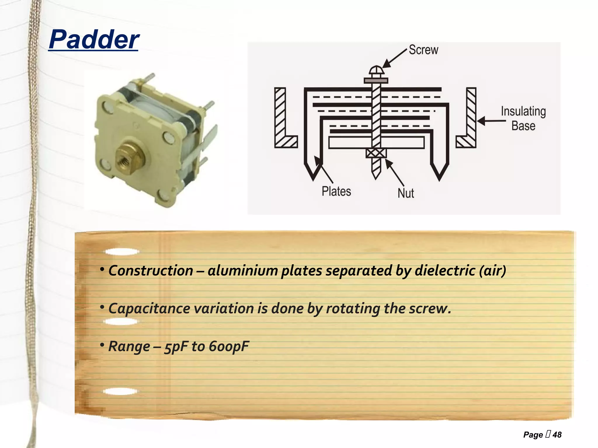


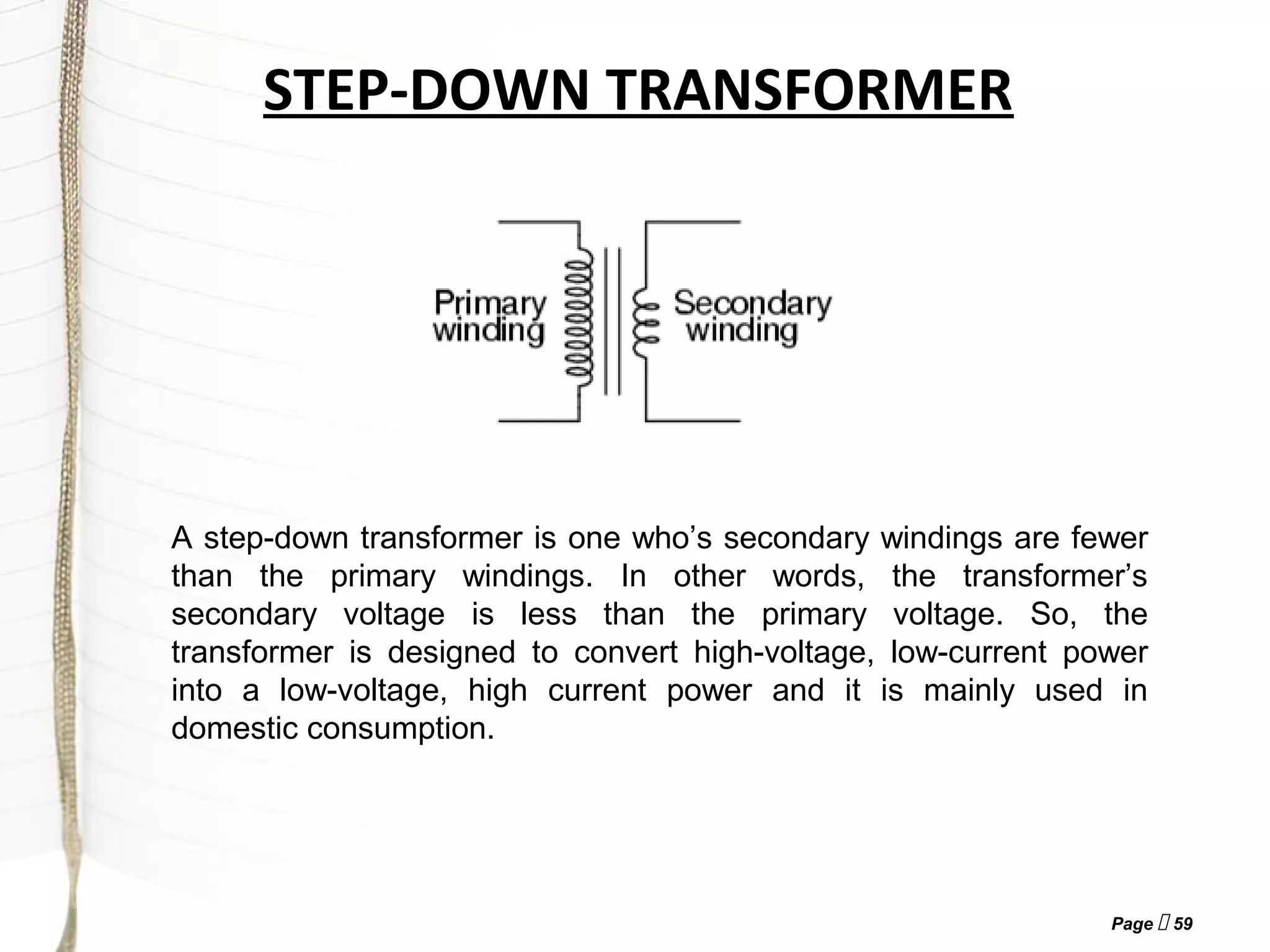
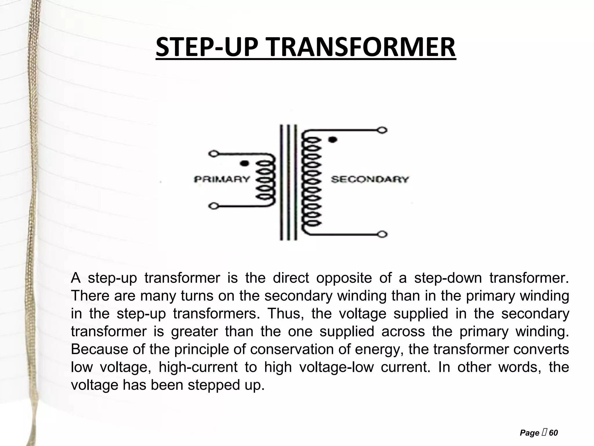


The document provides an introduction to electronic passive components. It discusses resistors, capacitors, inductors, and transformers. Resistors are electronic components that oppose the flow of current and come in fixed and variable types. Capacitors are components that store electric charge and also come in fixed and variable types. Inductors are coils of wire that oppose changes in current flow. Transformers are made of two coils of wire wound on a core and transfer energy from one circuit to another through mutual induction. The document provides details on various types of these components, their construction, properties, and applications.


