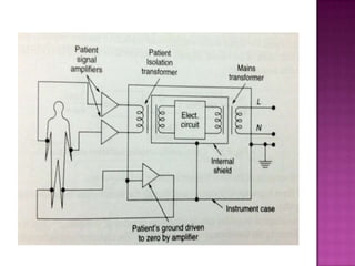
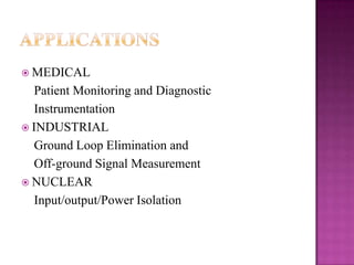
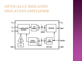
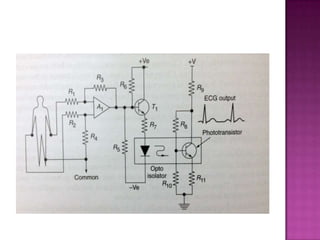
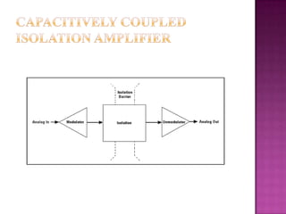
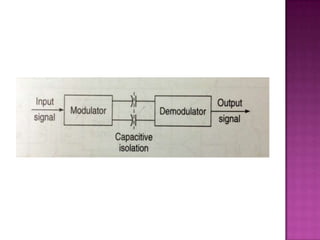
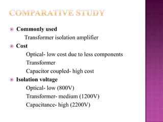
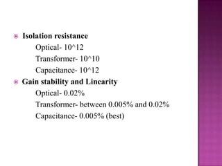
 Isolation

amplifiers provide electrical isolation
and an electrical safety barrier.
 They protect the patients from leakage
currents.
 They break the ohmic continuity of electrical
signals between input and output.
 Isolated power supplies are provided for both
the input and output stages.
 Used to amplify low level signals.
Three types of methods are used to design isolation
amplifier




Transformer isolation
Optical isolation
Capacitive isolation
It uses either frequency modulated or a pulse
width modulated carrier signal.
 Internally it has 20KHz oscillator, transformer,
rectifier and filter to provide supplies for each
isolated stages.
 Rectifier- input to primary OPAMP.
 Transformer- couples the supply.
 Oscillator – input to secondary OPAMP.
 A low pass filter is used to remove the other
frequency components.






High common mode rejection ratio
High linearity
High accuracy
 MEDICAL

Patient Monitoring and Diagnostic
Instrumentation
 INDUSTRIAL
Ground Loop Elimination and
Off-ground Signal Measurement
 NUCLEAR
Input/output/Power Isolation
 The

biological signal is converted into a light
signal by LED for further process.
 It has patient circuit which is the input circuit
and a phototransistor which forms the output
circuit.
 Each circuit is battery driven.
 The input circuit converts the signal to light
and the output circuit converts the light back to
signal.
Original frequency and amplitude is obtained.
 High linearity.
 No modulator or demodulator is needed as it
couples optically.
 Improves patient safety

 INDUSTRIAL PROCESS

CONTROL

 DATA ACQUISITION
 INTERFACE

ELEMENT
 BIOMEDICAL MEASUREMENTS
 PATIENT MONITORING
 TEST EQUIPMENT
 CURRENT SHUNT MEASUREMENT
 GROUND-LOOP ELIMINATION
 SCR CONTROLS
It uses digital encoding of the input voltage and
frequency modulation.
 The input voltage is converted to proportional
charge on the switched capacitor.
 It has modulator and demodulator circuits.
 The signals are sent across a differential capacitive
barrier.
 Separate supplies are given for both sides.

Ripple noises are removed.
 It avoids device noise, radiated noise and
conducted noise.
 High immunity to magnetic noises.
 Useful for analog systems.
 Has high gain stability and linearity.








DATA ACQUISITION
INTERFACE ELEMENT
PATIENT MONITORING
ECG
EEG






Commonly used
Transformer isolation amplifier
Cost
Optical- low cost due to less components
Transformer
Capacitor coupled- high cost
Isolation voltage
Optical- low (800V)
Transformer- medium (1200V)
Capacitance- high (2200V)




Isolation resistance
Optical- 10^12
Transformer- 10^10
Capacitance- 10^12
Gain stability and Linearity
Optical- 0.02%
Transformer- between 0.005% and 0.02%
Capacitance- 0.005% (best)
Isolation amplifier
Isolation amplifier
Isolation amplifier

Isolation amplifier

  • 2.
     Isolation amplifiers provideelectrical isolation and an electrical safety barrier.  They protect the patients from leakage currents.  They break the ohmic continuity of electrical signals between input and output.  Isolated power supplies are provided for both the input and output stages.  Used to amplify low level signals.
  • 4.
    Three types ofmethods are used to design isolation amplifier    Transformer isolation Optical isolation Capacitive isolation
  • 6.
    It uses eitherfrequency modulated or a pulse width modulated carrier signal.  Internally it has 20KHz oscillator, transformer, rectifier and filter to provide supplies for each isolated stages.  Rectifier- input to primary OPAMP.  Transformer- couples the supply.  Oscillator – input to secondary OPAMP.  A low pass filter is used to remove the other frequency components. 
  • 7.
       High common moderejection ratio High linearity High accuracy
  • 9.
     MEDICAL Patient Monitoringand Diagnostic Instrumentation  INDUSTRIAL Ground Loop Elimination and Off-ground Signal Measurement  NUCLEAR Input/output/Power Isolation
  • 11.
     The biological signalis converted into a light signal by LED for further process.  It has patient circuit which is the input circuit and a phototransistor which forms the output circuit.  Each circuit is battery driven.  The input circuit converts the signal to light and the output circuit converts the light back to signal.
  • 13.
    Original frequency andamplitude is obtained.  High linearity.  No modulator or demodulator is needed as it couples optically.  Improves patient safety 
  • 14.
     INDUSTRIAL PROCESS CONTROL DATA ACQUISITION  INTERFACE ELEMENT  BIOMEDICAL MEASUREMENTS  PATIENT MONITORING  TEST EQUIPMENT  CURRENT SHUNT MEASUREMENT  GROUND-LOOP ELIMINATION  SCR CONTROLS
  • 16.
    It uses digitalencoding of the input voltage and frequency modulation.  The input voltage is converted to proportional charge on the switched capacitor.  It has modulator and demodulator circuits.  The signals are sent across a differential capacitive barrier.  Separate supplies are given for both sides. 
  • 18.
    Ripple noises areremoved.  It avoids device noise, radiated noise and conducted noise.  High immunity to magnetic noises.  Useful for analog systems.  Has high gain stability and linearity. 
  • 19.
  • 20.
       Commonly used Transformer isolationamplifier Cost Optical- low cost due to less components Transformer Capacitor coupled- high cost Isolation voltage Optical- low (800V) Transformer- medium (1200V) Capacitance- high (2200V)
  • 21.
      Isolation resistance Optical- 10^12 Transformer-10^10 Capacitance- 10^12 Gain stability and Linearity Optical- 0.02% Transformer- between 0.005% and 0.02% Capacitance- 0.005% (best)