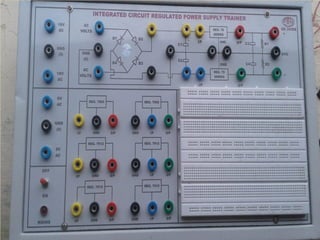
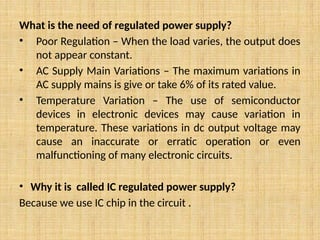
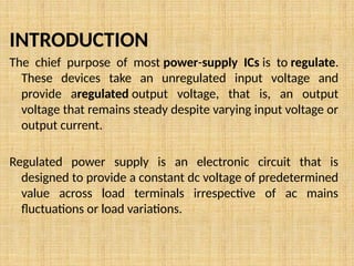
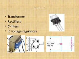
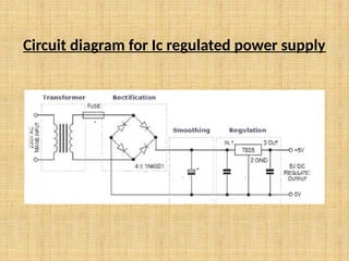
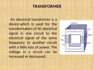
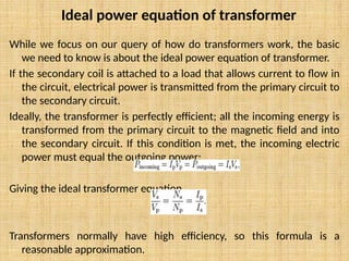
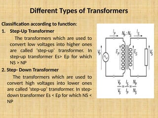
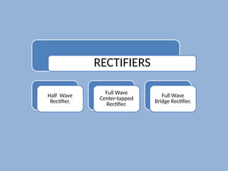
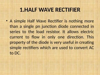
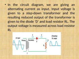
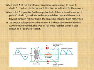
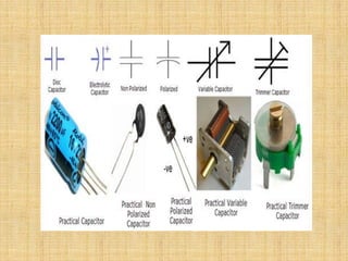
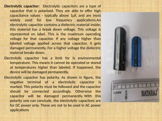
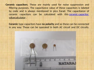
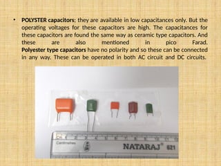
IC REGULATED
POWER SUPPLY
What is the need of regulated power supply?
• Poor Regulation – When the load varies, the output does
not appear constant.
• AC Supply Main Variations – The maximum variations in
AC supply mains is give or take 6% of its rated value.
• Temperature Variation – The use of semiconductor
devices in electronic devices may cause variation in
temperature. These variations in dc output voltage may
cause an inaccurate or erratic operation or even
malfunctioning of many electronic circuits.
• Why it is called IC regulated power supply?
Because we use IC chip in the circuit .
INTRODUCTION
The chief purpose of most power-supply ICs is to regulate.
These devices take an unregulated input voltage and
provide aregulated output voltage, that is, an output
voltage that remains steady despite varying input voltage or
output current.
Regulated power supply is an electronic circuit that is
designed to provide a constant dc voltage of predetermined
value across load terminals irrespective of ac mains
fluctuations or load variations.
Main Components in circuit
• Transformer
• Rectifiers
• C-filters
• IC voltage regulators
Circuit diagram for Ic regulated power supply
TRANSFORMER
An electrical transformer is a
device which is used for the
transformation of AC electrical
signal in one circuit to the
electrical signal of the same
frequency in another circuit
with a little loss of power. The
voltage in a circuit can be
increased or decreased.
While we focus on our query of how do transformers work, the basic
we need to know is about the ideal power equation of transformer.
If the secondary coil is attached to a load that allows current to flow in
the circuit, electrical power is transmitted from the primary circuit to
the secondary circuit.
Ideally, the transformer is perfectly efficient; all the incoming energy is
transformed from the primary circuit to the magnetic field and into
the secondary circuit. If this condition is met, the incoming electric
power must equal the outgoing power:
Giving the ideal transformer equation
Transformers normally have high efficiency, so this formula is a
reasonable approximation.
Ideal power equation of transformer
Different Types of Transformers
Classification according to function:
1. Step-Up Transformer
The transformers which are used to
convert low voltages into higher ones
are called ‘step-up’ transformer. In
step-up transformer Es> Ep for which
NS > NP
2. Step- Down Transformer
The transformers which are used to
convert high voltages into lower ones
are called ‘step-up’ transformer. In step-
down transformer Es < Ep for which NS <
NP
Energy losses
1. Resistance of windings – the low resistance copper wire used
for the windings still has resistance and thereby contributes to
heat loss .
2. Flux leakage – the flux produced by the primary coil may not
be all linked to the secondary coil if the design of the core is
bad.
3. Eddy currents – the changing magnetic field not only induces
currents in the secondary coil but also currents in the iron core
itself. These currents flow in little circles in the iron core and
are called eddy currents. The eddy currents cause heat loss.
The heat loss, however, can be reduced by having the core
laminated.
RECTIFIERS
Half Wave
Rectifier.
Full Wave
Center-tapped
Rectifier.
Full Wave
Bridge Rectifier.
1.HALF WAVE RECTIFIER
• A simple Half Wave Rectifier is nothing more
than a single pn junction diode connected in
series to the load resistor. It allows electric
current to flow in only one direction. This
property of the diode is very useful in creating
simple rectifiers which are used to convert AC
to DC.
• In the circuit diagram, we are giving an
alternating current as input. Input voltage is
given to a step-down transformer and the
resulting reduced output of the transformer is
given to the diode ‘D’ and load resistor RL. The
output voltage is measured across load resistor
RL
ADVANTAGES OF HALF WAVE RECTIFIER
Economical: It is low in cost.
Simple Circuitry: The circuit of half wave rectifier is simple to design.
DISADVANTAGES OF HALF WAVE RECTIFIER
Low rectification Efficiency: The rectification efficiency of Half wave
rectifier is quite low, i.e. 40.6%. The main reason behind this is
power delivered by the circuit of half wave rectifier is only for the
duration of positive half of AC cycle.
High Ripple factor: Ripple factor is given by the ratio of the value of
AC current present in the output current of the rectifier and the
output dc current of the rectifier. The ripple factor in the case of
half wave rectifier is quite high which is undesirable
2.FULL WAVE RECTIFIER
• A full wave rectifier circuit produces an output voltage or
current which is purely DC or has some specified DC
component. Full wave rectifiers have some fundamental
advantages over their half wave rectifier counterparts.
The average (DC) output voltage is higher than for half
wave, the output of the full wave rectifier has much less
ripple than that of the half wave rectifier producing a
smoother output waveform. The full wave rectifier circuit
consists of two diodes connected to a single load
resistance (RL) with each diode taking it in turn to supply
current to the load
When point A of the transformer is positive with respect to point C,
diode D1 conducts in the forward direction as indicated by the arrows.
When point B is positive (in the negative half of the cycle) with respect to
point C, diode D2 conducts in the forward direction and the current
flowing through resistor R is in the same direction for both half-cycles.
As the output voltage across the resistor R is the pharos sum of the two
waveforms combined, this type of full wave rectifier circuit is also
known as a “bi-phase” circuit.
3.THE FULL WAVE BRIDGE RECTIFIER
• Another type of circuit that produces the
same output waveform as the full wave
rectifier circuit above, is that of the Full Wave
Bridge Rectifier. This type of single phase
rectifier uses four individual rectifying diodes
connected in a closed loop “bridge”
configuration to produce the desired output.
The four diodes
labeled D1 to D4 are
arranged in “series pairs”
with only two diodes
conducting current during
each half cycle.
During the positive half cycle
of the supply,
diodes D1 and D2 conduct
in series while
diodes D3 and D4 are
reverse biased and the
current flows through the
load.
Key Differences Between Half Wave and Full Wave Rectifier
1. The significant key difference between half wave and full wave rectifier is
efficiency. Half wave rectifier is a low-efficiency rectifier while the full wave is
a high-efficiency rectifier. Thus, it is always better to use full wave when we
are working on the highly efficient application.
2. The centre tapping also differs in half wave and full wave rectifier. Half wave
rectifier does not require centre tapping while full wave requires centre
tapping.
3. The requirement of components varies in Half Wave and Full Wave Rectifier.
Full wave requires more electronic components as compared to half wave.
Thus, full wave rectifier is costly as compared to half wave. Full wave
requires double the number of diodes.
CAPACITORS TYPE
• Capacitors are filtering devices that are abundantly 5n electronic circuits
and having many applications.
• There are many different types of capacitor, but they all conform to the
same basic physical laws. These determine the basic way the capacitor
operates, its value, i.e. the amount of charge it will hold and hence its
capacitance.
• Although all capacitors work in essentially the same way, key differences in
the construction of different capacitor types makes an enormous difference
in their properties
• Some types of capacitor may bepolarised, i.e. they only tolerate voltages
across them in one direction. Other capacitor types are non-polarised and
can have voltages of either polarity across them.
• Typically the different types of capacitor are named after the type of
dielectric they contain. This gives a good indication of the general
properties they will exhibit and for what circuit functions they can be used.
Electrolytic capacitor: Electrolytic capacitors are a type of
capacitor that is polarised. They are able to offer high
capacitance values - typically above 1μF, and are most
widely used for low frequency applications.An
electrolytic capacitor contains a dielectric material inside;
this material has a break down voltage. This voltage is
represented on label. This is the maximum operating
voltage for that capacitor. If any voltage higher than
labeled voltage applied across that capacitor, it gets
damaged permanently. For a higher voltage the dielectric
material breaks down.
Electrolytic capacitor has a limit for is environmental
temperature. This means it cannot be operated or stored
at temperatures higher than labeled. If happened, the
device will be damaged permanently.
Electrolytic capacitor has polarity. As shown in figure, the
negative terminal of a electrolytic capacitor is
marked. This polarity must be followed and the capacitor
should be connected accordingly. Otherwise the
capacitor will be damaged permanently. With this
polarity one can conclude, the electrolytic capacitors are
for DC power only. These are not to be used in AC power
applications
Ceramic capacitors. These are mainly used for noise suppression and
filtering purposes. The capacitance value of these capacitors is labeled
by code and is always mentioned in pico Farad. The capacitance of
ceramic capacitors can be calculated with this ceramic capacitor
valuecalculator .
Ceramic type capacitors have no polarity and so these can be connected
in any way. These can be operated in both AC circuit and DC circuits.
• POLYSTER capacitors; they are available in low capacitances only. But the
operating voltages for these capacitors are high. The capacitances for
these capacitors are found the same way as ceramic type capacitors. And
these are also mentioned in pico Farad.
Polyester type capacitors have no polarity and so these can be connected
in any way. These can be operated in both AC circuit and DC circuits.
FILTER CIRCUITS
A filter circuit is device which removes the ac component of rectifier
output but allows dc component to reach the load.
Filter circuit should be installed between the rectifier and the load. A
filter circuit is generally combination of inductors (L),and
capacitors(C).The filtering action of L and C depends on the basic
electrical principles.
Types of filter circuits:
a) Capacitor filter
b) Choke input filter
c) Π filter
CAPACITOR FILTER
It consists of a capacitor C placed across the rectifier output in
parallel with load. The pulsating direct voltage of the rectifier is
applied across the capacitor. As the rectifier voltage increases, it
charges the capacitor and supplies current to load. At the end of
quarter cycle, the capacitor is charged to the peak value of
rectifier voltage. Now the rectifier voltage starts to decrease. As
this occurs the capacitor discharges through the load and
voltage across it decreases. The voltage across load will
decrease only slight because immediately next voltage peak
comes and recharge the capacitor. The process is repeated
again and again and very little ripple is left in the output.
IC VOLTAGE REGULATOR
The integrated circuit has various components such as resistors ,
capacitors, diodes, transistors etc. fabricated on small
semiconductor chip.
The IC voltage regulator is a device that is used to hold the output
voltage from a dc power supply constant as the input voltage and
load current changes.
Types of IC voltage regulators
a) Fixed positive voltage regulator
b) Fixed negative voltage regulator
Fixed positive voltage regulator
• For ICs within the 78xx family, the xx is replaced with two
digits, indicating the output voltage (for example, the 7805
has a 5-volt output, while the 7812 produces 12 volts).
• The 78xx line are positive voltage regulators: they produce
a voltage that is positive relative to a common ground.
• There are common configurations for 78xx ICs, including
7805 (5 V), 7806 (6 V), 7808 (8 V), 7809 (9 V), 7810 (10 V),
7812 (12 V), 7815 (15 V), 7818 (18 V), and 7824 (24 V)
versions.
• The 7805 is the most common, as its regulated 5-volt
supply provides a convenient power source .
Fixed negative voltage regulator
The 79xx devices have a similar "part number"
to "voltage output" scheme, but their outputs
are negative voltage.
For example 7905 is -5 V and 7912 is -12 V.
Advantages
• 78xx series ICs have built-in protection against
a circuit drawing too much current.
• They have protection against overheating and
short-circuits, making them robust in most
applications.
• 78xx series ICs do not require additional
components to set their output voltage
Disadvantages
• The input voltage must always be higher than the output
voltage by some minimum amount (typically 2.5 volts). This
can make these devices unsuitable for powering some devices
from certain types of power sources (for example, powering a
circuit that requires 5 volts using 6-volt batteries will not work
using a 7805)
• As the input voltage must always be higher than the output
voltage, this means that the total power (voltage multiplied by
current) going into the 78xx will be more than the output
power provided. The difference is dissipated as heat. This
means both that for some applications an adequate heatsink
must be provided
APPLICATIONS OF IC REGULATED POWER SUPPLY
1. Mobile Phone power adaptors
2. Various amplifiers and oscillators
3. It is much more accurate than zener diode
4. There is a built in overload protection
5. It has overheating protection. If the internal
temperature become excessive, it shuts off
until the temperature is reduced, at which
point it will start up again.
EXPERIMENT
Aim: To design and assemble an integrated circuit regulated power supply with
both polarities.
Apparatus: Four diodes, capacitor, resistor, 7805 Voltage regulator, 7905 Voltage
regulator, connecting wires, step down transformer, bread board.
Procedure:
• Connect the circuit using breadboard with proper connections.
• Now connect the digital multimeter across output.
• We will observe the output voltage as +5= Volts and -5 Volts.
• Similarly connect the regulator 7812 and 7912 in circuit instead of 7805 and
7905 and note the readings.
• We observe the output +12 volts and -12 vots respectively.
•
Precautions
• Connections should be tight.
• Connections should be correct.
• Ic should be used carefully.
IC REGULATED POWER SUPPLY MSC 2ND YEAR ELECTRONICS

IC REGULATED POWER SUPPLY MSC 2ND YEAR ELECTRONICS

  • 1.
  • 3.
    What is theneed of regulated power supply? • Poor Regulation – When the load varies, the output does not appear constant. • AC Supply Main Variations – The maximum variations in AC supply mains is give or take 6% of its rated value. • Temperature Variation – The use of semiconductor devices in electronic devices may cause variation in temperature. These variations in dc output voltage may cause an inaccurate or erratic operation or even malfunctioning of many electronic circuits. • Why it is called IC regulated power supply? Because we use IC chip in the circuit .
  • 4.
    INTRODUCTION The chief purposeof most power-supply ICs is to regulate. These devices take an unregulated input voltage and provide aregulated output voltage, that is, an output voltage that remains steady despite varying input voltage or output current. Regulated power supply is an electronic circuit that is designed to provide a constant dc voltage of predetermined value across load terminals irrespective of ac mains fluctuations or load variations.
  • 5.
    Main Components incircuit • Transformer • Rectifiers • C-filters • IC voltage regulators
  • 6.
    Circuit diagram forIc regulated power supply
  • 7.
    TRANSFORMER An electrical transformeris a device which is used for the transformation of AC electrical signal in one circuit to the electrical signal of the same frequency in another circuit with a little loss of power. The voltage in a circuit can be increased or decreased.
  • 8.
    While we focuson our query of how do transformers work, the basic we need to know is about the ideal power equation of transformer. If the secondary coil is attached to a load that allows current to flow in the circuit, electrical power is transmitted from the primary circuit to the secondary circuit. Ideally, the transformer is perfectly efficient; all the incoming energy is transformed from the primary circuit to the magnetic field and into the secondary circuit. If this condition is met, the incoming electric power must equal the outgoing power: Giving the ideal transformer equation Transformers normally have high efficiency, so this formula is a reasonable approximation. Ideal power equation of transformer
  • 9.
    Different Types ofTransformers Classification according to function: 1. Step-Up Transformer The transformers which are used to convert low voltages into higher ones are called ‘step-up’ transformer. In step-up transformer Es> Ep for which NS > NP 2. Step- Down Transformer The transformers which are used to convert high voltages into lower ones are called ‘step-up’ transformer. In step- down transformer Es < Ep for which NS < NP
  • 10.
    Energy losses 1. Resistanceof windings – the low resistance copper wire used for the windings still has resistance and thereby contributes to heat loss . 2. Flux leakage – the flux produced by the primary coil may not be all linked to the secondary coil if the design of the core is bad. 3. Eddy currents – the changing magnetic field not only induces currents in the secondary coil but also currents in the iron core itself. These currents flow in little circles in the iron core and are called eddy currents. The eddy currents cause heat loss. The heat loss, however, can be reduced by having the core laminated.
  • 11.
  • 12.
    1.HALF WAVE RECTIFIER •A simple Half Wave Rectifier is nothing more than a single pn junction diode connected in series to the load resistor. It allows electric current to flow in only one direction. This property of the diode is very useful in creating simple rectifiers which are used to convert AC to DC.
  • 13.
    • In thecircuit diagram, we are giving an alternating current as input. Input voltage is given to a step-down transformer and the resulting reduced output of the transformer is given to the diode ‘D’ and load resistor RL. The output voltage is measured across load resistor RL
  • 14.
    ADVANTAGES OF HALFWAVE RECTIFIER Economical: It is low in cost. Simple Circuitry: The circuit of half wave rectifier is simple to design. DISADVANTAGES OF HALF WAVE RECTIFIER Low rectification Efficiency: The rectification efficiency of Half wave rectifier is quite low, i.e. 40.6%. The main reason behind this is power delivered by the circuit of half wave rectifier is only for the duration of positive half of AC cycle. High Ripple factor: Ripple factor is given by the ratio of the value of AC current present in the output current of the rectifier and the output dc current of the rectifier. The ripple factor in the case of half wave rectifier is quite high which is undesirable
  • 15.
    2.FULL WAVE RECTIFIER •A full wave rectifier circuit produces an output voltage or current which is purely DC or has some specified DC component. Full wave rectifiers have some fundamental advantages over their half wave rectifier counterparts. The average (DC) output voltage is higher than for half wave, the output of the full wave rectifier has much less ripple than that of the half wave rectifier producing a smoother output waveform. The full wave rectifier circuit consists of two diodes connected to a single load resistance (RL) with each diode taking it in turn to supply current to the load
  • 16.
    When point Aof the transformer is positive with respect to point C, diode D1 conducts in the forward direction as indicated by the arrows. When point B is positive (in the negative half of the cycle) with respect to point C, diode D2 conducts in the forward direction and the current flowing through resistor R is in the same direction for both half-cycles. As the output voltage across the resistor R is the pharos sum of the two waveforms combined, this type of full wave rectifier circuit is also known as a “bi-phase” circuit.
  • 17.
    3.THE FULL WAVEBRIDGE RECTIFIER • Another type of circuit that produces the same output waveform as the full wave rectifier circuit above, is that of the Full Wave Bridge Rectifier. This type of single phase rectifier uses four individual rectifying diodes connected in a closed loop “bridge” configuration to produce the desired output.
  • 18.
    The four diodes labeledD1 to D4 are arranged in “series pairs” with only two diodes conducting current during each half cycle. During the positive half cycle of the supply, diodes D1 and D2 conduct in series while diodes D3 and D4 are reverse biased and the current flows through the load.
  • 19.
    Key Differences BetweenHalf Wave and Full Wave Rectifier 1. The significant key difference between half wave and full wave rectifier is efficiency. Half wave rectifier is a low-efficiency rectifier while the full wave is a high-efficiency rectifier. Thus, it is always better to use full wave when we are working on the highly efficient application. 2. The centre tapping also differs in half wave and full wave rectifier. Half wave rectifier does not require centre tapping while full wave requires centre tapping. 3. The requirement of components varies in Half Wave and Full Wave Rectifier. Full wave requires more electronic components as compared to half wave. Thus, full wave rectifier is costly as compared to half wave. Full wave requires double the number of diodes.
  • 20.
    CAPACITORS TYPE • Capacitorsare filtering devices that are abundantly 5n electronic circuits and having many applications. • There are many different types of capacitor, but they all conform to the same basic physical laws. These determine the basic way the capacitor operates, its value, i.e. the amount of charge it will hold and hence its capacitance. • Although all capacitors work in essentially the same way, key differences in the construction of different capacitor types makes an enormous difference in their properties • Some types of capacitor may bepolarised, i.e. they only tolerate voltages across them in one direction. Other capacitor types are non-polarised and can have voltages of either polarity across them. • Typically the different types of capacitor are named after the type of dielectric they contain. This gives a good indication of the general properties they will exhibit and for what circuit functions they can be used.
  • 22.
    Electrolytic capacitor: Electrolyticcapacitors are a type of capacitor that is polarised. They are able to offer high capacitance values - typically above 1μF, and are most widely used for low frequency applications.An electrolytic capacitor contains a dielectric material inside; this material has a break down voltage. This voltage is represented on label. This is the maximum operating voltage for that capacitor. If any voltage higher than labeled voltage applied across that capacitor, it gets damaged permanently. For a higher voltage the dielectric material breaks down. Electrolytic capacitor has a limit for is environmental temperature. This means it cannot be operated or stored at temperatures higher than labeled. If happened, the device will be damaged permanently. Electrolytic capacitor has polarity. As shown in figure, the negative terminal of a electrolytic capacitor is marked. This polarity must be followed and the capacitor should be connected accordingly. Otherwise the capacitor will be damaged permanently. With this polarity one can conclude, the electrolytic capacitors are for DC power only. These are not to be used in AC power applications
  • 23.
    Ceramic capacitors. Theseare mainly used for noise suppression and filtering purposes. The capacitance value of these capacitors is labeled by code and is always mentioned in pico Farad. The capacitance of ceramic capacitors can be calculated with this ceramic capacitor valuecalculator . Ceramic type capacitors have no polarity and so these can be connected in any way. These can be operated in both AC circuit and DC circuits.
  • 24.
    • POLYSTER capacitors;they are available in low capacitances only. But the operating voltages for these capacitors are high. The capacitances for these capacitors are found the same way as ceramic type capacitors. And these are also mentioned in pico Farad. Polyester type capacitors have no polarity and so these can be connected in any way. These can be operated in both AC circuit and DC circuits.
  • 25.
    FILTER CIRCUITS A filtercircuit is device which removes the ac component of rectifier output but allows dc component to reach the load. Filter circuit should be installed between the rectifier and the load. A filter circuit is generally combination of inductors (L),and capacitors(C).The filtering action of L and C depends on the basic electrical principles. Types of filter circuits: a) Capacitor filter b) Choke input filter c) Π filter
  • 26.
    CAPACITOR FILTER It consistsof a capacitor C placed across the rectifier output in parallel with load. The pulsating direct voltage of the rectifier is applied across the capacitor. As the rectifier voltage increases, it charges the capacitor and supplies current to load. At the end of quarter cycle, the capacitor is charged to the peak value of rectifier voltage. Now the rectifier voltage starts to decrease. As this occurs the capacitor discharges through the load and voltage across it decreases. The voltage across load will decrease only slight because immediately next voltage peak comes and recharge the capacitor. The process is repeated again and again and very little ripple is left in the output.
  • 27.
    IC VOLTAGE REGULATOR Theintegrated circuit has various components such as resistors , capacitors, diodes, transistors etc. fabricated on small semiconductor chip. The IC voltage regulator is a device that is used to hold the output voltage from a dc power supply constant as the input voltage and load current changes. Types of IC voltage regulators a) Fixed positive voltage regulator b) Fixed negative voltage regulator
  • 28.
    Fixed positive voltageregulator • For ICs within the 78xx family, the xx is replaced with two digits, indicating the output voltage (for example, the 7805 has a 5-volt output, while the 7812 produces 12 volts). • The 78xx line are positive voltage regulators: they produce a voltage that is positive relative to a common ground. • There are common configurations for 78xx ICs, including 7805 (5 V), 7806 (6 V), 7808 (8 V), 7809 (9 V), 7810 (10 V), 7812 (12 V), 7815 (15 V), 7818 (18 V), and 7824 (24 V) versions. • The 7805 is the most common, as its regulated 5-volt supply provides a convenient power source .
  • 29.
    Fixed negative voltageregulator The 79xx devices have a similar "part number" to "voltage output" scheme, but their outputs are negative voltage. For example 7905 is -5 V and 7912 is -12 V.
  • 30.
    Advantages • 78xx seriesICs have built-in protection against a circuit drawing too much current. • They have protection against overheating and short-circuits, making them robust in most applications. • 78xx series ICs do not require additional components to set their output voltage
  • 31.
    Disadvantages • The inputvoltage must always be higher than the output voltage by some minimum amount (typically 2.5 volts). This can make these devices unsuitable for powering some devices from certain types of power sources (for example, powering a circuit that requires 5 volts using 6-volt batteries will not work using a 7805) • As the input voltage must always be higher than the output voltage, this means that the total power (voltage multiplied by current) going into the 78xx will be more than the output power provided. The difference is dissipated as heat. This means both that for some applications an adequate heatsink must be provided
  • 32.
    APPLICATIONS OF ICREGULATED POWER SUPPLY 1. Mobile Phone power adaptors 2. Various amplifiers and oscillators 3. It is much more accurate than zener diode 4. There is a built in overload protection 5. It has overheating protection. If the internal temperature become excessive, it shuts off until the temperature is reduced, at which point it will start up again.
  • 33.
    EXPERIMENT Aim: To designand assemble an integrated circuit regulated power supply with both polarities. Apparatus: Four diodes, capacitor, resistor, 7805 Voltage regulator, 7905 Voltage regulator, connecting wires, step down transformer, bread board. Procedure: • Connect the circuit using breadboard with proper connections. • Now connect the digital multimeter across output. • We will observe the output voltage as +5= Volts and -5 Volts. • Similarly connect the regulator 7812 and 7912 in circuit instead of 7805 and 7905 and note the readings. • We observe the output +12 volts and -12 vots respectively. • Precautions • Connections should be tight. • Connections should be correct. • Ic should be used carefully.