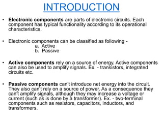
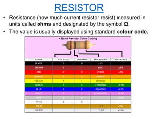
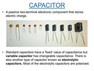
A
PRESENTATION
ON
"ELECTRONIC COMPONENTS"
BY
ARNAB BHAUMIK
CONTENTS
• INTRODUCTION
• RESISTOR
• CAPACITOR
• DIODE
• TRANSISTOR
• TRANSFORMER
• INTEGRATED CIRCUIT
• Electronic components are parts of electronic circuits. Each
component has typical functionality according to its operational
characteristics.
• Electronic components can be classified as following -
a. Active
b. Passive
• Active components rely on a source of energy. Active components
can also be used to amplify signals. Ex. - transistors, integrated
circuits etc.
• Passive components can't introduce net energy into the circuit.
They also can't rely on a source of power. As a consequence they
can't amplify signals, although they may increase a voltage or
current (such as is done by a transformer). Ex. - two-terminal
components such as resistors, capacitors, inductors, and
transformers.
INTRODUCTION
Various electronic components
RESISTOR
• A passive two-terminal electronic component that resists the
flow of current.
• Most of the resistors used in electronics have 'fixed' values,
but resistors can also be made which have a controlled,
variable resistance (Rheostat & Potentiometer).
• Symbol -
a. Fixed value resistor
b. Variable resistor (Rheostat)
c. Variable resistor (Potentiometer)
RESISTOR
• Resistance (how much current resistor resist) measured in
units called ohms and designated by the symbol Ω.
• The value is usually displayed using standard colour code.
CAPACITOR
• A passive two-terminal electronic component that stores
electric charge.
• Standard capacitors have a 'fixed' value of capacitance but
variable capacitor has changeable capacitance. There is
also another type of capacitor known as electrolytic
capacitors. Most of the electrolytic capacitors are polarized.
• Symbol -
• Capacitance is measured in units of Farad denoted by F.
• Larger capacitors like electrolytics usually display the actual
capacitance together with the unit (for example, 220 μF).
Smaller capacitors use a shorthand consisting of three
numeric digits, where the digits indicate the capacitance in pF
(calculated as XY × 10Z for digits XYZ).
CAPACITOR
DIODE
• A two-terminal electronic component that lets current flow in
only one direction.
• There are several types of diodes. Some of them are-
a. p-n juction diode
b. Zener diode
c. Light emitting diode (LED)
• a) p-n juction diode - When one side of a single-crystal
semiconductor doped with acceptors and the other side is
doped with donors, a p-n juction is produced. It is referred to as
a juction diode.
• Symbol-
DIODE
• b) Zener diode - Designed to have a very low reverse
breakdown (zener) voltage, at which they allow high current to
pass.
• Symbol -
DIODE
• c) Light-emitting diode (LED) - It is a special type of diode
that emits light when current passes through it.
• Symbol -
DIODE
DIODE AS RECTIFIER
• We have found that a semiconductor junction diode possesses
a low forward resistance & a high backward resistance. Such
diodes can therefore be used as rectifiers by which alternating
current (or voltage) is transformed into a direct current (or
voltage).
• Rectifiers are classified according to the period of conduction.
They are -
a. Half-wave rectifier
b. Full-wave rectifier
There is also a type of rectifier known as 'bridge rectifier'
which is actually a full-wave rectifier.
DIODE AS RECTIFIER
• a) Half-wave rectifier - Current can flow through the load resistance during
the positive half cycle of the input voltage.
For a full wave AC input, we are getting a half wave DC outout.
AC input waveforms Circuit diagram DC output waveforms
• b) Full-wave rectifier - A unidirectional current can flow through the load
resistance during the full cycle of the input voltage.
For a full wave AC input, we are getting a full wave DC outout.
AC input waveforms Circuit diagram DC output waveforms
DIODE AS RECTIFIER
• Bridge rectifier - It is actually a full-wave rectifier.
Circuit diagram
input & output waveforms
TRANSISTOR
• A three-terminal active electronic component used to amplify
and switch electronic signals and electrical power.
• By structure transistors can be categorized as following:
a. Bipolar junction transistor (BJT)
b. Field-effect transistor (FET)
TRANSISTOR
• a) BJT - A combination of two junction diodes, and is formed of
either a thin layer of p-type semiconductor sandwiched
between two n-type semiconductors (n–p–n transistor), or a
thin layer of n-type semiconductor sandwiched between two p-
type semiconductors (p–n–p transistor).
BJTs have three terminals, corresponding to the
three layers of semiconductor - an emitter, a base, and a
collector.
• b) FET - A unipolar transistor, uses either electrons (in n-
channel FET) or holes (in p-channel FET) for conduction. The
four terminals of the FET are named source, gate, drain, and
body (substrate).
FETs are divided into two families: junction FET (JFET)
and insulated gate FET (IGFET).
TRANSISTOR
• Symbol -
TRANSFORMER
• A passive electronic component that transfers electrical energy
between two or more circuits through electromagnetic
induction.
• Transformers can be classified in many ways, such as the
following:
a. Step-up
b. Step-down
c. Impedance matching
d. Centre tapped
TRANSFORMER
• Symbol -
Impedance matching Transformer
Centre tapped Transformer
TRANSFORMER
• Applications - Step-up transformers are used to increase or step-up
voltage before transmitting electrical energy over long distances through
wires.
Step-down transformers are also used extensively in
electronic products to decrease or step-down the supply voltage to a
level suitable for the low voltage circuits they contain.
For centre tapped transformers the difference lies in just the
fact that its secondary winding is divided into two parts, so two
individual voltages can be acquired across the two line ends.
INTEGRATED CIRCUIT
• An integrated circuit (IC),
sometimes called a chip or
microchip, is a
semiconductor wafer on
which thousands or millions
of tiny resistors, capacitors,
and transistors are
fabricated.
• Symbol -
INTEGRATED CIRCUIT
Generations
• In the early days of simple integrated circuits, the technology's large scale
limited each chip to only a few transistors, the design process was
relatively simple. As the technology progressed millions, then billions of
transistors could be placed on one chip, and good designs required
thorough planning, giving rise to new design methods.
• Applications - An IC can function as an amplifier, oscillator, timer, counter,
computer memory, or microprocessor. A particular IC is categorized as
either linear (analog) or digital, depending on its intended application.
THANK YOU

Electronic Components

  • 1.
  • 2.
    CONTENTS • INTRODUCTION • RESISTOR •CAPACITOR • DIODE • TRANSISTOR • TRANSFORMER • INTEGRATED CIRCUIT
  • 3.
    • Electronic componentsare parts of electronic circuits. Each component has typical functionality according to its operational characteristics. • Electronic components can be classified as following - a. Active b. Passive • Active components rely on a source of energy. Active components can also be used to amplify signals. Ex. - transistors, integrated circuits etc. • Passive components can't introduce net energy into the circuit. They also can't rely on a source of power. As a consequence they can't amplify signals, although they may increase a voltage or current (such as is done by a transformer). Ex. - two-terminal components such as resistors, capacitors, inductors, and transformers. INTRODUCTION
  • 4.
  • 5.
    RESISTOR • A passivetwo-terminal electronic component that resists the flow of current. • Most of the resistors used in electronics have 'fixed' values, but resistors can also be made which have a controlled, variable resistance (Rheostat & Potentiometer). • Symbol - a. Fixed value resistor b. Variable resistor (Rheostat) c. Variable resistor (Potentiometer)
  • 6.
    RESISTOR • Resistance (howmuch current resistor resist) measured in units called ohms and designated by the symbol Ω. • The value is usually displayed using standard colour code.
  • 7.
    CAPACITOR • A passivetwo-terminal electronic component that stores electric charge. • Standard capacitors have a 'fixed' value of capacitance but variable capacitor has changeable capacitance. There is also another type of capacitor known as electrolytic capacitors. Most of the electrolytic capacitors are polarized.
  • 8.
    • Symbol - •Capacitance is measured in units of Farad denoted by F. • Larger capacitors like electrolytics usually display the actual capacitance together with the unit (for example, 220 μF). Smaller capacitors use a shorthand consisting of three numeric digits, where the digits indicate the capacitance in pF (calculated as XY × 10Z for digits XYZ). CAPACITOR
  • 9.
    DIODE • A two-terminalelectronic component that lets current flow in only one direction. • There are several types of diodes. Some of them are- a. p-n juction diode b. Zener diode c. Light emitting diode (LED) • a) p-n juction diode - When one side of a single-crystal semiconductor doped with acceptors and the other side is doped with donors, a p-n juction is produced. It is referred to as a juction diode. • Symbol-
  • 10.
    DIODE • b) Zenerdiode - Designed to have a very low reverse breakdown (zener) voltage, at which they allow high current to pass. • Symbol -
  • 11.
    DIODE • c) Light-emittingdiode (LED) - It is a special type of diode that emits light when current passes through it. • Symbol -
  • 12.
    DIODE DIODE AS RECTIFIER •We have found that a semiconductor junction diode possesses a low forward resistance & a high backward resistance. Such diodes can therefore be used as rectifiers by which alternating current (or voltage) is transformed into a direct current (or voltage). • Rectifiers are classified according to the period of conduction. They are - a. Half-wave rectifier b. Full-wave rectifier There is also a type of rectifier known as 'bridge rectifier' which is actually a full-wave rectifier.
  • 13.
    DIODE AS RECTIFIER •a) Half-wave rectifier - Current can flow through the load resistance during the positive half cycle of the input voltage. For a full wave AC input, we are getting a half wave DC outout. AC input waveforms Circuit diagram DC output waveforms • b) Full-wave rectifier - A unidirectional current can flow through the load resistance during the full cycle of the input voltage. For a full wave AC input, we are getting a full wave DC outout. AC input waveforms Circuit diagram DC output waveforms
  • 14.
    DIODE AS RECTIFIER •Bridge rectifier - It is actually a full-wave rectifier. Circuit diagram input & output waveforms
  • 15.
    TRANSISTOR • A three-terminalactive electronic component used to amplify and switch electronic signals and electrical power. • By structure transistors can be categorized as following: a. Bipolar junction transistor (BJT) b. Field-effect transistor (FET)
  • 16.
    TRANSISTOR • a) BJT- A combination of two junction diodes, and is formed of either a thin layer of p-type semiconductor sandwiched between two n-type semiconductors (n–p–n transistor), or a thin layer of n-type semiconductor sandwiched between two p- type semiconductors (p–n–p transistor). BJTs have three terminals, corresponding to the three layers of semiconductor - an emitter, a base, and a collector. • b) FET - A unipolar transistor, uses either electrons (in n- channel FET) or holes (in p-channel FET) for conduction. The four terminals of the FET are named source, gate, drain, and body (substrate). FETs are divided into two families: junction FET (JFET) and insulated gate FET (IGFET).
  • 17.
  • 18.
    TRANSFORMER • A passiveelectronic component that transfers electrical energy between two or more circuits through electromagnetic induction. • Transformers can be classified in many ways, such as the following: a. Step-up b. Step-down c. Impedance matching d. Centre tapped
  • 19.
    TRANSFORMER • Symbol - Impedancematching Transformer Centre tapped Transformer
  • 20.
    TRANSFORMER • Applications -Step-up transformers are used to increase or step-up voltage before transmitting electrical energy over long distances through wires. Step-down transformers are also used extensively in electronic products to decrease or step-down the supply voltage to a level suitable for the low voltage circuits they contain. For centre tapped transformers the difference lies in just the fact that its secondary winding is divided into two parts, so two individual voltages can be acquired across the two line ends.
  • 21.
    INTEGRATED CIRCUIT • Anintegrated circuit (IC), sometimes called a chip or microchip, is a semiconductor wafer on which thousands or millions of tiny resistors, capacitors, and transistors are fabricated. • Symbol -
  • 22.
    INTEGRATED CIRCUIT Generations • Inthe early days of simple integrated circuits, the technology's large scale limited each chip to only a few transistors, the design process was relatively simple. As the technology progressed millions, then billions of transistors could be placed on one chip, and good designs required thorough planning, giving rise to new design methods. • Applications - An IC can function as an amplifier, oscillator, timer, counter, computer memory, or microprocessor. A particular IC is categorized as either linear (analog) or digital, depending on its intended application.
  • 23.