Downloaded 767 times
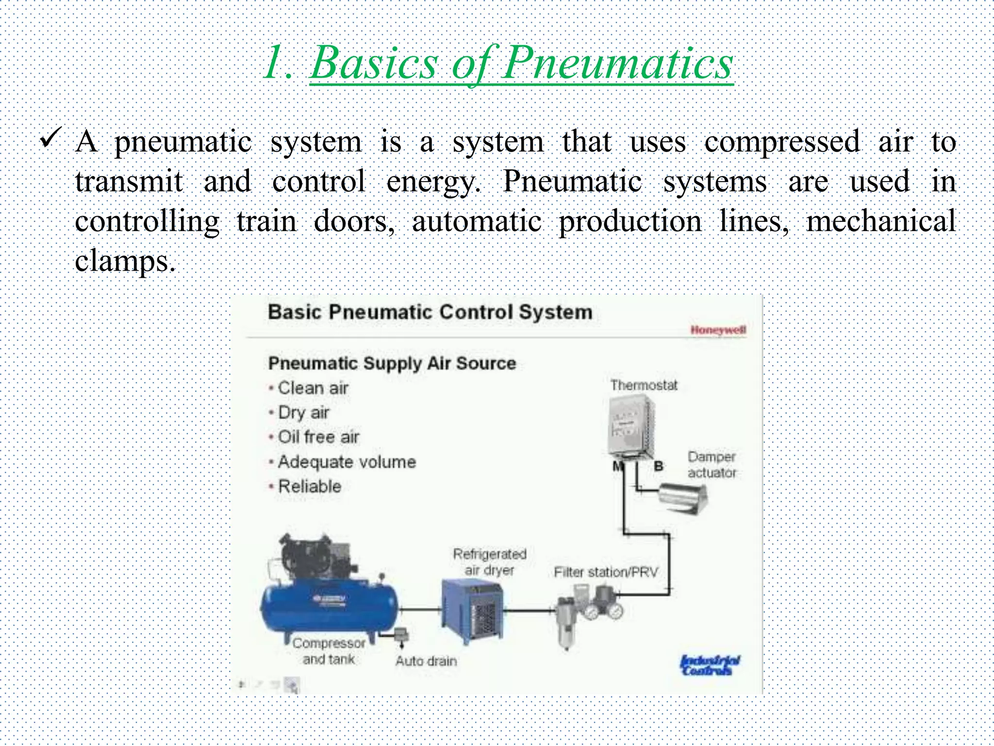
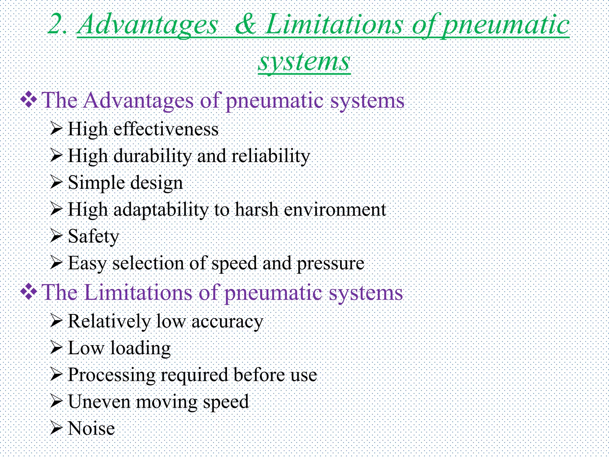

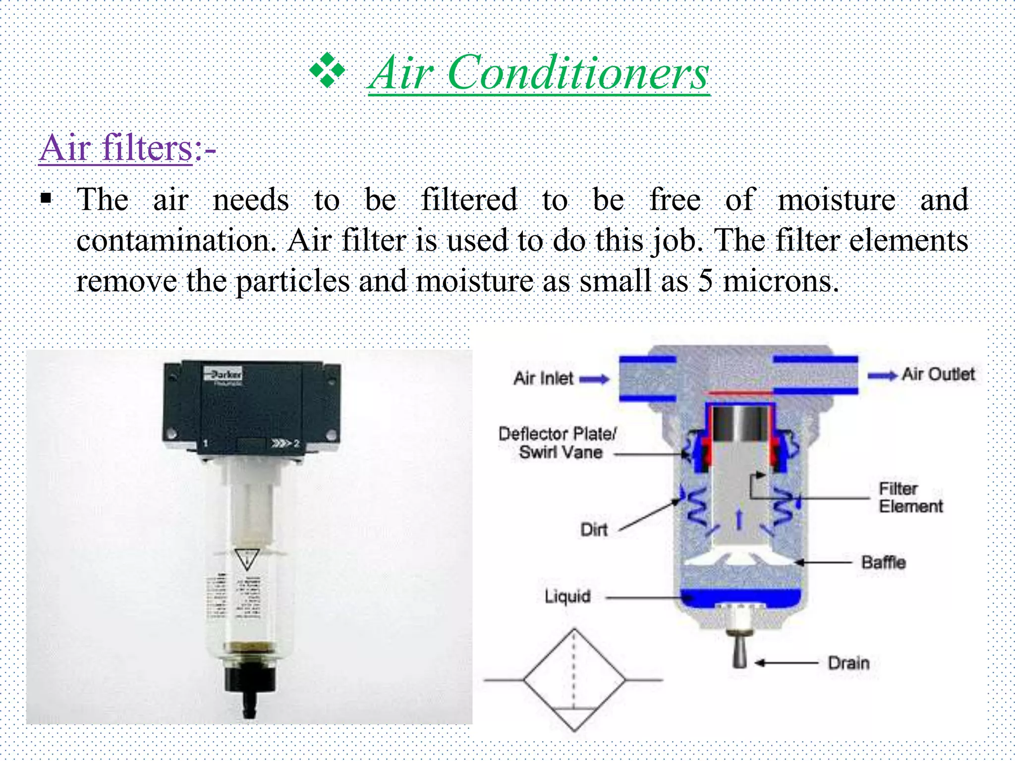
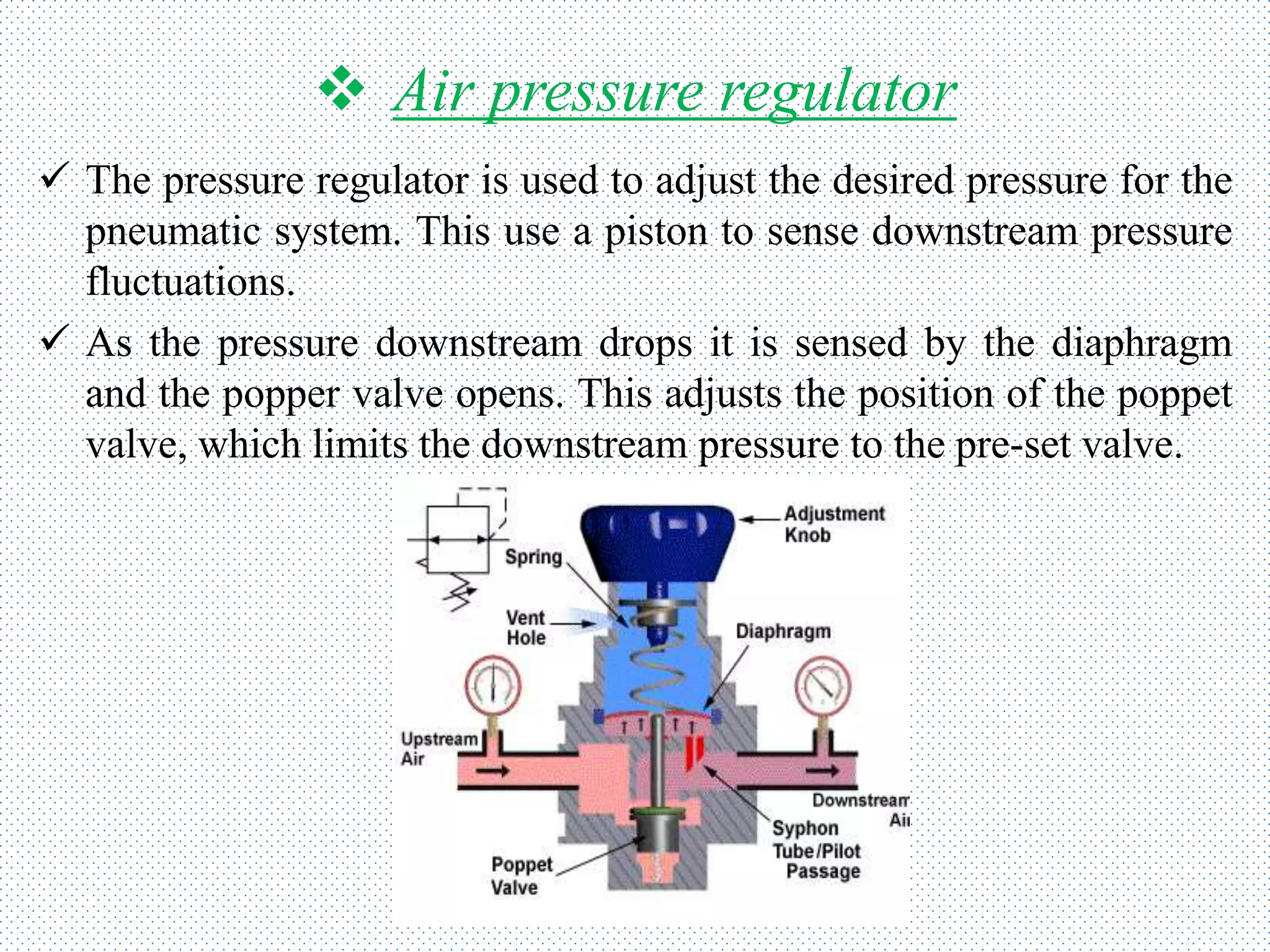
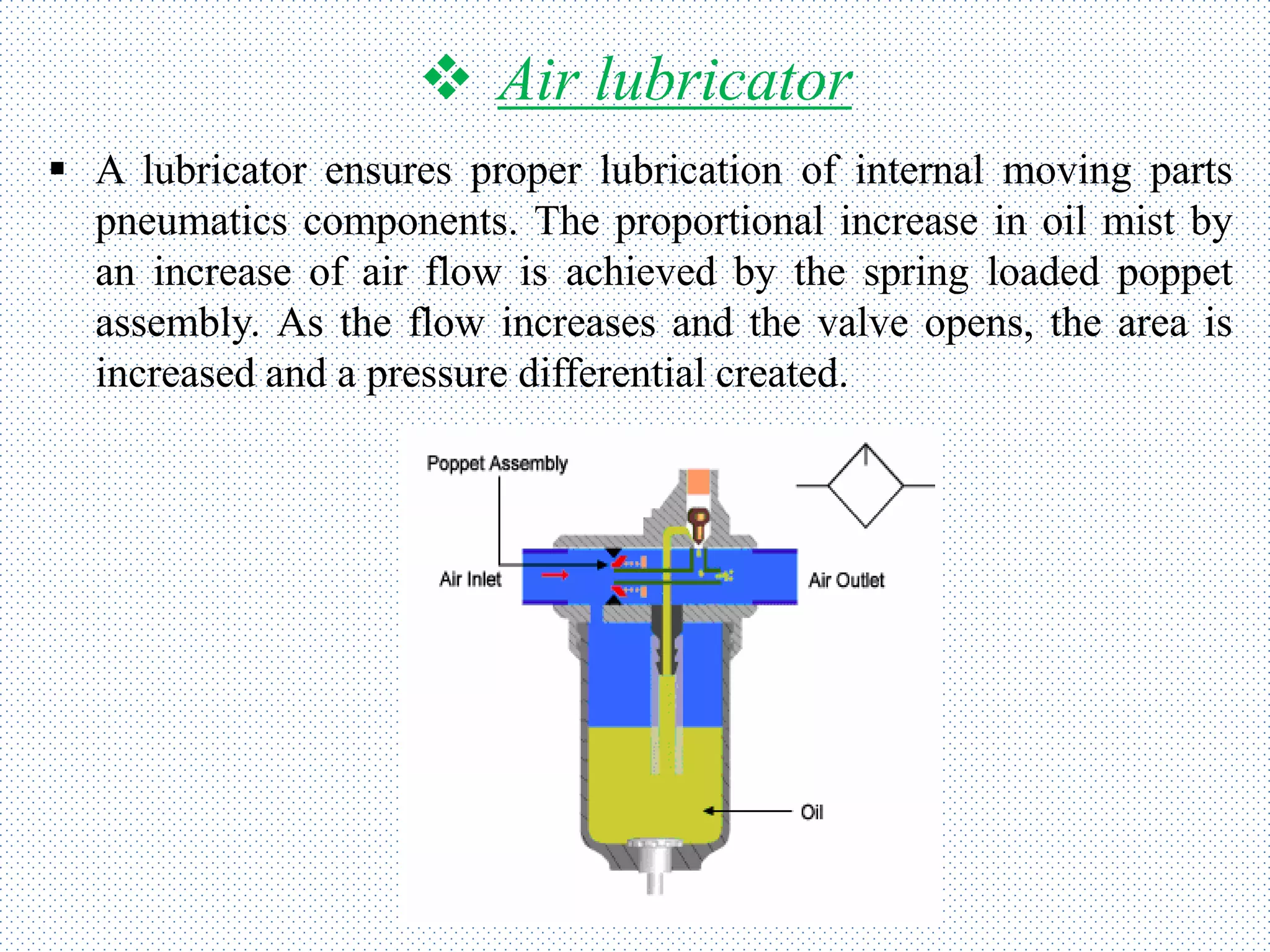
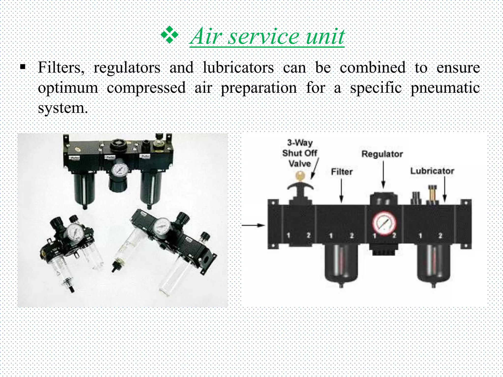


The document presents an overview of pneumatic control systems, including their basic principles, advantages, limitations, and essential components such as compressors, regulators, and valves. It details various types of pneumatic components and systems, emphasizing their applications in industries like automation and production. Additionally, it discusses the functionality and categorization of pneumatic valves and actuators.


