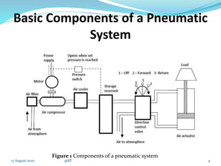
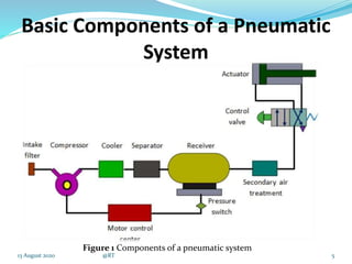
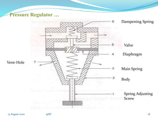
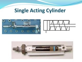
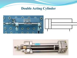
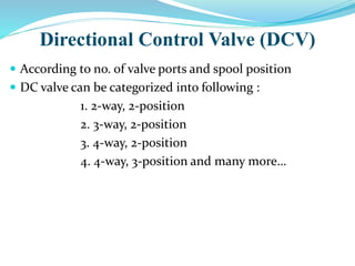
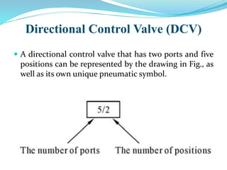
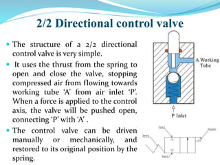
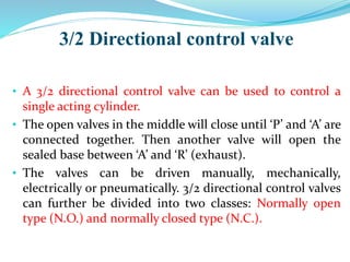
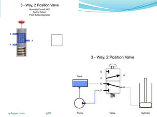
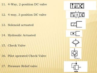
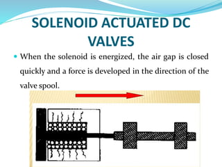
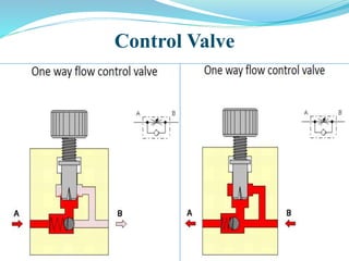
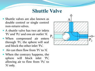
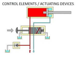
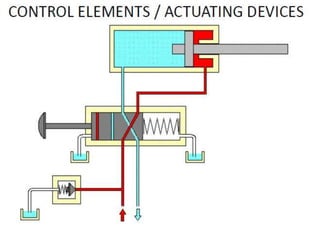
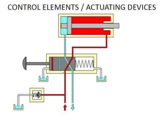
SlideShare a Scribd company logo
CHAPTER 6
INTRODUCTION to pneumatic system
13 August 2020 @RT 1
Prepared by : Prof. Rahul Thaker
Department of Mechanical Engineering
Alpha College of Engineering & Technology
Contents
 Introduction
 Basic Components of a Pneumatic System , Advantages ,
Disadvantages
 Main Pneumatic Components
 Compressors and
 Pressure regulating components.(FRL Unit)
 Directional control valves (DCVs)
 Execution components (cylinders)
 Solenoid Actuated Dc Valves
 Control Valve
213 August 2020 @RT
PNEUMATIC SYSTEMS
 A pneumatic system is a system that uses compressed air
to transmit and control energy. Pneumatic systems are
used in controlling train doors, automatic production
lines, mechanical clamps, etc.
313 August 2020 @RT
Basic Components of a Pneumatic
System
4
Figure 1 Components of a pneumatic system
13 August 2020 @RT
Basic Components of a Pneumatic
System
5
Figure 1 Components of a pneumatic system
13 August 2020 @RT
 Air filters: To filter out the contaminants from the air.
 Compressor: Compressed air is generated by using air compressors. Air
compressors are either diesel or electrically operated.
 Air cooler: During compression operation, air temperature increases.
Therefore coolers are used to reduce the temperature of the compressed air.
 Dryer: The water vapour or moisture in the air is separated from the air by
using a dryer.
 Control Valves: To regulate, control and monitor for control of direction
flow, pressure etc.
 Air Actuator: Air cylinders and motors are used to obtain the required
movements of mechanical elements of pneumatic system.
 Electric Motor: Transforms electrical energy into mechanical energy. It is
used to drive the compressor.
 Receiver tank: The compressed air coming from the compressor is stored
in the air receiver.
613 August 2020 @RT
Advantages of Pneumatic Systems
• High Effectiveness – use of compressed air in not restricted by
distance & can easily be transported.
• High durability and reliability – Extremely durable and not damaged
easily.
• Simple Design - more suitable for use in simple automatic control
systems.
• High adaptability to harsh environments - compressed air is less
affected by high temperature, dust, corrosion, etc.
• Safety - Because they can work in inflammable environment
without causing fire or explosion.
• Easy selection of speed and pressure
• Environment friendly - The operation of pneumatic systems do not
produce pollutants.
• Economical - The costs of pneumatic systems are quite low.
713 August 2020 @RT
Disadvantages of Pneumatic Systems
• Relatively low accuracy - The volume of air may change when
compressed or heated, the supply of air to the system may not be
accurate.
• Low loading - As the cylinders of pneumatic components are not
very large, a pneumatic system cannot drive loads that are too
heavy.
• Processing required before use - Compressed air must be
processed before use to ensure the absence of water vapour or
dust.
• Uneven moving speed - As air can easily be compressed, the
moving speeds of the pistons are relatively uneven
• Noise - Noise will be produced when compressed air is released
from the pneumatic components.
813 August 2020 @RT
Main Pneumatic Components
• Pneumatic components can be divided into two categories:
1. Components that produce and transport compressed air.
2. Components that consume compressed air.
• All main pneumatic components can be represented by simple
pneumatic symbols. Each symbol shows only the function of
the component it represents.
• Pneumatic symbols can be combined to form pneumatic
diagrams.
• A pneumatic diagram describes the relations between each
pneumatic component, that is, the design of the system.
Production and Transportation of
compressed air
 Examples of components that produce and transport
compressed air include
Compressors and
Pressure regulating components.(FRL Unit)
Compressors
• A compressor can compress air to the required pressures.
• It can convert the mechanical energy from motors and
engines into the potential energy in compressed air .
• A single central compressor can supply various
pneumatic components with compressed air, which is
transported through pipes from the cylinder to the
pneumatic components.
• Compressors can be divided into two classes:
reciprocating and rotary.
Pneumatic Symbol for Compressor
Rotary
Compressor
Reciprocating
Compressor
Pressure Regulating Component
 The purpose of the fluid conditioners is to make the
compressed air more acceptable and suitable fluid
medium for the pneumatic system
 Air filter, Pressure Regulator and lubricator are now
built as packaged combination known as service units
13 August 2020 @RT 13
Pressure Regulating Component
Pressure regulating components are formed by various
components, each of which has its own pneumatic symbol:
I. Air Filter – can remove impurities from compressed air
before it is fed to the pneumatic components.
II. Pressure regulator – to stabilise the pressure and
regulate the operation of pneumatic components.
III. Lubricator – To provide lubrication for pneumatic
components
Air Filters
 The purpose of the air filter is to clean the compressed air
of all impurities and any condensate it contains.
Function of air filters
 To remove all foreign matter and allow dry and clean air
flow without restriction to regulator and then to the
lubricator
 To condensate and remove water from the air
 To arrest fine particles and all solid contaminants from
air
13 August 2020 @RT 15
13 August 2020 @RT 16
Air Filters…
The function of the air pressure regulator is to maintain
working pressure virtually constant regardless of
fluctuations of the line pressure and air consumption.
When the pressure is too low, it results in poor
efficiencies and when the pressure is too high, energy is
wasted and equipment’s performance decay faster.
Generally pressure is regulated in pneumatic system at two
places.
 At the receiver tank
 In the load circuits
13 August 2020 @RT 17
Air Regulator
13 August 2020 @RT 18
Spring Adjusting
Screw
Body
Main Spring
Valve
Diaphragm
Dampening Spring
Vent-Hole
Pressure Regulator …
Air Lubricator
 The function of air lubricator is to add a controlled
amount of oil with air to ensure proper lubrication of
internal moving parts of pneumatic components.
Lubricants are used to
 To reduce the wear of the moving parts
 Reduce the frictional losses
 Protect the equipment form corrosion
13 August 2020 @RT 19
13 August 2020 @RT 20
Air Lubricator…
13 August 2020 @RT 21
FILTER REGULATOR LUBRICATOR UNIT (FRL UNIT)
FRL UNIT…
The consumption of compressed air
• Examples of components that consume compressed air
include;
• Execution components (cylinders)
• Directional control valves (DCVs) and
• Assistant valves.
Execution Component
 Pneumatic execution components provide rectilinear or
rotary movement.
 Examples of pneumatic execution components include
cylinder pistons, pneumatic motors, etc.
 Rectilinear motion is produced by cylinder pistons, while
pneumatic motors provide continuous rotations.
 There are many kinds of cylinders, such as single acting
cylinders and double acting cylinders.
Single Acting Cylinder
 A single acting cylinder has only one entrance that allows
compressed air to flow through.
 Therefore, it can only produce thrust in one direction.
 The piston rod is propelled in the opposite direction by an
internal spring, or by the external force provided by
mechanical movement or weight of a load.
Single Acting Cylinder
Double Acting Cylinder
• In a double acting cylinder, air pressure is applied
alternately to the relative surface of the piston, producing a
propelling force and a retracting force.
• As the effective area of the piston is small, the thrust
produced during retraction is relatively weak.
• The impeccable tubes of double acting cylinders are usually
made of steel.
• The working surfaces are also polished and coated with
chromium to reduce friction.
Double Acting Cylinder
Directional Control Valve (DCV)
 The primary function of a DC valve is to direct or prevent
fluid flow to specific piping or system actuator.
 These valves usually consists of spool inside it which is
electrically/hydraulically controlled.
 There are two fundamental positions of these valves :
1. Working Position
2. Normal Position
Directional Control Valve (DCV)
 According to no. of valve ports and spool position
 DC valve can be categorized into following :
1. 2-way, 2-position
2. 3-way, 2-position
3. 4-way, 2-position
4. 4-way, 3-position and many more…
Directional Control Valve (DCV)
• Directional control valves ensure the flow of air between
air ports by opening, closing and switching their internal
connections.
• Their classification is determined by the number of ports,
the number of switching positions, the normal position of
the valve and its method of operation.
• Common types of directional control valves include 2/2,
3/2, 5/2, etc.
• The first number represents the number of ports; the
second number represents the number of positions.
Directional Control Valve (DCV)
 A directional control valve that has two ports and five
positions can be represented by the drawing in Fig., as
well as its own unique pneumatic symbol.
Directional Control Valve (DCV)
 Common Abbreviation used in DCV
P = Pressure line
T = Tank Line
A,B = System Actuator line
X = Pilot Line
Y = Drain Line
2/2 Directional control valve
 The structure of a 2/2 directional
control valve is very simple.
 It uses the thrust from the spring to
open and close the valve, stopping
compressed air from flowing towards
working tube ‘A’ from air inlet ‘P’.
When a force is applied to the control
axis, the valve will be pushed open,
connecting ‘P’ with ‘A’ .
 The control valve can be driven
manually or mechanically, and
restored to its original position by the
spring.
13 August 2020 @RT 35
3/2 Directional control valve
• A 3/2 directional control valve can be used to control a
single acting cylinder.
• The open valves in the middle will close until ‘P’ and ‘A’ are
connected together. Then another valve will open the
sealed base between ‘A’ and ‘R’ (exhaust).
• The valves can be driven manually, mechanically,
electrically or pneumatically. 3/2 directional control valves
can further be divided into two classes: Normally open
type (N.O.) and normally closed type (N.C.).
3/2 Directional control valve
13 August 2020 @RT 38
5/2 Directional control valve
• When a pressure pulse is input
into the pressure control port
‘P’, the spool will move to the
left, connecting inlet ‘P’ and
work passage ‘B’.
• Work passage ‘A’ will then make
a release of air through ‘R1’ and
‘R2’.
• The directional valves will
remain in this operational
position until signals of the
contrary are received.
• Therefore, this type of
directional control valves is said
to have the function of
‘memory’.
5/2 Directional control valve
SOLENOID ACTUATED DC
VALVES
 It is an electro-mechanical device that take electrical
energy and produces a linear force by the use of
magnetism. It is basically a winding of wire around a
metal core.
SOLENOID ACTUATED DC
VALVES
 When the solenoid is energized, the air gap is closed
quickly and a force is developed in the direction of the
valve spool.
Control Valve
 A control valve is a valve that controls the flow of air.
 Examples include
 Non-return valves,
 Flow control valves,
 Shuttle valves, etc.
Control Valve
Non Return Valve
 A non-return valve allows air to flow
in one direction only.
 When air flows in the opposite
direction, the valve will close.
 Another name for non-return valve
is poppet valve
Non Return Valve
Flow Control Valve
 A flow control valve is formed by a non-return valve
and a variable throttle.
Shuttle Valve
 Shuttle valves are also known as
double control or single control
non-return valves.
 A shuttle valve has two air inlets
‘P1’ and ‘P2’ and one air outlet ‘A’.
 When compressed air enters
through ‘P1’, the sphere will seal
and block the other inlet ‘P2’.
 Air can then flow from ‘P1’ to ‘A’.
 When the contrary happens, the
sphere will block inlet ‘P1’,
allowing air to flow from ‘P2’ to
‘A’ only.
Shuttle Valve
ADVANTAGES AND
DISADVANTAGES Advantages:
very flexible , free-format syntax.
Supported by every product.
It can express arithmetic operations as well
as operations to aggregate data and sort data for
output.
 Disadvantages:
It is not a general-purpose programming
language and thus the development of an
application requires the use of a SQL with a
programming language.

More Related Content

What's hot

Hydraulic Valves (Valves) (Pneumatics also)
Hydraulic Valves (Valves) (Pneumatics also)Hydraulic Valves (Valves) (Pneumatics also)
Hydraulic Valves (Valves) (Pneumatics also)
Mohammad Azam Khan
 
Hyraulics and Pneumatics
Hyraulics and Pneumatics Hyraulics and Pneumatics
Hyraulics and Pneumatics
ravikumarmrk
 
hydraulic and pneumatic Valves
hydraulic and pneumatic Valveshydraulic and pneumatic Valves
hydraulic and pneumatic Valves
Sam Aero
 
Basic pneumatic circuit
Basic pneumatic circuitBasic pneumatic circuit
Basic pneumatic circuit
Jagabandhu Majumder
 
Industrial hydraulics
Industrial hydraulicsIndustrial hydraulics
Pneumatic valves
Pneumatic valvesPneumatic valves
Pneumatic valves
Waqar Aziz
 
Hydraulic circuits
Hydraulic circuitsHydraulic circuits
Hydraulic circuits
kanhaiya123654
 
Fluid power introduction
Fluid power introductionFluid power introduction
Fluid power introductionsukusobhaa
 
Pneumatic circuits
Pneumatic circuitsPneumatic circuits
Pneumatic circuits
RAHUL THAKER
 
Lecture 18 directional valves and symbols
Lecture 18   directional valves and symbolsLecture 18   directional valves and symbols
Lecture 18 directional valves and symbols
Manipal Institute of Technology
 
Pneumatic circuits
Pneumatic circuitsPneumatic circuits
Pneumatic circuits
Shukri Ahmaludin
 
Hydraulic and pneumatic control elements
Hydraulic and pneumatic control elementsHydraulic and pneumatic control elements
Hydraulic and pneumatic control elements
umesh chikhale
 
Pressure control valves
Pressure control valvesPressure control valves
Pressure control valves
Shrenik Baid
 
Fundamental of hydraulic components
Fundamental of hydraulic componentsFundamental of hydraulic components
Fundamental of hydraulic components
Prasadroshan Mythin
 
Classification of Pneumatic Elements Included Valves, Compressor
Classification of Pneumatic Elements Included Valves, CompressorClassification of Pneumatic Elements Included Valves, Compressor
Classification of Pneumatic Elements Included Valves, Compressor
Mohammad Azam Khan
 
Basic hydraulics
Basic hydraulicsBasic hydraulics
Basic hydraulics
PINAKI ROY
 
Introduction to fluid power systems
Introduction to fluid power systemsIntroduction to fluid power systems
Introduction to fluid power systems
srinivaspp
 
Module 3 hydraulic control valves
Module 3 hydraulic control valvesModule 3 hydraulic control valves
Module 3 hydraulic control valves
srinivaspp
 
Hydraulic systems
Hydraulic  systemsHydraulic  systems
Hydraulic systems
Thulasikanth Vaddi
 

What's hot (20)

Hydraulic Valves (Valves) (Pneumatics also)
Hydraulic Valves (Valves) (Pneumatics also)Hydraulic Valves (Valves) (Pneumatics also)
Hydraulic Valves (Valves) (Pneumatics also)
 
Hyraulics and Pneumatics
Hyraulics and Pneumatics Hyraulics and Pneumatics
Hyraulics and Pneumatics
 
Hidraulic Symbols
Hidraulic Symbols Hidraulic Symbols
Hidraulic Symbols
 
hydraulic and pneumatic Valves
hydraulic and pneumatic Valveshydraulic and pneumatic Valves
hydraulic and pneumatic Valves
 
Basic pneumatic circuit
Basic pneumatic circuitBasic pneumatic circuit
Basic pneumatic circuit
 
Industrial hydraulics
Industrial hydraulicsIndustrial hydraulics
Industrial hydraulics
 
Pneumatic valves
Pneumatic valvesPneumatic valves
Pneumatic valves
 
Hydraulic circuits
Hydraulic circuitsHydraulic circuits
Hydraulic circuits
 
Fluid power introduction
Fluid power introductionFluid power introduction
Fluid power introduction
 
Pneumatic circuits
Pneumatic circuitsPneumatic circuits
Pneumatic circuits
 
Lecture 18 directional valves and symbols
Lecture 18   directional valves and symbolsLecture 18   directional valves and symbols
Lecture 18 directional valves and symbols
 
Pneumatic circuits
Pneumatic circuitsPneumatic circuits
Pneumatic circuits
 
Hydraulic and pneumatic control elements
Hydraulic and pneumatic control elementsHydraulic and pneumatic control elements
Hydraulic and pneumatic control elements
 
Pressure control valves
Pressure control valvesPressure control valves
Pressure control valves
 
Fundamental of hydraulic components
Fundamental of hydraulic componentsFundamental of hydraulic components
Fundamental of hydraulic components
 
Classification of Pneumatic Elements Included Valves, Compressor
Classification of Pneumatic Elements Included Valves, CompressorClassification of Pneumatic Elements Included Valves, Compressor
Classification of Pneumatic Elements Included Valves, Compressor
 
Basic hydraulics
Basic hydraulicsBasic hydraulics
Basic hydraulics
 
Introduction to fluid power systems
Introduction to fluid power systemsIntroduction to fluid power systems
Introduction to fluid power systems
 
Module 3 hydraulic control valves
Module 3 hydraulic control valvesModule 3 hydraulic control valves
Module 3 hydraulic control valves
 
Hydraulic systems
Hydraulic  systemsHydraulic  systems
Hydraulic systems
 

Similar to Introduction to Pneumatic Systems

2 introduction to pneumatic systems
2 introduction to pneumatic systems2 introduction to pneumatic systems
2 introduction to pneumatic systems
Dr.R. SELVAM
 
Basic_Pneumatics.pptx
Basic_Pneumatics.pptxBasic_Pneumatics.pptx
Basic_Pneumatics.pptx
HarinathC5
 
Android App Controlled Pneumatic Bench vice
Android App Controlled Pneumatic Bench viceAndroid App Controlled Pneumatic Bench vice
Android App Controlled Pneumatic Bench vice
Vidyasagar Ghantoji
 
PNEUMATIC SYSTEMS.pptx
PNEUMATIC SYSTEMS.pptxPNEUMATIC SYSTEMS.pptx
PNEUMATIC SYSTEMS.pptx
FrankKileo
 
components_of_hydraulic_and_pneumatic_system_-_part_1.pdf
components_of_hydraulic_and_pneumatic_system_-_part_1.pdfcomponents_of_hydraulic_and_pneumatic_system_-_part_1.pdf
components_of_hydraulic_and_pneumatic_system_-_part_1.pdf
KadiriIbrahim2
 
Preliminaries of Pneumatics (Basic Components Details)
Preliminaries of Pneumatics (Basic Components Details)Preliminaries of Pneumatics (Basic Components Details)
Preliminaries of Pneumatics (Basic Components Details)
S K
 
FABRICATION OF PNEUMATIC CONTROLLED RAMMER STRIKER FOR MOULDING PROCES.pptx
FABRICATION  OF  PNEUMATIC CONTROLLED RAMMER STRIKER FOR MOULDING PROCES.pptxFABRICATION  OF  PNEUMATIC CONTROLLED RAMMER STRIKER FOR MOULDING PROCES.pptx
FABRICATION OF PNEUMATIC CONTROLLED RAMMER STRIKER FOR MOULDING PROCES.pptx
chockalingam athilingam
 
Compressors and compressed air systems
Compressors and compressed air systemsCompressors and compressed air systems
Compressors and compressed air systemsthanhuce
 
1 pneumatics theory & practical copy
1 pneumatics theory &  practical   copy1 pneumatics theory &  practical   copy
1 pneumatics theory & practical copy
nagaraju kondrasi
 
Pneumatic Control System & ITS Components
Pneumatic Control System & ITS ComponentsPneumatic Control System & ITS Components
Pneumatic Control System & ITS Components
Urvesh Prajapati
 
Understanding Air Brake Compressor Parts
Understanding Air Brake Compressor PartsUnderstanding Air Brake Compressor Parts
Understanding Air Brake Compressor Parts
India Piston Ring
 
chapter-no-3-air-compressors (1).ppt
chapter-no-3-air-compressors (1).pptchapter-no-3-air-compressors (1).ppt
chapter-no-3-air-compressors (1).ppt
ArchanaMaske2
 
chapter-no-3-air-compressors.ppt
chapter-no-3-air-compressors.pptchapter-no-3-air-compressors.ppt
chapter-no-3-air-compressors.ppt
BeselamuGodebo
 
chapter-no-3-air-compressors.ppt
chapter-no-3-air-compressors.pptchapter-no-3-air-compressors.ppt
chapter-no-3-air-compressors.ppt
zerihunsamuel1
 
chapter-no-3-air-compressors.ppt
chapter-no-3-air-compressors.pptchapter-no-3-air-compressors.ppt
chapter-no-3-air-compressors.ppt
DramilThakkar2
 
chapter-no-3-air-compressors.ppt for electric
chapter-no-3-air-compressors.ppt for electricchapter-no-3-air-compressors.ppt for electric
chapter-no-3-air-compressors.ppt for electric
basant11731
 
Compressor and types of compressors (Thermodynamics)
Compressor and types of compressors (Thermodynamics)Compressor and types of compressors (Thermodynamics)
Compressor and types of compressors (Thermodynamics)
Hasnain Yaseen
 
Three axis pneumatic modern trailer new
Three axis pneumatic modern trailer newThree axis pneumatic modern trailer new
Three axis pneumatic modern trailer new
Steevansan Murugesan
 
Working elements of Pneumatic System with Circuits, Safety, Installation
Working elements of Pneumatic System with Circuits, Safety, InstallationWorking elements of Pneumatic System with Circuits, Safety, Installation
Working elements of Pneumatic System with Circuits, Safety, Installation
Mohammad Azam Khan
 
chapterfive [Autosaved].ppt
chapterfive [Autosaved].pptchapterfive [Autosaved].ppt
chapterfive [Autosaved].ppt
BeselamuMac1
 

Similar to Introduction to Pneumatic Systems (20)

2 introduction to pneumatic systems
2 introduction to pneumatic systems2 introduction to pneumatic systems
2 introduction to pneumatic systems
 
Basic_Pneumatics.pptx
Basic_Pneumatics.pptxBasic_Pneumatics.pptx
Basic_Pneumatics.pptx
 
Android App Controlled Pneumatic Bench vice
Android App Controlled Pneumatic Bench viceAndroid App Controlled Pneumatic Bench vice
Android App Controlled Pneumatic Bench vice
 
PNEUMATIC SYSTEMS.pptx
PNEUMATIC SYSTEMS.pptxPNEUMATIC SYSTEMS.pptx
PNEUMATIC SYSTEMS.pptx
 
components_of_hydraulic_and_pneumatic_system_-_part_1.pdf
components_of_hydraulic_and_pneumatic_system_-_part_1.pdfcomponents_of_hydraulic_and_pneumatic_system_-_part_1.pdf
components_of_hydraulic_and_pneumatic_system_-_part_1.pdf
 
Preliminaries of Pneumatics (Basic Components Details)
Preliminaries of Pneumatics (Basic Components Details)Preliminaries of Pneumatics (Basic Components Details)
Preliminaries of Pneumatics (Basic Components Details)
 
FABRICATION OF PNEUMATIC CONTROLLED RAMMER STRIKER FOR MOULDING PROCES.pptx
FABRICATION  OF  PNEUMATIC CONTROLLED RAMMER STRIKER FOR MOULDING PROCES.pptxFABRICATION  OF  PNEUMATIC CONTROLLED RAMMER STRIKER FOR MOULDING PROCES.pptx
FABRICATION OF PNEUMATIC CONTROLLED RAMMER STRIKER FOR MOULDING PROCES.pptx
 
Compressors and compressed air systems
Compressors and compressed air systemsCompressors and compressed air systems
Compressors and compressed air systems
 
1 pneumatics theory & practical copy
1 pneumatics theory &  practical   copy1 pneumatics theory &  practical   copy
1 pneumatics theory & practical copy
 
Pneumatic Control System & ITS Components
Pneumatic Control System & ITS ComponentsPneumatic Control System & ITS Components
Pneumatic Control System & ITS Components
 
Understanding Air Brake Compressor Parts
Understanding Air Brake Compressor PartsUnderstanding Air Brake Compressor Parts
Understanding Air Brake Compressor Parts
 
chapter-no-3-air-compressors (1).ppt
chapter-no-3-air-compressors (1).pptchapter-no-3-air-compressors (1).ppt
chapter-no-3-air-compressors (1).ppt
 
chapter-no-3-air-compressors.ppt
chapter-no-3-air-compressors.pptchapter-no-3-air-compressors.ppt
chapter-no-3-air-compressors.ppt
 
chapter-no-3-air-compressors.ppt
chapter-no-3-air-compressors.pptchapter-no-3-air-compressors.ppt
chapter-no-3-air-compressors.ppt
 
chapter-no-3-air-compressors.ppt
chapter-no-3-air-compressors.pptchapter-no-3-air-compressors.ppt
chapter-no-3-air-compressors.ppt
 
chapter-no-3-air-compressors.ppt for electric
chapter-no-3-air-compressors.ppt for electricchapter-no-3-air-compressors.ppt for electric
chapter-no-3-air-compressors.ppt for electric
 
Compressor and types of compressors (Thermodynamics)
Compressor and types of compressors (Thermodynamics)Compressor and types of compressors (Thermodynamics)
Compressor and types of compressors (Thermodynamics)
 
Three axis pneumatic modern trailer new
Three axis pneumatic modern trailer newThree axis pneumatic modern trailer new
Three axis pneumatic modern trailer new
 
Working elements of Pneumatic System with Circuits, Safety, Installation
Working elements of Pneumatic System with Circuits, Safety, InstallationWorking elements of Pneumatic System with Circuits, Safety, Installation
Working elements of Pneumatic System with Circuits, Safety, Installation
 
chapterfive [Autosaved].ppt
chapterfive [Autosaved].pptchapterfive [Autosaved].ppt
chapterfive [Autosaved].ppt
 

More from RAHUL THAKER

Introduction to Automation
Introduction to AutomationIntroduction to Automation
Introduction to Automation
RAHUL THAKER
 
Hydraulic Valves and Hydraulic System Accessories
Hydraulic Valves and Hydraulic System AccessoriesHydraulic Valves and Hydraulic System Accessories
Hydraulic Valves and Hydraulic System Accessories
RAHUL THAKER
 
Hydraulic Pumps, Motors and Actuators
Hydraulic Pumps, Motors and ActuatorsHydraulic Pumps, Motors and Actuators
Hydraulic Pumps, Motors and Actuators
RAHUL THAKER
 
System Components, Hydraulic Oils, Fluid Properties and Filter
System Components, Hydraulic Oils, Fluid Properties and FilterSystem Components, Hydraulic Oils, Fluid Properties and Filter
System Components, Hydraulic Oils, Fluid Properties and Filter
RAHUL THAKER
 
Introduction of Oil hydraulics and pneumatic
Introduction of  Oil hydraulics and pneumaticIntroduction of  Oil hydraulics and pneumatic
Introduction of Oil hydraulics and pneumatic
RAHUL THAKER
 
Chapter 5 recent trends in CAM
Chapter 5 recent trends in CAMChapter 5 recent trends in CAM
Chapter 5 recent trends in CAM
RAHUL THAKER
 
Chapter 4 cnc part programming
Chapter 4 cnc part programmingChapter 4 cnc part programming
Chapter 4 cnc part programming
RAHUL THAKER
 
Chapter 3 CNC turning and machining centers
Chapter 3 CNC turning and machining centersChapter 3 CNC turning and machining centers
Chapter 3 CNC turning and machining centers
RAHUL THAKER
 
Chapter 2 constructional feature of cnc machine
Chapter 2 constructional feature of cnc machineChapter 2 constructional feature of cnc machine
Chapter 2 constructional feature of cnc machine
RAHUL THAKER
 
Chapter 1 fundamentals of cam
Chapter 1 fundamentals of camChapter 1 fundamentals of cam
Chapter 1 fundamentals of cam
RAHUL THAKER
 

More from RAHUL THAKER (10)

Introduction to Automation
Introduction to AutomationIntroduction to Automation
Introduction to Automation
 
Hydraulic Valves and Hydraulic System Accessories
Hydraulic Valves and Hydraulic System AccessoriesHydraulic Valves and Hydraulic System Accessories
Hydraulic Valves and Hydraulic System Accessories
 
Hydraulic Pumps, Motors and Actuators
Hydraulic Pumps, Motors and ActuatorsHydraulic Pumps, Motors and Actuators
Hydraulic Pumps, Motors and Actuators
 
System Components, Hydraulic Oils, Fluid Properties and Filter
System Components, Hydraulic Oils, Fluid Properties and FilterSystem Components, Hydraulic Oils, Fluid Properties and Filter
System Components, Hydraulic Oils, Fluid Properties and Filter
 
Introduction of Oil hydraulics and pneumatic
Introduction of  Oil hydraulics and pneumaticIntroduction of  Oil hydraulics and pneumatic
Introduction of Oil hydraulics and pneumatic
 
Chapter 5 recent trends in CAM
Chapter 5 recent trends in CAMChapter 5 recent trends in CAM
Chapter 5 recent trends in CAM
 
Chapter 4 cnc part programming
Chapter 4 cnc part programmingChapter 4 cnc part programming
Chapter 4 cnc part programming
 
Chapter 3 CNC turning and machining centers
Chapter 3 CNC turning and machining centersChapter 3 CNC turning and machining centers
Chapter 3 CNC turning and machining centers
 
Chapter 2 constructional feature of cnc machine
Chapter 2 constructional feature of cnc machineChapter 2 constructional feature of cnc machine
Chapter 2 constructional feature of cnc machine
 
Chapter 1 fundamentals of cam
Chapter 1 fundamentals of camChapter 1 fundamentals of cam
Chapter 1 fundamentals of cam
 

Recently uploaded

Courier management system project report.pdf
Courier management system project report.pdfCourier management system project report.pdf
Courier management system project report.pdf
Kamal Acharya
 
AKS UNIVERSITY Satna Final Year Project By OM Hardaha.pdf
AKS UNIVERSITY Satna Final Year Project By OM Hardaha.pdfAKS UNIVERSITY Satna Final Year Project By OM Hardaha.pdf
AKS UNIVERSITY Satna Final Year Project By OM Hardaha.pdf
SamSarthak3
 
CME397 Surface Engineering- Professional Elective
CME397 Surface Engineering- Professional ElectiveCME397 Surface Engineering- Professional Elective
CME397 Surface Engineering- Professional Elective
karthi keyan
 
Immunizing Image Classifiers Against Localized Adversary Attacks
Immunizing Image Classifiers Against Localized Adversary AttacksImmunizing Image Classifiers Against Localized Adversary Attacks
Immunizing Image Classifiers Against Localized Adversary Attacks
gerogepatton
 
Event Management System Vb Net Project Report.pdf
Event Management System Vb Net  Project Report.pdfEvent Management System Vb Net  Project Report.pdf
Event Management System Vb Net Project Report.pdf
Kamal Acharya
 
Gen AI Study Jams _ For the GDSC Leads in India.pdf
Gen AI Study Jams _ For the GDSC Leads in India.pdfGen AI Study Jams _ For the GDSC Leads in India.pdf
Gen AI Study Jams _ For the GDSC Leads in India.pdf
gdsczhcet
 
ethical hacking-mobile hacking methods.ppt
ethical hacking-mobile hacking methods.pptethical hacking-mobile hacking methods.ppt
ethical hacking-mobile hacking methods.ppt
Jayaprasanna4
 
MCQ Soil mechanics questions (Soil shear strength).pdf
MCQ Soil mechanics questions (Soil shear strength).pdfMCQ Soil mechanics questions (Soil shear strength).pdf
MCQ Soil mechanics questions (Soil shear strength).pdf
Osamah Alsalih
 
Halogenation process of chemical process industries
Halogenation process of chemical process industriesHalogenation process of chemical process industries
Halogenation process of chemical process industries
MuhammadTufail242431
 
Design and Analysis of Algorithms-DP,Backtracking,Graphs,B&B
Design and Analysis of Algorithms-DP,Backtracking,Graphs,B&BDesign and Analysis of Algorithms-DP,Backtracking,Graphs,B&B
Design and Analysis of Algorithms-DP,Backtracking,Graphs,B&B
Sreedhar Chowdam
 
Automobile Management System Project Report.pdf
Automobile Management System Project Report.pdfAutomobile Management System Project Report.pdf
Automobile Management System Project Report.pdf
Kamal Acharya
 
weather web application report.pdf
weather web application report.pdfweather web application report.pdf
weather web application report.pdf
Pratik Pawar
 
一比一原版(SFU毕业证)西蒙菲莎大学毕业证成绩单如何办理
一比一原版(SFU毕业证)西蒙菲莎大学毕业证成绩单如何办理一比一原版(SFU毕业证)西蒙菲莎大学毕业证成绩单如何办理
一比一原版(SFU毕业证)西蒙菲莎大学毕业证成绩单如何办理
bakpo1
 
Vaccine management system project report documentation..pdf
Vaccine management system project report documentation..pdfVaccine management system project report documentation..pdf
Vaccine management system project report documentation..pdf
Kamal Acharya
 
The Benefits and Techniques of Trenchless Pipe Repair.pdf
The Benefits and Techniques of Trenchless Pipe Repair.pdfThe Benefits and Techniques of Trenchless Pipe Repair.pdf
The Benefits and Techniques of Trenchless Pipe Repair.pdf
Pipe Restoration Solutions
 
Planning Of Procurement o different goods and services
Planning Of Procurement o different goods and servicesPlanning Of Procurement o different goods and services
Planning Of Procurement o different goods and services
JoytuBarua2
 
Water Industry Process Automation and Control Monthly - May 2024.pdf
Water Industry Process Automation and Control Monthly - May 2024.pdfWater Industry Process Automation and Control Monthly - May 2024.pdf
Water Industry Process Automation and Control Monthly - May 2024.pdf
Water Industry Process Automation & Control
 
DESIGN A COTTON SEED SEPARATION MACHINE.docx
DESIGN A COTTON SEED SEPARATION MACHINE.docxDESIGN A COTTON SEED SEPARATION MACHINE.docx
DESIGN A COTTON SEED SEPARATION MACHINE.docx
FluxPrime1
 
The role of big data in decision making.
The role of big data in decision making.The role of big data in decision making.
The role of big data in decision making.
ankuprajapati0525
 
在线办理(ANU毕业证书)澳洲国立大学毕业证录取通知书一模一样
在线办理(ANU毕业证书)澳洲国立大学毕业证录取通知书一模一样在线办理(ANU毕业证书)澳洲国立大学毕业证录取通知书一模一样
在线办理(ANU毕业证书)澳洲国立大学毕业证录取通知书一模一样
obonagu
 

Recently uploaded (20)

Courier management system project report.pdf
Courier management system project report.pdfCourier management system project report.pdf
Courier management system project report.pdf
 
AKS UNIVERSITY Satna Final Year Project By OM Hardaha.pdf
AKS UNIVERSITY Satna Final Year Project By OM Hardaha.pdfAKS UNIVERSITY Satna Final Year Project By OM Hardaha.pdf
AKS UNIVERSITY Satna Final Year Project By OM Hardaha.pdf
 
CME397 Surface Engineering- Professional Elective
CME397 Surface Engineering- Professional ElectiveCME397 Surface Engineering- Professional Elective
CME397 Surface Engineering- Professional Elective
 
Immunizing Image Classifiers Against Localized Adversary Attacks
Immunizing Image Classifiers Against Localized Adversary AttacksImmunizing Image Classifiers Against Localized Adversary Attacks
Immunizing Image Classifiers Against Localized Adversary Attacks
 
Event Management System Vb Net Project Report.pdf
Event Management System Vb Net  Project Report.pdfEvent Management System Vb Net  Project Report.pdf
Event Management System Vb Net Project Report.pdf
 
Gen AI Study Jams _ For the GDSC Leads in India.pdf
Gen AI Study Jams _ For the GDSC Leads in India.pdfGen AI Study Jams _ For the GDSC Leads in India.pdf
Gen AI Study Jams _ For the GDSC Leads in India.pdf
 
ethical hacking-mobile hacking methods.ppt
ethical hacking-mobile hacking methods.pptethical hacking-mobile hacking methods.ppt
ethical hacking-mobile hacking methods.ppt
 
MCQ Soil mechanics questions (Soil shear strength).pdf
MCQ Soil mechanics questions (Soil shear strength).pdfMCQ Soil mechanics questions (Soil shear strength).pdf
MCQ Soil mechanics questions (Soil shear strength).pdf
 
Halogenation process of chemical process industries
Halogenation process of chemical process industriesHalogenation process of chemical process industries
Halogenation process of chemical process industries
 
Design and Analysis of Algorithms-DP,Backtracking,Graphs,B&B
Design and Analysis of Algorithms-DP,Backtracking,Graphs,B&BDesign and Analysis of Algorithms-DP,Backtracking,Graphs,B&B
Design and Analysis of Algorithms-DP,Backtracking,Graphs,B&B
 
Automobile Management System Project Report.pdf
Automobile Management System Project Report.pdfAutomobile Management System Project Report.pdf
Automobile Management System Project Report.pdf
 
weather web application report.pdf
weather web application report.pdfweather web application report.pdf
weather web application report.pdf
 
一比一原版(SFU毕业证)西蒙菲莎大学毕业证成绩单如何办理
一比一原版(SFU毕业证)西蒙菲莎大学毕业证成绩单如何办理一比一原版(SFU毕业证)西蒙菲莎大学毕业证成绩单如何办理
一比一原版(SFU毕业证)西蒙菲莎大学毕业证成绩单如何办理
 
Vaccine management system project report documentation..pdf
Vaccine management system project report documentation..pdfVaccine management system project report documentation..pdf
Vaccine management system project report documentation..pdf
 
The Benefits and Techniques of Trenchless Pipe Repair.pdf
The Benefits and Techniques of Trenchless Pipe Repair.pdfThe Benefits and Techniques of Trenchless Pipe Repair.pdf
The Benefits and Techniques of Trenchless Pipe Repair.pdf
 
Planning Of Procurement o different goods and services
Planning Of Procurement o different goods and servicesPlanning Of Procurement o different goods and services
Planning Of Procurement o different goods and services
 
Water Industry Process Automation and Control Monthly - May 2024.pdf
Water Industry Process Automation and Control Monthly - May 2024.pdfWater Industry Process Automation and Control Monthly - May 2024.pdf
Water Industry Process Automation and Control Monthly - May 2024.pdf
 
DESIGN A COTTON SEED SEPARATION MACHINE.docx
DESIGN A COTTON SEED SEPARATION MACHINE.docxDESIGN A COTTON SEED SEPARATION MACHINE.docx
DESIGN A COTTON SEED SEPARATION MACHINE.docx
 
The role of big data in decision making.
The role of big data in decision making.The role of big data in decision making.
The role of big data in decision making.
 
在线办理(ANU毕业证书)澳洲国立大学毕业证录取通知书一模一样
在线办理(ANU毕业证书)澳洲国立大学毕业证录取通知书一模一样在线办理(ANU毕业证书)澳洲国立大学毕业证录取通知书一模一样
在线办理(ANU毕业证书)澳洲国立大学毕业证录取通知书一模一样
 

Introduction to Pneumatic Systems

  • 1. CHAPTER 6 INTRODUCTION to pneumatic system 13 August 2020 @RT 1 Prepared by : Prof. Rahul Thaker Department of Mechanical Engineering Alpha College of Engineering & Technology
  • 2. Contents  Introduction  Basic Components of a Pneumatic System , Advantages , Disadvantages  Main Pneumatic Components  Compressors and  Pressure regulating components.(FRL Unit)  Directional control valves (DCVs)  Execution components (cylinders)  Solenoid Actuated Dc Valves  Control Valve 213 August 2020 @RT
  • 3. PNEUMATIC SYSTEMS  A pneumatic system is a system that uses compressed air to transmit and control energy. Pneumatic systems are used in controlling train doors, automatic production lines, mechanical clamps, etc. 313 August 2020 @RT
  • 4. Basic Components of a Pneumatic System 4 Figure 1 Components of a pneumatic system 13 August 2020 @RT
  • 5. Basic Components of a Pneumatic System 5 Figure 1 Components of a pneumatic system 13 August 2020 @RT
  • 6.  Air filters: To filter out the contaminants from the air.  Compressor: Compressed air is generated by using air compressors. Air compressors are either diesel or electrically operated.  Air cooler: During compression operation, air temperature increases. Therefore coolers are used to reduce the temperature of the compressed air.  Dryer: The water vapour or moisture in the air is separated from the air by using a dryer.  Control Valves: To regulate, control and monitor for control of direction flow, pressure etc.  Air Actuator: Air cylinders and motors are used to obtain the required movements of mechanical elements of pneumatic system.  Electric Motor: Transforms electrical energy into mechanical energy. It is used to drive the compressor.  Receiver tank: The compressed air coming from the compressor is stored in the air receiver. 613 August 2020 @RT
  • 7. Advantages of Pneumatic Systems • High Effectiveness – use of compressed air in not restricted by distance & can easily be transported. • High durability and reliability – Extremely durable and not damaged easily. • Simple Design - more suitable for use in simple automatic control systems. • High adaptability to harsh environments - compressed air is less affected by high temperature, dust, corrosion, etc. • Safety - Because they can work in inflammable environment without causing fire or explosion. • Easy selection of speed and pressure • Environment friendly - The operation of pneumatic systems do not produce pollutants. • Economical - The costs of pneumatic systems are quite low. 713 August 2020 @RT
  • 8. Disadvantages of Pneumatic Systems • Relatively low accuracy - The volume of air may change when compressed or heated, the supply of air to the system may not be accurate. • Low loading - As the cylinders of pneumatic components are not very large, a pneumatic system cannot drive loads that are too heavy. • Processing required before use - Compressed air must be processed before use to ensure the absence of water vapour or dust. • Uneven moving speed - As air can easily be compressed, the moving speeds of the pistons are relatively uneven • Noise - Noise will be produced when compressed air is released from the pneumatic components. 813 August 2020 @RT
  • 9. Main Pneumatic Components • Pneumatic components can be divided into two categories: 1. Components that produce and transport compressed air. 2. Components that consume compressed air. • All main pneumatic components can be represented by simple pneumatic symbols. Each symbol shows only the function of the component it represents. • Pneumatic symbols can be combined to form pneumatic diagrams. • A pneumatic diagram describes the relations between each pneumatic component, that is, the design of the system.
  • 10. Production and Transportation of compressed air  Examples of components that produce and transport compressed air include Compressors and Pressure regulating components.(FRL Unit)
  • 11. Compressors • A compressor can compress air to the required pressures. • It can convert the mechanical energy from motors and engines into the potential energy in compressed air . • A single central compressor can supply various pneumatic components with compressed air, which is transported through pipes from the cylinder to the pneumatic components. • Compressors can be divided into two classes: reciprocating and rotary.
  • 12. Pneumatic Symbol for Compressor Rotary Compressor Reciprocating Compressor
  • 13. Pressure Regulating Component  The purpose of the fluid conditioners is to make the compressed air more acceptable and suitable fluid medium for the pneumatic system  Air filter, Pressure Regulator and lubricator are now built as packaged combination known as service units 13 August 2020 @RT 13
  • 14. Pressure Regulating Component Pressure regulating components are formed by various components, each of which has its own pneumatic symbol: I. Air Filter – can remove impurities from compressed air before it is fed to the pneumatic components. II. Pressure regulator – to stabilise the pressure and regulate the operation of pneumatic components. III. Lubricator – To provide lubrication for pneumatic components
  • 15. Air Filters  The purpose of the air filter is to clean the compressed air of all impurities and any condensate it contains. Function of air filters  To remove all foreign matter and allow dry and clean air flow without restriction to regulator and then to the lubricator  To condensate and remove water from the air  To arrest fine particles and all solid contaminants from air 13 August 2020 @RT 15
  • 16. 13 August 2020 @RT 16 Air Filters…
  • 17. The function of the air pressure regulator is to maintain working pressure virtually constant regardless of fluctuations of the line pressure and air consumption. When the pressure is too low, it results in poor efficiencies and when the pressure is too high, energy is wasted and equipment’s performance decay faster. Generally pressure is regulated in pneumatic system at two places.  At the receiver tank  In the load circuits 13 August 2020 @RT 17 Air Regulator
  • 18. 13 August 2020 @RT 18 Spring Adjusting Screw Body Main Spring Valve Diaphragm Dampening Spring Vent-Hole Pressure Regulator …
  • 19. Air Lubricator  The function of air lubricator is to add a controlled amount of oil with air to ensure proper lubrication of internal moving parts of pneumatic components. Lubricants are used to  To reduce the wear of the moving parts  Reduce the frictional losses  Protect the equipment form corrosion 13 August 2020 @RT 19
  • 20. 13 August 2020 @RT 20 Air Lubricator…
  • 21. 13 August 2020 @RT 21 FILTER REGULATOR LUBRICATOR UNIT (FRL UNIT)
  • 23. The consumption of compressed air • Examples of components that consume compressed air include; • Execution components (cylinders) • Directional control valves (DCVs) and • Assistant valves.
  • 24. Execution Component  Pneumatic execution components provide rectilinear or rotary movement.  Examples of pneumatic execution components include cylinder pistons, pneumatic motors, etc.  Rectilinear motion is produced by cylinder pistons, while pneumatic motors provide continuous rotations.  There are many kinds of cylinders, such as single acting cylinders and double acting cylinders.
  • 25. Single Acting Cylinder  A single acting cylinder has only one entrance that allows compressed air to flow through.  Therefore, it can only produce thrust in one direction.  The piston rod is propelled in the opposite direction by an internal spring, or by the external force provided by mechanical movement or weight of a load.
  • 27. Double Acting Cylinder • In a double acting cylinder, air pressure is applied alternately to the relative surface of the piston, producing a propelling force and a retracting force. • As the effective area of the piston is small, the thrust produced during retraction is relatively weak. • The impeccable tubes of double acting cylinders are usually made of steel. • The working surfaces are also polished and coated with chromium to reduce friction.
  • 29. Directional Control Valve (DCV)  The primary function of a DC valve is to direct or prevent fluid flow to specific piping or system actuator.  These valves usually consists of spool inside it which is electrically/hydraulically controlled.  There are two fundamental positions of these valves : 1. Working Position 2. Normal Position
  • 30. Directional Control Valve (DCV)  According to no. of valve ports and spool position  DC valve can be categorized into following : 1. 2-way, 2-position 2. 3-way, 2-position 3. 4-way, 2-position 4. 4-way, 3-position and many more…
  • 31. Directional Control Valve (DCV) • Directional control valves ensure the flow of air between air ports by opening, closing and switching their internal connections. • Their classification is determined by the number of ports, the number of switching positions, the normal position of the valve and its method of operation. • Common types of directional control valves include 2/2, 3/2, 5/2, etc. • The first number represents the number of ports; the second number represents the number of positions.
  • 32. Directional Control Valve (DCV)  A directional control valve that has two ports and five positions can be represented by the drawing in Fig., as well as its own unique pneumatic symbol.
  • 33. Directional Control Valve (DCV)  Common Abbreviation used in DCV P = Pressure line T = Tank Line A,B = System Actuator line X = Pilot Line Y = Drain Line
  • 34. 2/2 Directional control valve  The structure of a 2/2 directional control valve is very simple.  It uses the thrust from the spring to open and close the valve, stopping compressed air from flowing towards working tube ‘A’ from air inlet ‘P’. When a force is applied to the control axis, the valve will be pushed open, connecting ‘P’ with ‘A’ .  The control valve can be driven manually or mechanically, and restored to its original position by the spring.
  • 35. 13 August 2020 @RT 35
  • 36. 3/2 Directional control valve • A 3/2 directional control valve can be used to control a single acting cylinder. • The open valves in the middle will close until ‘P’ and ‘A’ are connected together. Then another valve will open the sealed base between ‘A’ and ‘R’ (exhaust). • The valves can be driven manually, mechanically, electrically or pneumatically. 3/2 directional control valves can further be divided into two classes: Normally open type (N.O.) and normally closed type (N.C.).
  • 38. 13 August 2020 @RT 38
  • 39. 5/2 Directional control valve • When a pressure pulse is input into the pressure control port ‘P’, the spool will move to the left, connecting inlet ‘P’ and work passage ‘B’. • Work passage ‘A’ will then make a release of air through ‘R1’ and ‘R2’. • The directional valves will remain in this operational position until signals of the contrary are received. • Therefore, this type of directional control valves is said to have the function of ‘memory’.
  • 41.
  • 42.
  • 43.
  • 44.
  • 45. SOLENOID ACTUATED DC VALVES  It is an electro-mechanical device that take electrical energy and produces a linear force by the use of magnetism. It is basically a winding of wire around a metal core.
  • 46. SOLENOID ACTUATED DC VALVES  When the solenoid is energized, the air gap is closed quickly and a force is developed in the direction of the valve spool.
  • 47. Control Valve  A control valve is a valve that controls the flow of air.  Examples include  Non-return valves,  Flow control valves,  Shuttle valves, etc.
  • 49. Non Return Valve  A non-return valve allows air to flow in one direction only.  When air flows in the opposite direction, the valve will close.  Another name for non-return valve is poppet valve
  • 51. Flow Control Valve  A flow control valve is formed by a non-return valve and a variable throttle.
  • 52. Shuttle Valve  Shuttle valves are also known as double control or single control non-return valves.  A shuttle valve has two air inlets ‘P1’ and ‘P2’ and one air outlet ‘A’.  When compressed air enters through ‘P1’, the sphere will seal and block the other inlet ‘P2’.  Air can then flow from ‘P1’ to ‘A’.  When the contrary happens, the sphere will block inlet ‘P1’, allowing air to flow from ‘P2’ to ‘A’ only.
  • 54.
  • 55.
  • 56.
  • 57.
  • 58.
  • 59. ADVANTAGES AND DISADVANTAGES Advantages: very flexible , free-format syntax. Supported by every product. It can express arithmetic operations as well as operations to aggregate data and sort data for output.  Disadvantages: It is not a general-purpose programming language and thus the development of an application requires the use of a SQL with a programming language.

Editor's Notes

  1. Air FiltersOperation Air enters the inlet port of the air filter through angled louvers. This causes the air to spin as it enters the bowl. The centrifugal action of the rotating air causes the larger pieces of dirt and water particles to be thrown against the inner wall of the filter bowl. These contaminants then flow down into the bottom of the filter bowl. A baffle prevents turbulent air from splashing water on to the filter element. The air, which has been pre-cleaned in this way, then passes through the filter element, where the fine dirt particles are filtered out. The size of the dirt particles which can be filtered out depends on mesh size of filter element (usually 5-50 microns). The compressed air then exits through the outer port. The pressure difference between inlet and outlet will indicate the degree to which the filter element is clogged. Commercially available filters have many additional features like automatic drain facility, coalescing type filter element, service life indicator etc.
  2. Operation: The operation is similar to the principle of the carburettor. Schematic diagram is shown in Figure 1.6. As air enters the lubricator its velocity is increased by a venture ring. The pressure at the venture ring will be lower than the atmospheric pressure and the pressure on the oil is atmospheric. Due to this pressure difference between the upper chamber and lower chamber, oil will be drawn up in a riser tube. Oil droplets mix with the incoming air and form a fine mist. The needle valve is used adjust the pressure differential between across the oil jet and hence the oil flow rate. The air – oil mixture is forced to swirl as it leaves the central cylinder so that large particles of oil is goes back to bowl and only the mist goes to outlet. The lubricator starts to operate only when there is sufficient flow of air. If too little air is drawn off, the flow velocity at the nozzle is not sufficient to produce an adequate vacuum and hence to draw oil out of the vessel. Only thin mineral oil may be used in pneumatic system lubricator. Viscosity ratings are normally 10-50 Centistokes or SAE 10 .