Pneumatic system
Apneumatic system is a system that uses compressed air to transmit and
control energy.
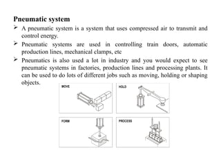
Pneumatic systems are used in controlling train doors, automatic
production lines, mechanical clamps, etc
Pneumatics is also used a lot in industry and you would expect to see
pneumatic systems in factories, production lines and processing plants. It
can be used to do lots of different jobs such as moving, holding or shaping
objects.
3.
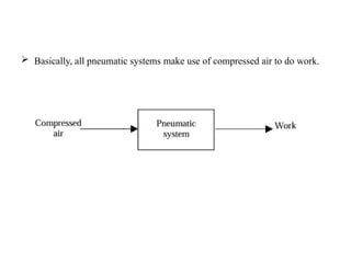
Basically, allpneumatic systems make use of compressed air to do work.
4.
The advantages ofpneumatic systems
High effectiveness: There is an unlimited supply of air in our atmosphere to produce
compressed air. Moreover, the use of compressed air is not restricted by distance, as it
can easily be transported through pipes. After use, compressed air can be released
directly into the atmosphere without the need of processing.
High durability and reliability: Pneumatic components are extremely durable and can
not be damaged easily.
Simple design: The designs of pneumatic components are relatively simple. They are
thus more suitable for use in simple automatic control systems.
High adaptability to harsh environment: Compared to the elements of other systems,
compressed air is less affected by high temperature, dust, corrosion, etc.
Safety: Pneumatic systems are safer than electromotive systems because they can work
in inflammable environment without causing fire or explosion. Unlike electromotive
components, pneumatic components do not burn or get overheated when overloaded.
Environmental friendly: The operation of pneumatic systems do not produce
pollutants.
Economical: As pneumatic components are not expensive, the costs of pneumatic
systems are quite low.
5.
Limitations of pneumaticsystems
Relatively low accuracy: As the volume of air may change when compressed or
heated, the supply of air to the system may not be accurate, causing a decrease in the
overall accuracy of the system.
Low loading: As the cylinders of pneumatic components are not very large, a pneumatic
system cannot drive loads that are too heavy.
Processing required before use: Compressed air must be processed before use to
ensure the absence of water vapour or dust. Otherwise, the moving parts of the
pneumatic components may wear out quickly due to friction.
Uneven moving speed: As air can easily be compressed, the moving speeds of the
pistons are relatively uneven.
Noise: Noise will be produced when compressed air is released from the pneumatic
components.
6.
pneumatic components
Pneumaticcomponents can be divided into two categories:
Components that produce and transport compressed air.
Components that consume compressed air.
7.
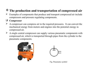
The productionand transportation of compressed air
Examples of components that produce and transport compressed air include
compressors and pressure regulating components.
Compressor
A compressor can compress air to the required pressures. It can convert the
mechanical energy from motors and engines into the potential energy in
compressed air.
A single central compressor can supply various pneumatic components with
compressed air, which is transported through pipes from the cylinder to the
pneumatic components.
Fig. Pneumatic symbol
8.
Pressure regulatingcomponent
Pressure regulating components are formed by various components, each
of which has its own pneumatic symbol:
i. Filter – can remove impurities from compressed air before it is fed to the
pneumatic components.
ii. Pressure regulator – to stabilise the pressure and regulate the operation
of pneumatic components
iii. Lubricator – To provide lubrication for pneumatic components
Fig. Pneumatic symbol
9.
The consumptionof compressed air
Examples of components that consume compressed air include
execution components (cylinders), directional control valves
and assistant valves.
Execution component
Pneumatic execution components provide rectilinear or rotary
movement.
Examples of pneumatic execution components include
cylinder pistons, pneumatic motors, etc.
Rectilinear motion is produced by cylinder pistons, while
pneumatic motors provide continuous rotations. There are
many kinds of cylinders, such as single acting cylinders and
double acting cylinders.
10.
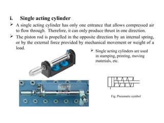
i. Single actingcylinder
A single acting cylinder has only one entrance that allows compressed air
to flow through. Therefore, it can only produce thrust in one direction.
The piston rod is propelled in the opposite direction by an internal spring,
or by the external force provided by mechanical movement or weight of a
load.
Fig. Pneumatic symbol
Single acting cylinders are used
in stamping, printing, moving
materials, etc.
11.
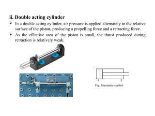
ii. Double actingcylinder
In a double acting cylinder, air pressure is applied alternately to the relative
surface of the piston, producing a propelling force and a retracting force.
As the effective area of the piston is small, the thrust produced during
retraction is relatively weak.
Fig. Pneumatic symbol
12.
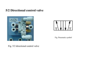
Directional controlvalve
Directional control valves ensure the flow of air between air
ports by opening, closing and switching their internal
connections.
Their classification is determined by the number of
ports/ways, the number of switching positions, the normal
position of the valve and its method of operation.
Common types of directional control valves include
2/2
3/2
5/2, etc.
The first number represents the number of ports; the second
number represents the number of positions.
13.
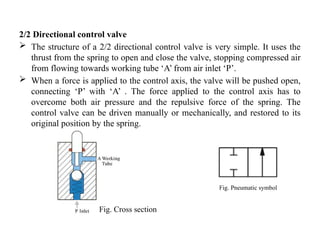
2/2 Directional controlvalve
The structure of a 2/2 directional control valve is very simple. It uses the
thrust from the spring to open and close the valve, stopping compressed air
from flowing towards working tube ‘A’ from air inlet ‘P’.
When a force is applied to the control axis, the valve will be pushed open,
connecting ‘P’ with ‘A’ . The force applied to the control axis has to
overcome both air pressure and the repulsive force of the spring. The
control valve can be driven manually or mechanically, and restored to its
original position by the spring.
Fig. Cross section
Fig. Pneumatic symbol
14.
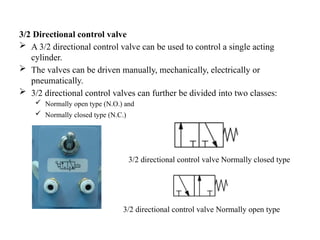
3/2 Directional controlvalve
A 3/2 directional control valve can be used to control a single acting
cylinder.
The valves can be driven manually, mechanically, electrically or
pneumatically.
3/2 directional control valves can further be divided into two classes:
Normally open type (N.O.) and
Normally closed type (N.C.)
3/2 directional control valve Normally closed type
3/2 directional control valve Normally open type
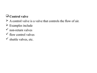
Control valve
A control valve is a valve that controls the flow of air.
Examples include
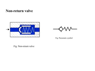
non-return valves
flow control valves
shuttle valves, etc.
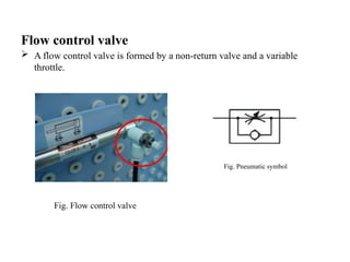
Flow control valve
A flow control valve is formed by a non-return valve and a variable
throttle.
Fig. Flow control valve
Fig. Pneumatic symbol
19.
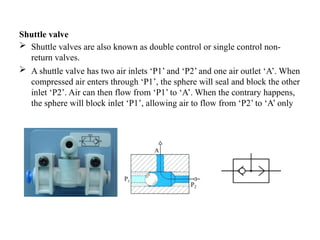
Shuttle valve
Shuttlevalves are also known as double control or single control non-
return valves.
A shuttle valve has two air inlets ‘P1’ and ‘P2’ and one air outlet ‘A’. When
compressed air enters through ‘P1’, the sphere will seal and block the other
inlet ‘P2’. Air can then flow from ‘P1’ to ‘A’. When the contrary happens,
the sphere will block inlet ‘P1’, allowing air to flow from ‘P2’ to ‘A’ only
20.
• All mainpneumatic components can be represented by simple pneumatic
symbols. Each symbol shows only the function of the component it
represents, but not its structure. Pneumatic symbols can be combined to
form pneumatic diagrams. A pneumatic diagram describes the relations
between each pneumatic component, that is, the design of the system.
21.
Pneumatic circuit diagram
A pneumatic circuit diagram uses pneumatic symbols to
describe its design. Some basic rules must be followed when
drawing pneumatic diagrams.