Download as PPSX, PPTX

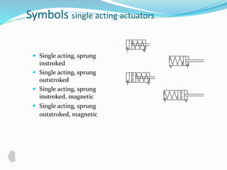
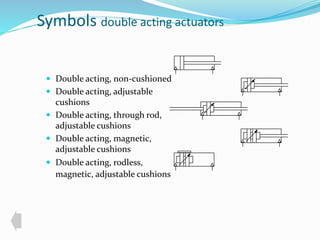
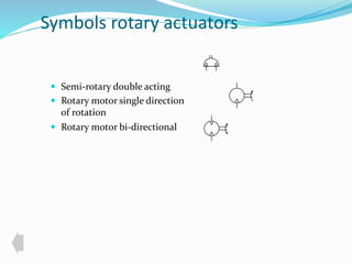
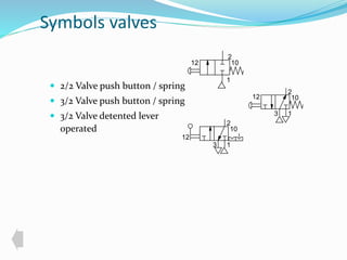
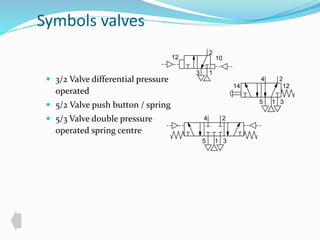
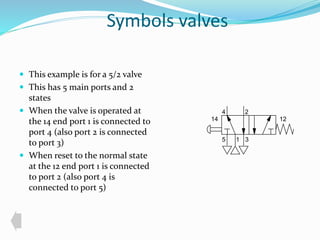
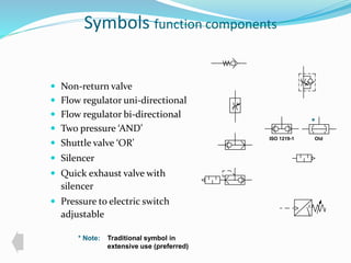
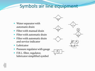
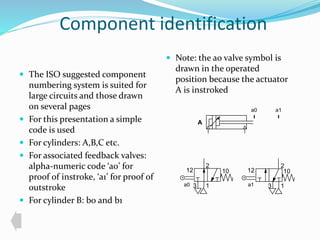
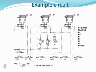
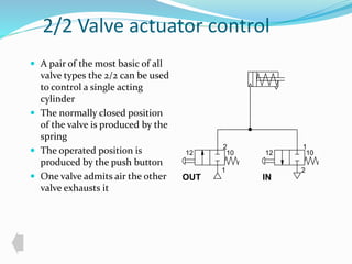
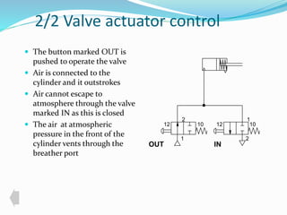
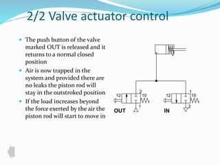
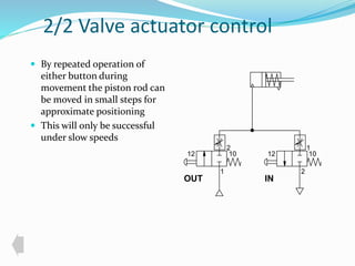
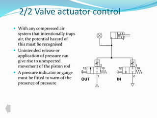


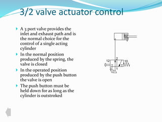
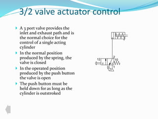
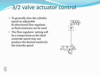
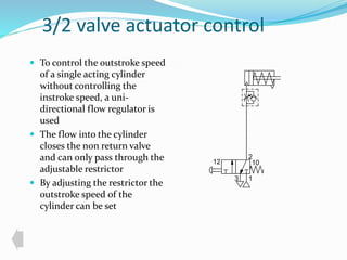
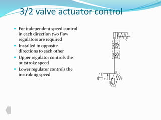
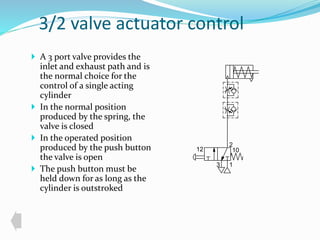

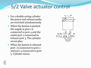
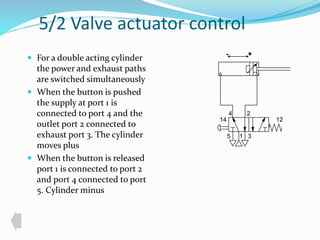
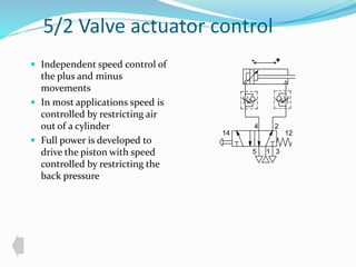
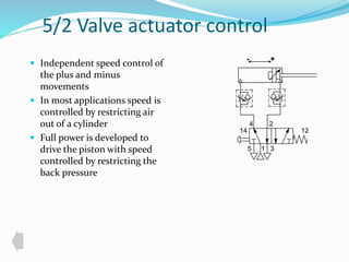
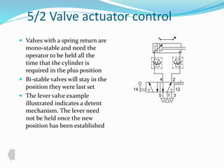
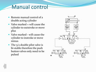
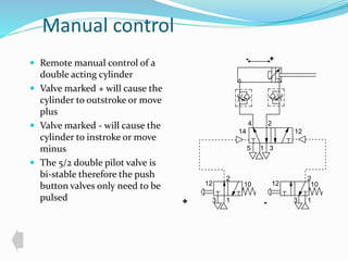
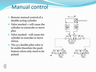
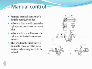

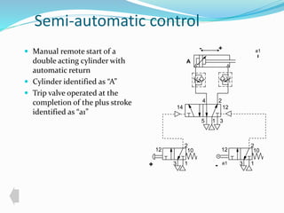
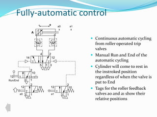

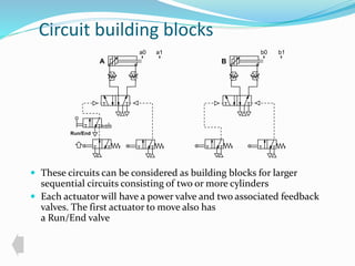
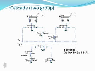
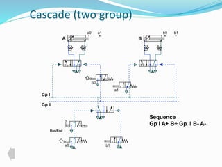
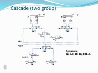
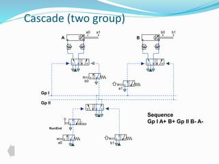
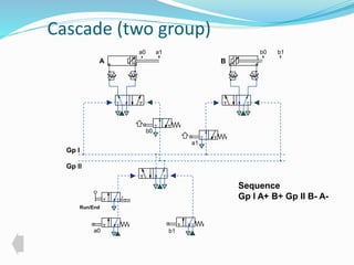

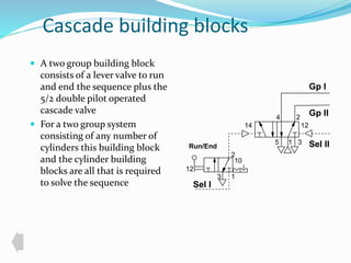
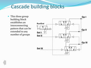
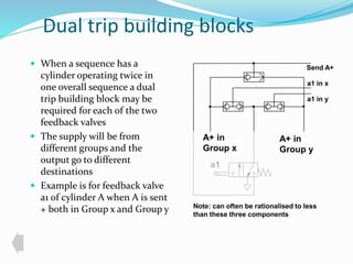

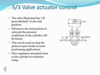


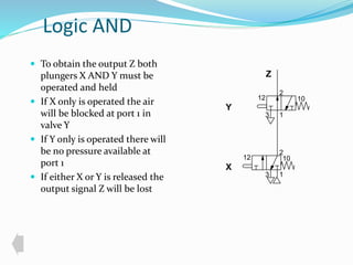


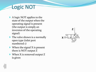
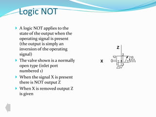

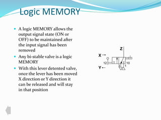
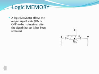
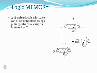
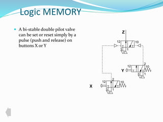
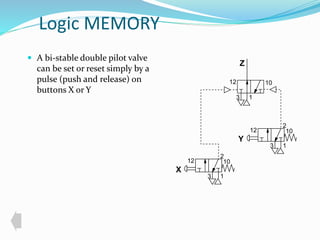
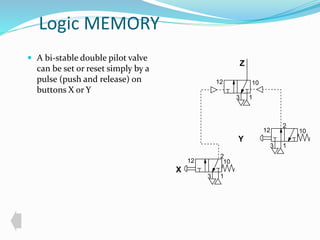

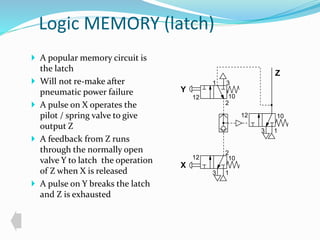
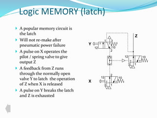
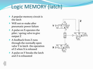
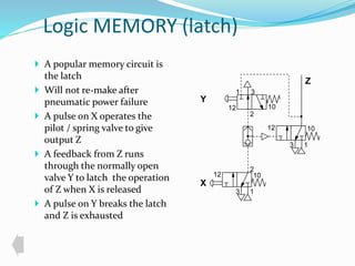

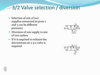
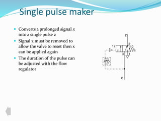
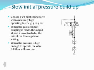
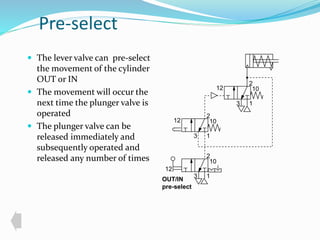
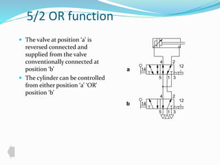
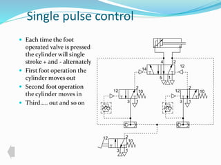
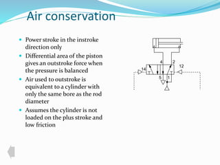
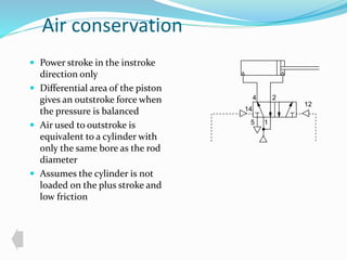
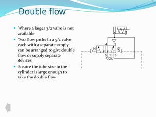
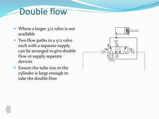

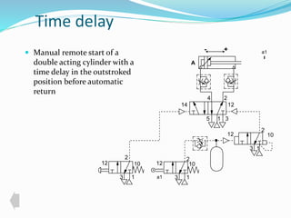

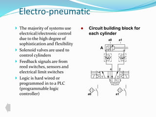


This document provides an overview of pneumatic control and automation concepts including: - Standard symbols for pneumatic components like cylinders, valves, and other devices based on ISO 1219 standards. - Examples of using 2/2 and 3/2 valves to control single-acting cylinders, and 5/2 valves to control double-acting cylinders. Speed control methods like flow regulators are discussed. - Sequential control concepts and examples of circuits using multiple cylinders operated in sequence are presented.


