Downloaded 120 times

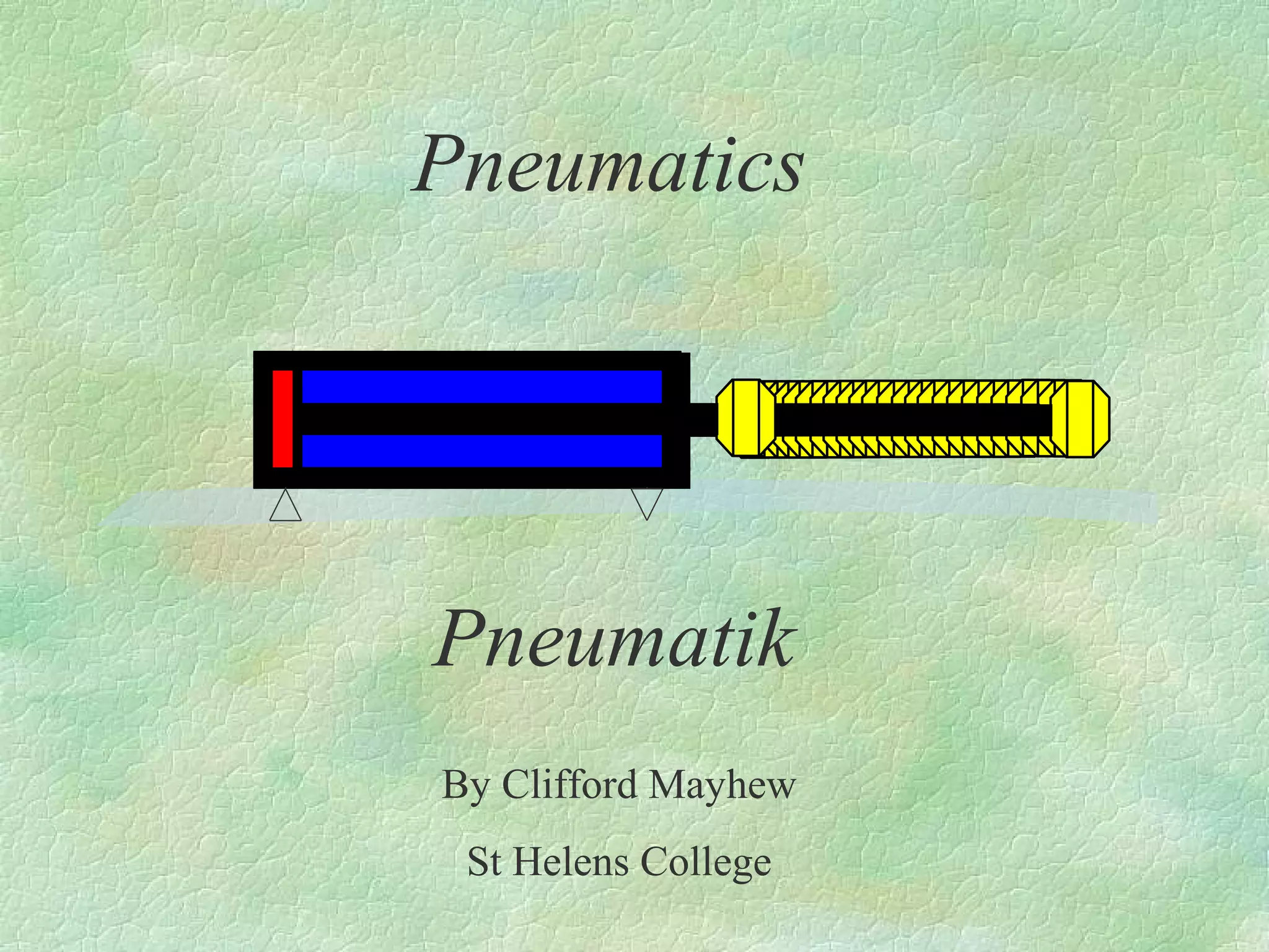

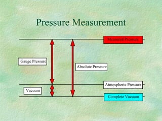
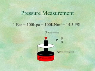
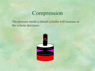
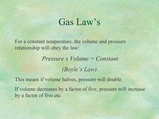
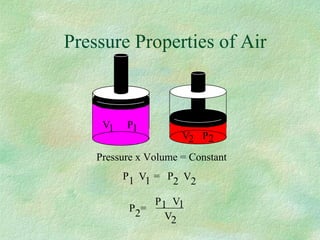
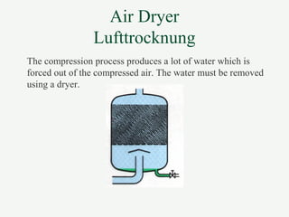
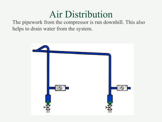
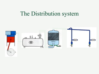
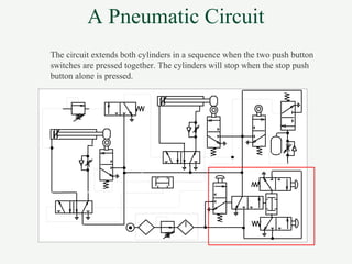
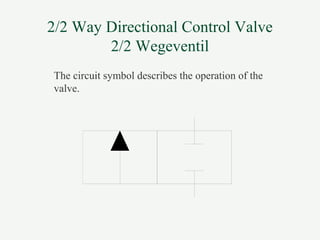
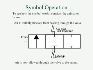
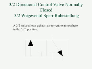
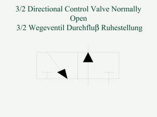

- Pneumatics uses compressed air to power machines and devices. It describes basic principles like pressure, measurements, and gas laws. - Compressed air is produced by compressors and stored in receivers with air dryers removing moisture. It is distributed through piping. - Common pneumatic components are valves, cylinders, filters, regulators, lubricators and other devices. Circuits use these components to control machine operations. - Symbols are used on drawings to represent pneumatic components and their functions in circuits. Valves direct air flow, cylinders provide linear motion, and other components condition and control the air.