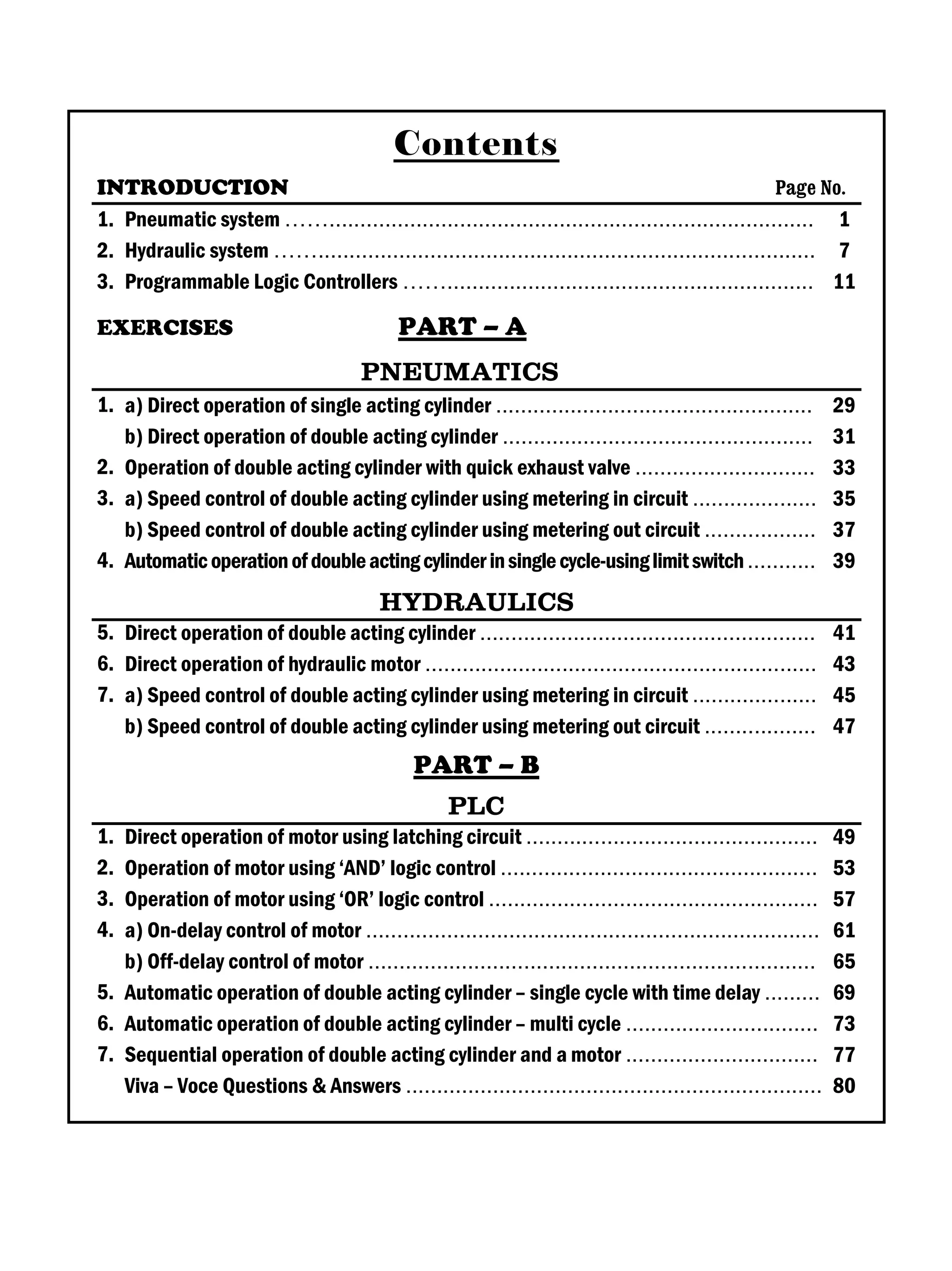
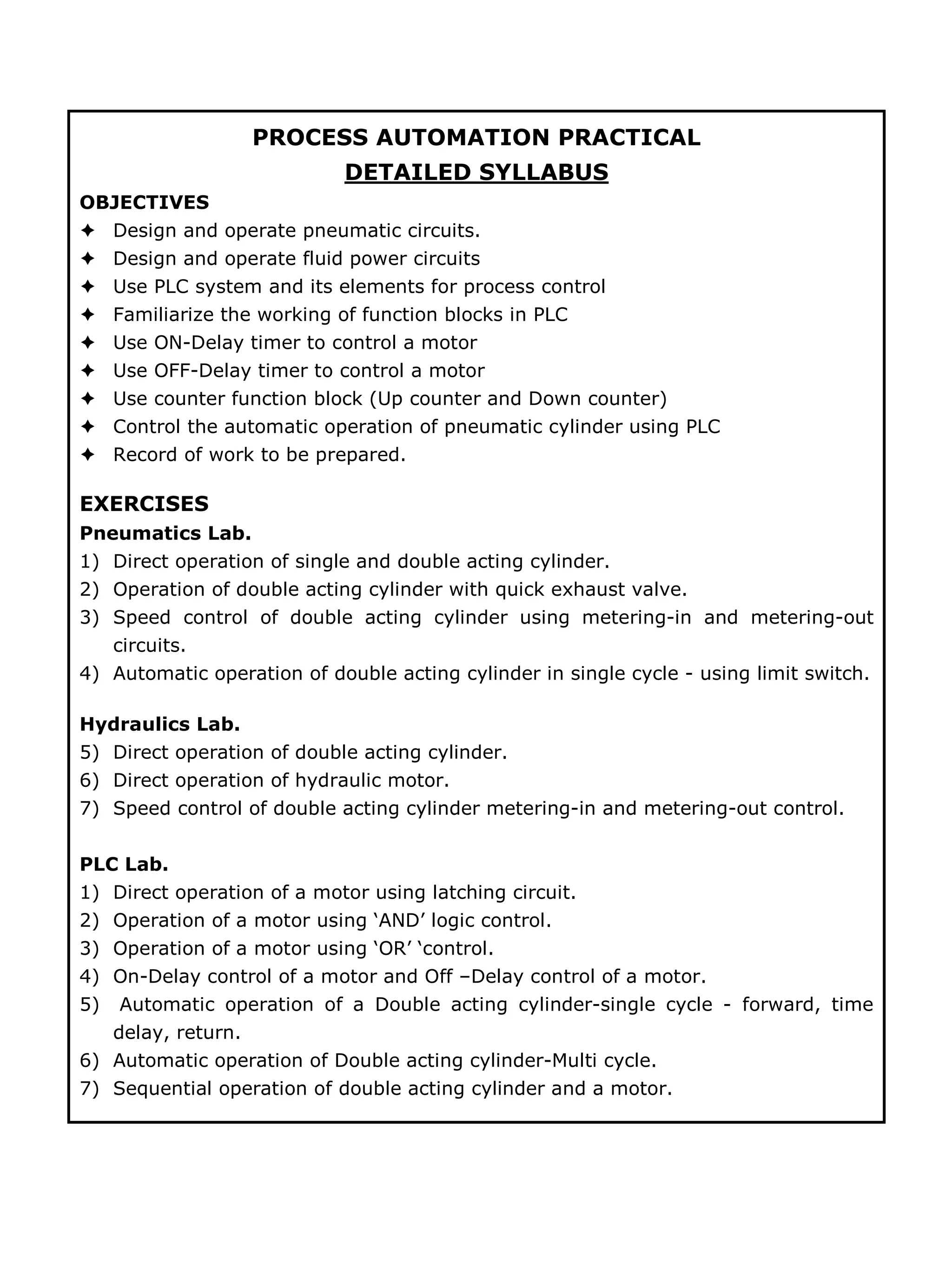
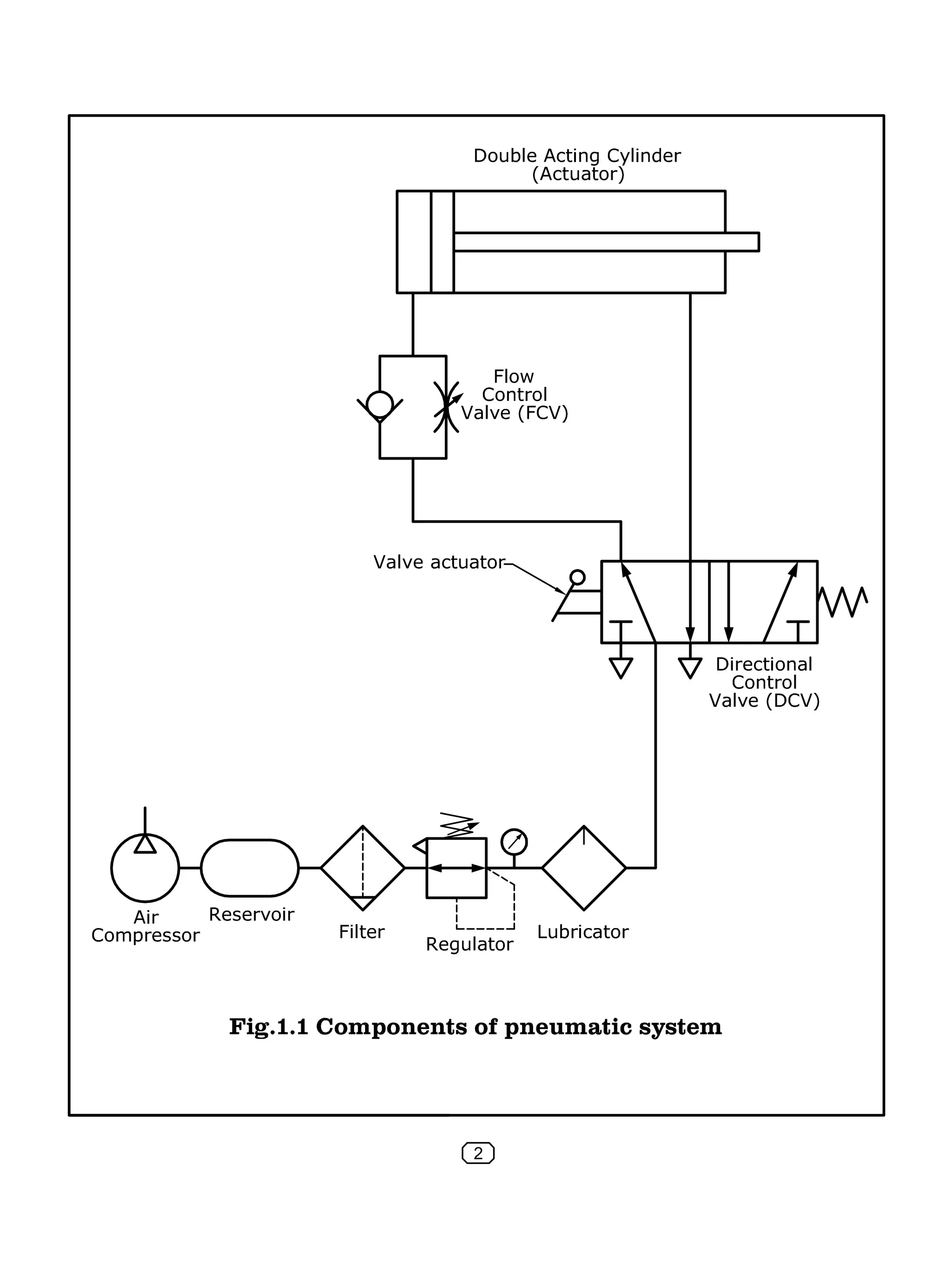
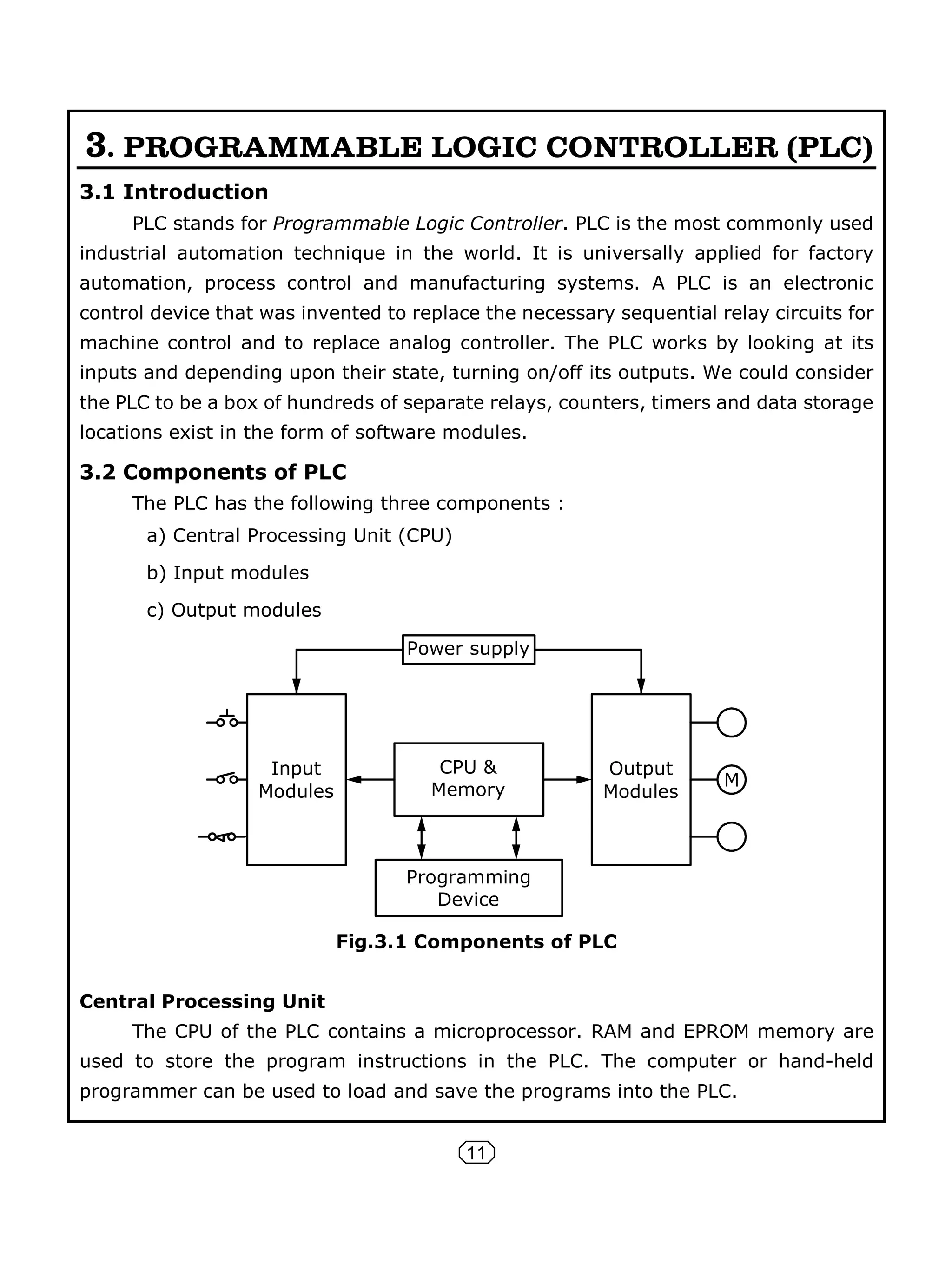
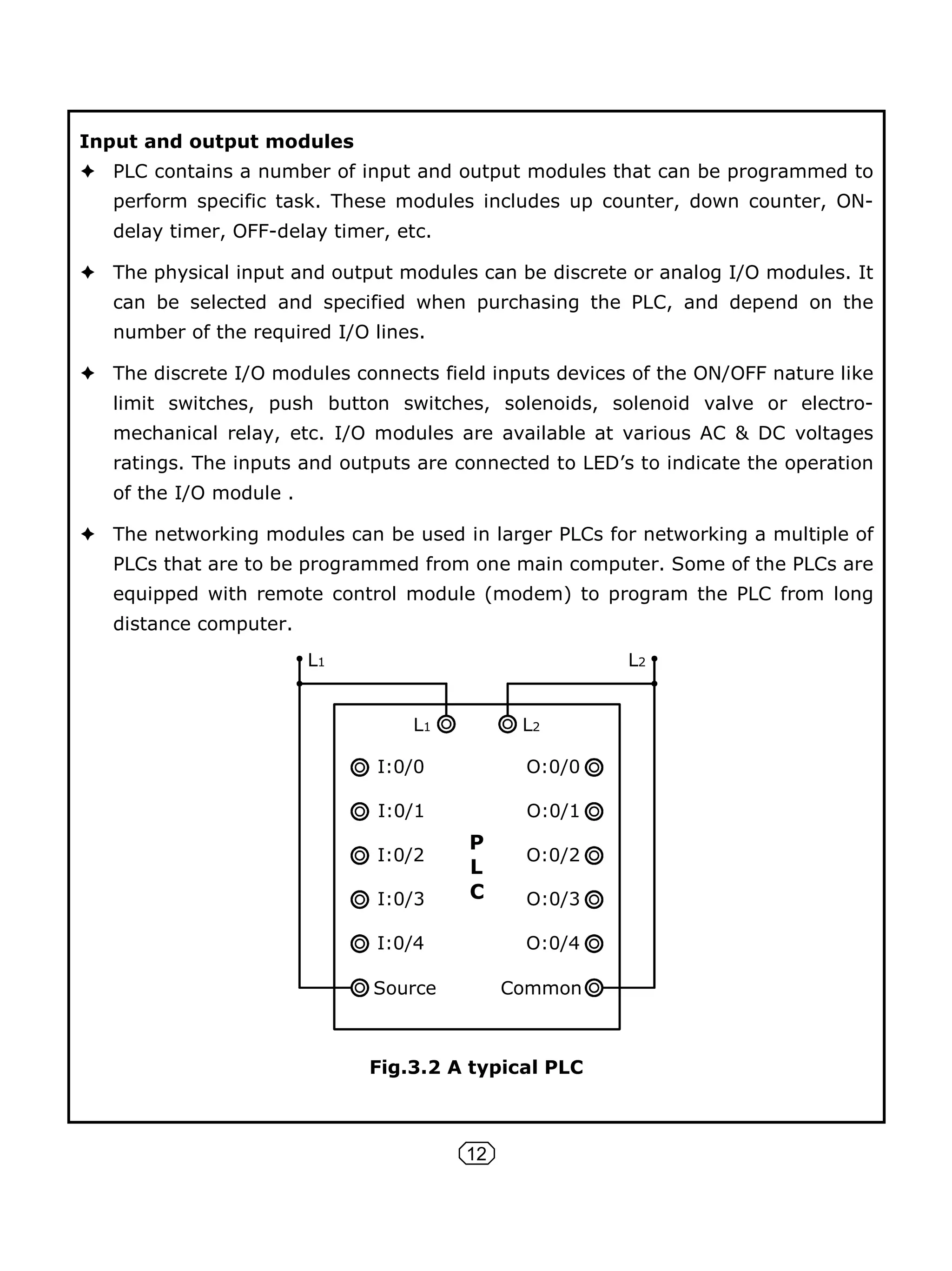
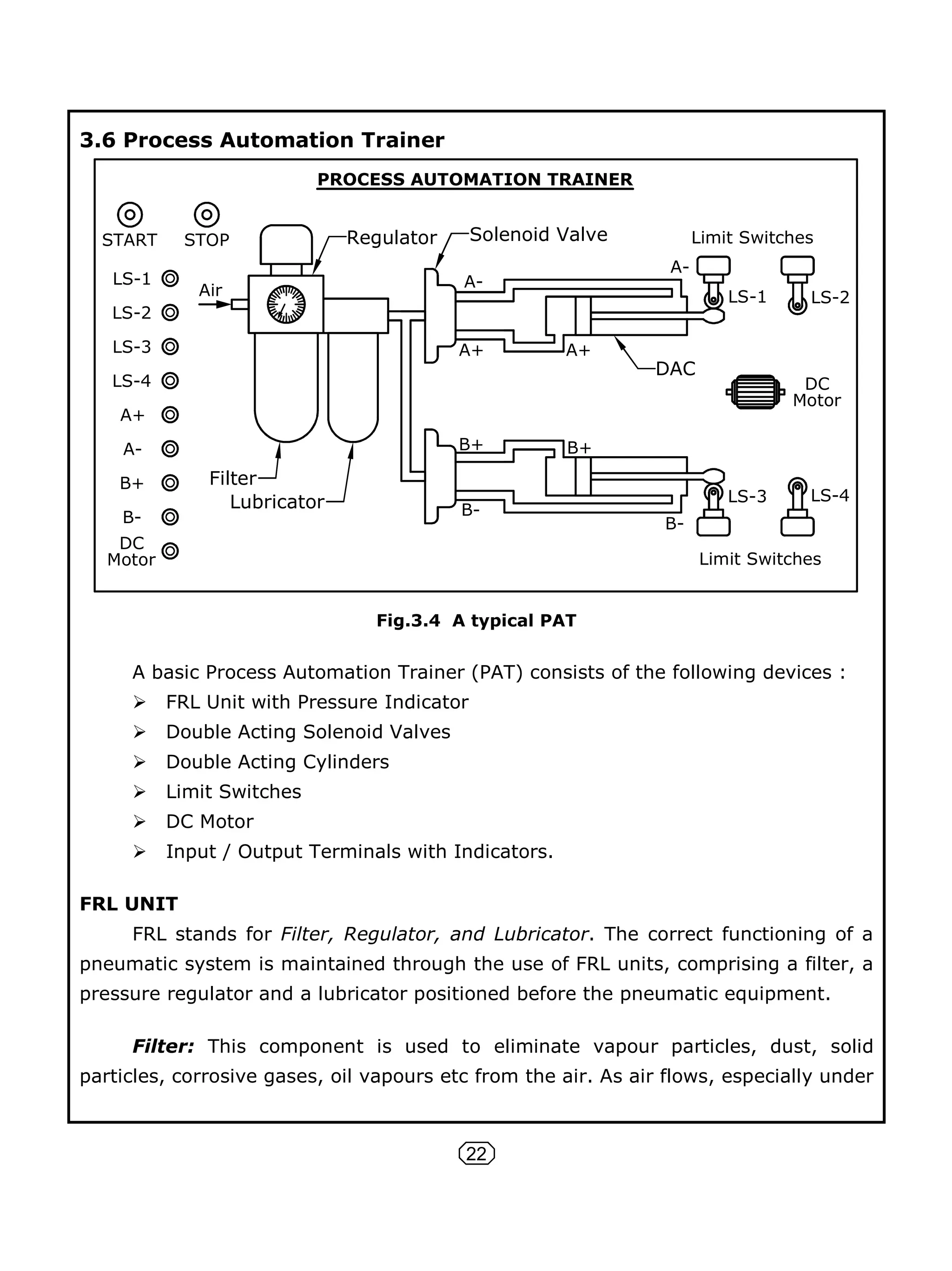
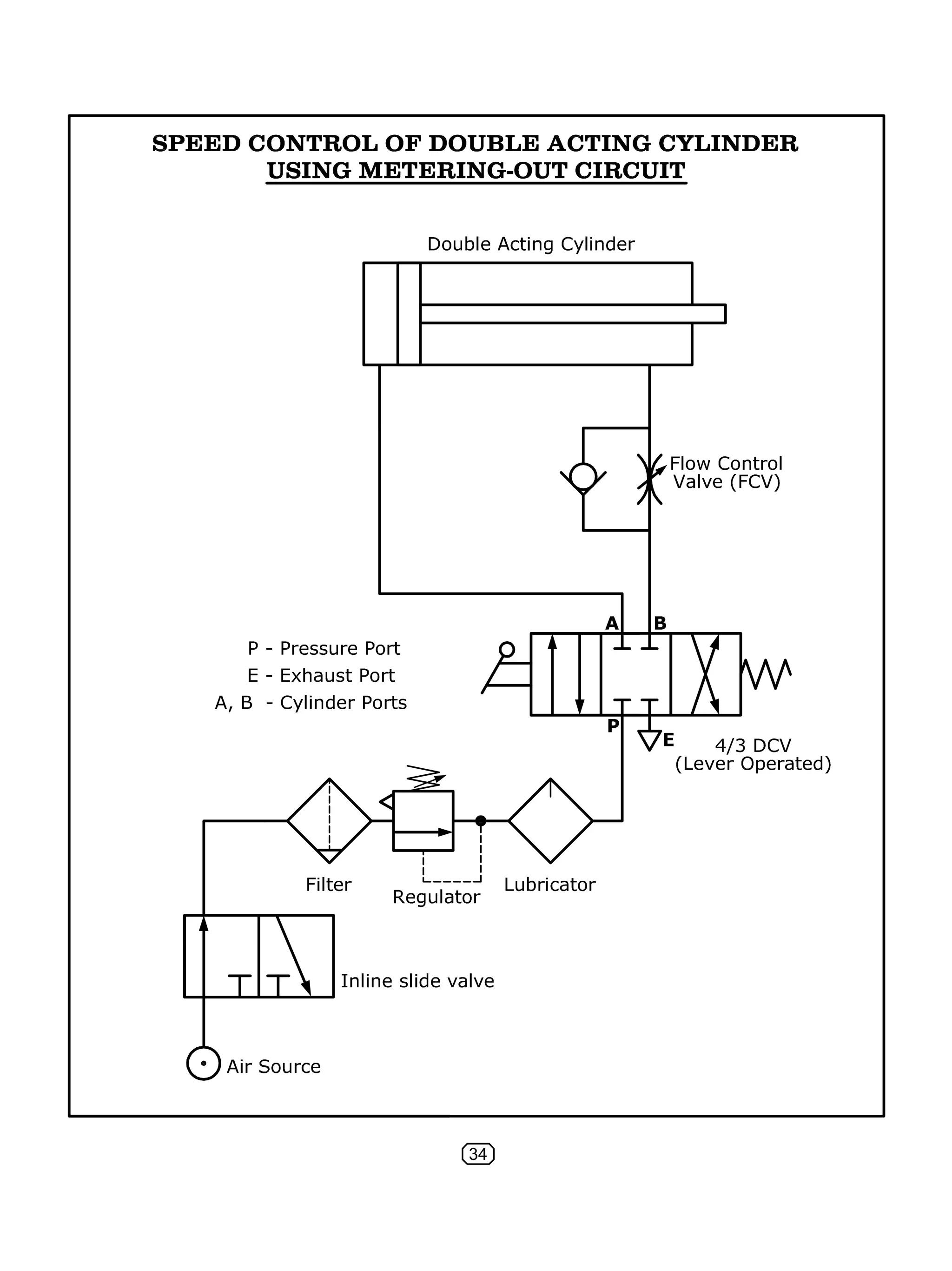
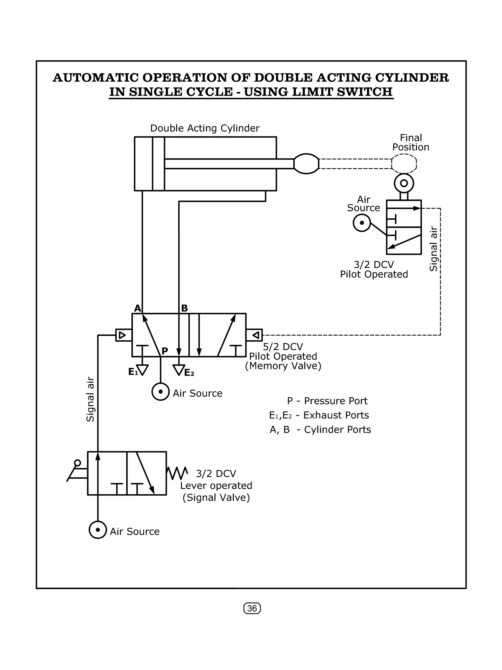
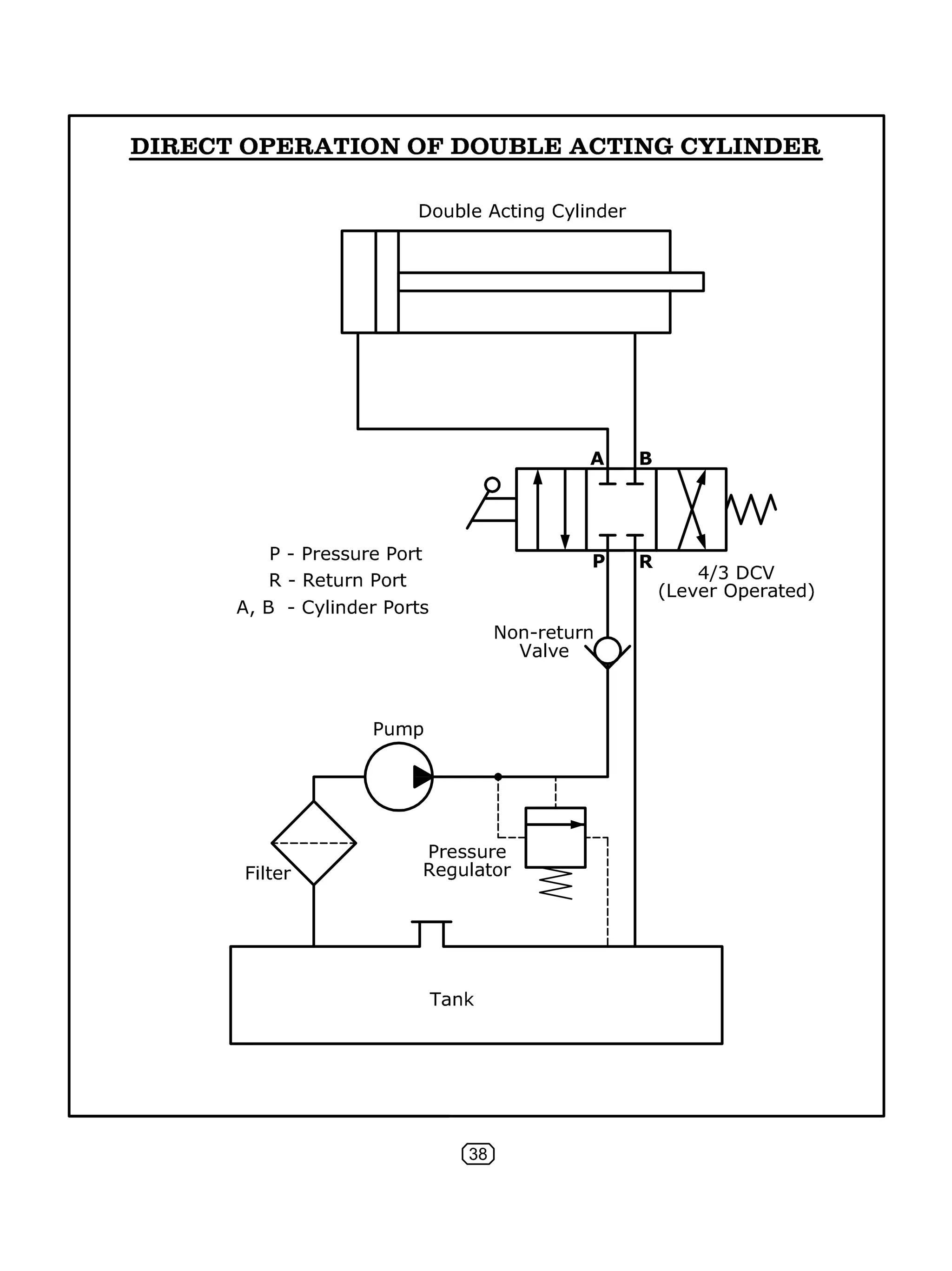
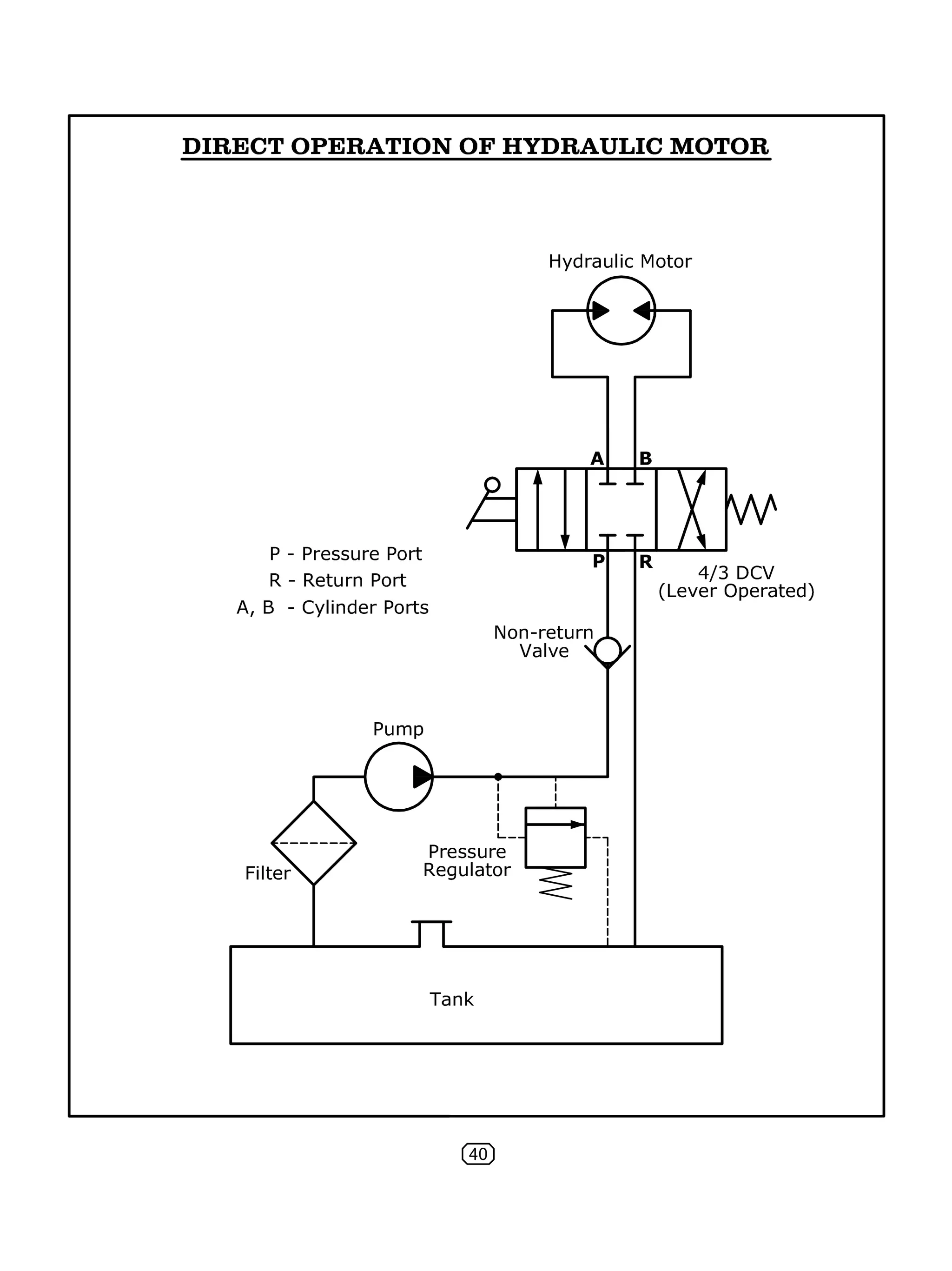
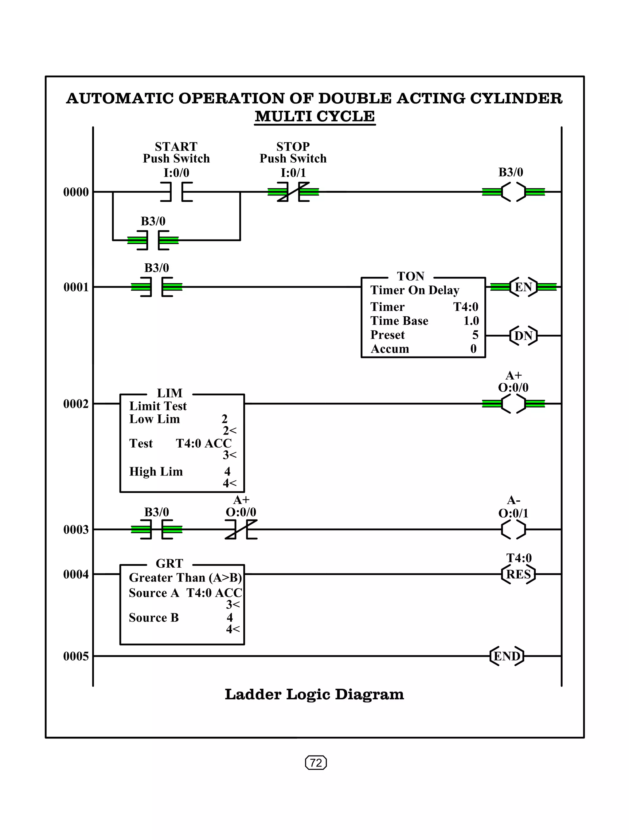
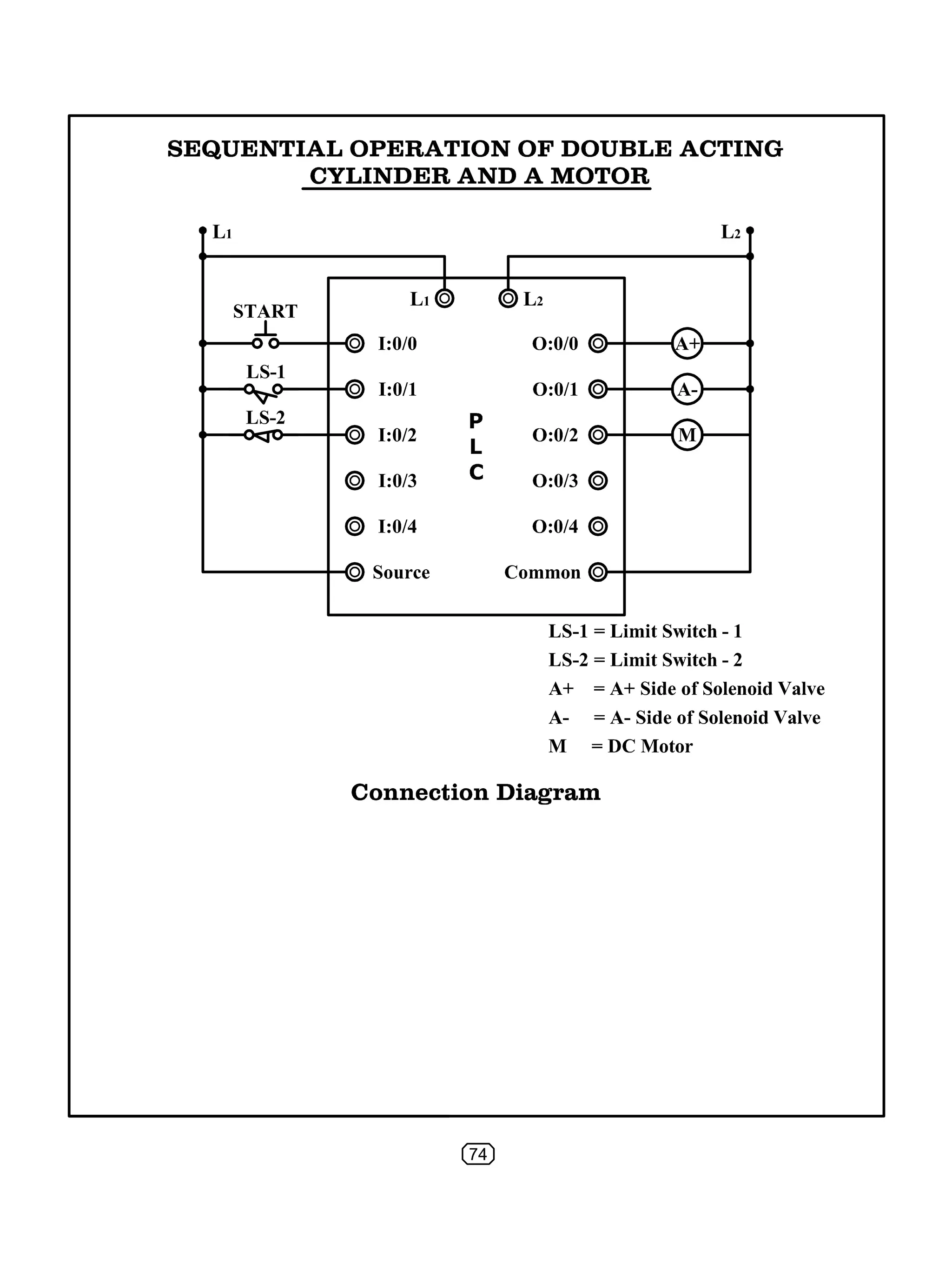
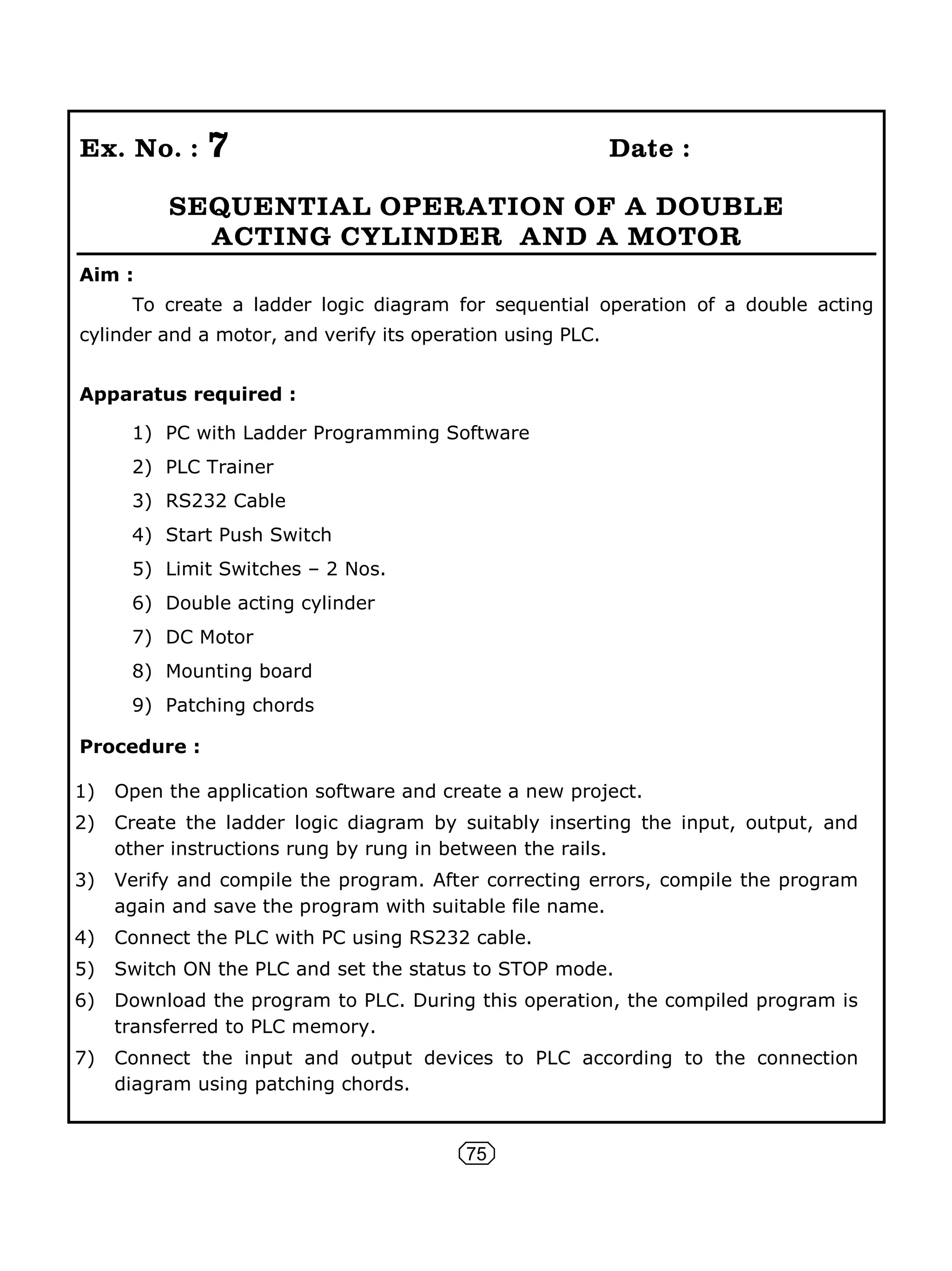
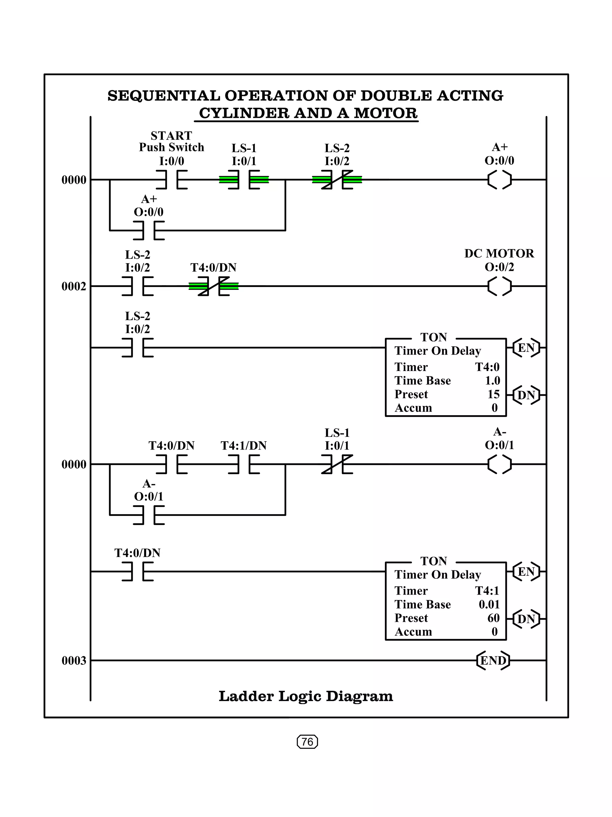
SlideShare a Scribd company logo
1 of 89
Download to read offline
PROCESS AUTOMATION
PRACTICAL MANUAL
(N – SCHEME)
N. IYANARAPPAN, M.E., M.I.S.T.E.
!
!
!
!
!
!
PROCESS AUTOMATION PRACTICAL MANUAL
Copy right © : KAL Pathippagam
No part of this publication may be stored in a retrieval system, transmitted or
reproduced in any way, including but not limited to photocopy, photograph, magnetic or
other record, without prior agreement and written permission of the publisher.
First Edition : June 2017
Revised Edition : August 2022
Price : 128.00
Publisher :
KAL PATHIPPAGAM
Vellore – 632 011
Type setting :
Students’ Media Computer Graphics
Vellore – 632 011.
For Contact :
99446 50380
96266 26747
Contents
INTRODUCTION Page No.
1. Pneumatic system …….............................................................................. 1
2. Hydraulic system ……................................................................................ 7
3. Programmable Logic Controllers ……........................................................... 11
EXERCISES PART – A
PNEUMATICS
1. a) Direct operation of single acting cylinder ................................................... 29
b) Direct operation of double acting cylinder .................................................. 31
2. Operation of double acting cylinder with quick exhaust valve ............................. 33
3. a) Speed control of double acting cylinder using metering in circuit .................... 35
b) Speed control of double acting cylinder using metering out circuit .................. 37
4. Automaticoperationofdoubleactingcylinderinsinglecycle-usinglimitswitch........... 39
HYDRAULICS
5. Direct operation of double acting cylinder ...................................................... 41
6. Direct operation of hydraulic motor ............................................................... 43
7. a) Speed control of double acting cylinder using metering in circuit .................... 45
b) Speed control of double acting cylinder using metering out circuit .................. 47
PART – B
PLC
1. Direct operation of motor using latching circuit ............................................... 49
2. Operation of motor using ‘AND’ logic control ................................................... 53
3. Operation of motor using ‘OR’ logic control ..................................................... 57
4. a) On-delay control of motor ......................................................................... 61
b) Off-delay control of motor ........................................................................ 65
5. Automatic operation of double acting cylinder – single cycle with time delay ......... 69
6. Automatic operation of double acting cylinder – multi cycle ............................... 73
7. Sequential operation of double acting cylinder and a motor ............................... 77
Viva – Voce Questions & Answers ................................................................... 80
PROCESS AUTOMATION PRACTICAL
DETAILED SYLLABUS
OBJECTIVES
Design and operate pneumatic circuits.
Design and operate fluid power circuits
Use PLC system and its elements for process control
Familiarize the working of function blocks in PLC
Use ON-Delay timer to control a motor
Use OFF-Delay timer to control a motor
Use counter function block (Up counter and Down counter)
Control the automatic operation of pneumatic cylinder using PLC
Record of work to be prepared.
EXERCISES
Pneumatics Lab.
1) Direct operation of single and double acting cylinder.
2) Operation of double acting cylinder with quick exhaust valve.
3) Speed control of double acting cylinder using metering-in and metering-out
circuits.
4) Automatic operation of double acting cylinder in single cycle - using limit switch.
Hydraulics Lab.
5) Direct operation of double acting cylinder.
6) Direct operation of hydraulic motor.
7) Speed control of double acting cylinder metering-in and metering-out control.
PLC Lab.
1) Direct operation of a motor using latching circuit.
2) Operation of a motor using ‘AND’ logic control.
3) Operation of a motor using ‘OR’ ‘control.
4) On-Delay control of a motor and Off –Delay control of a motor.
5) Automatic operation of a Double acting cylinder-single cycle - forward, time
delay, return.
6) Automatic operation of Double acting cylinder-Multi cycle.
7) Sequential operation of double acting cylinder and a motor.
1
1. PNEUMATIC SYSTEM
1.1 Introduction
A pneumatic system is a system that uses compressed air to transmit and
control energy. Pneumatic systems are used in many industrial applications such as:
Material handling
Clamping
Shifting
Positioning
Branching of material flow
Packaging
Filling
Transfer of materials
Sorting of parts
Stamping and embossing of components, etc.
Pneumatic systems are also used in carrying out machining and some industrial
processes such as:
Drilling
Turning
Milling
Sawing
Finishing
Forming, etc.
1.2 Components of pneumatic system
A simple pneumatic system consists of the following components :
1) Air compressor
2) Air reservoir
3) Air service unit (FRL unit)
4) Direction control valves
5) Control valves
6) Actuators
3
1) Air Compressor
Air compressor is used to produce the compressed air for the system by the
required volume and pressure. A single central compressor can supply various
pneumatic components with compressed air. Reciprocatory and rotary compressors
can be used.
2) Air reservoir (tank)
An air reservoir should be fitted to store and stabilizes the compressed air. It
also compensates the pressure fluctuation and cools the air.
3) Air service unit (FRL unit)
It consists of the following :
i) Filter : To remove impurities from compressed air before it is fed to the
pneumatic components.
ii) Pressure regulator: To stabilise the pressure and regulate the operation of
pneumatic components
iii) Lubricator : To provide lubrication for pneumatic components.
4)Directional control valves (DCV)
Directional control valves ensure the flow of air between air ports by opening,
closing and switching their internal connections. Their classification is determined by
the number of ports, the number of switching positions, the normal position of the
valve and its method of operation. Common types of directional control valves include
2/2, 3/2, 4/2, 4/3, 5/2, etc. The first number represents the number of ports; the
second number represents the number of positions.
i) 2/2 Directional Control Valve (2/2 DCV) : It has 2 ports and can be
operated with 2 positions, open and close. It uses the thrust force from the
spring to open and close the valve. When a force is applied the valve will be
pushed open. It connects the air inlet to the working tube.
ii) 3/2 Directional Control Valve (3/2 DCV) : It has 3 ports and can be
operated in 2 positions. This valve can be used to control a single acting
cylinder. When the spool of a three-way valve is in one extreme position, the
pressure passage is connected with the actuator passage. When in the other
4
extreme position, the spool connects the actuator passage with the exhaust
passage. The valves can be driven manually, mechanically, electrically or
pneumatically. 3/2 directional control valves can be Normally open type (NO)
or Normally closed type (NC)
iii) 4/2 Directional Control Valve (4/2 DCV) : It has 4 ports and can be
operated in 2 positions. A common application of four-ported four-way
directional valve is to cause reversible motion of a cylinder or motor. To perform
this function, spool connects the pressure port with one actuator port. At the
same time, the spool connects the other actuator port with the exhaust port.
iv) 4/3 Directional Control Valve (4/3 DCV) : It has 4 ports and can be
operated in 3 positions. The ports include one pressure port, two actuator
ports, and one exhaust ports. When it is operated in the left and right position,
spool connects the pressure port with one actuator port. At the same time, the
spool connects the other actuator port with the exhaust port. In the middle
position, it disconnects all the inlet and outlet ports.
v) 5/2 Directional Control Valve (5/2 DCV) : It has 5 ports and can be
operated in 2 positions. The ports include one pressure port, two actuator
ports, and two exhaust ports. Such valves provide the same basic control of
flow paths as the four-ported version, but have individual exhaust ports. Each
exhaust port serves an actuator port. This directional valve will remain in
operational position until another signal is received. Therefore, this type of
DCV is known as ‘memory valve’.
5) Control valves
A control valve is a valve that controls the flow of air. Examples include non-
return valves, flow control valves, shuttle valves, etc.
i) Non-return valve : A non-return valve allows air to flow in one direction only.
When air flows in the opposite direction, the valve will close. Another name
for non-return valve is poppet valve or check valve.
ii) Flow control valve : A flow control valve is formed by a non-return valve and
a variable throttle.
5
iii) Shuttle valve : It is also known as double control or single control non-return
valve. A shuttle valve has two air inlets and one air outlet. When compressed
air enters through one inlet port, the sphere inside the valve passage will seal
and block the other inlet port. Air can then flow from one inlet port to outlet.
iv) Quick exhaust valve : It is used for the quick exhaust of air to cause rapid
forward or return movement of actuator.
6) Actuators
Pneumatic actuator components provide rectilinear or rotary movement.
Examples include cylinder pistons, pneumatic motors, etc.
i) Single acting cylinder : It has only one entrance that allows compressed air
to flow through. Therefore, it can only produce thrust in one direction The
piston rod is propelled in the opposite direction by an internal spring, or by the
external force provided by mechanical movement or weight of a load.
ii) Double acting cylinder : In a double acting cylinder, air pressure is applied
alternatively to both the side of the piston, producing a propelling force and a
retracting force.
iii) Pneumatic motors : Motors with one direction or two direction rotation are
available. In a two direction rotation motors, air pressure is applied alternately
to both the side, producing a rotary movement.
Valve actuators
The directional control valves can be operated using a number of actuating
mechanisms. The following are the important valve actuators :
Manual
Spring Push button Lever
Mechanical Solenoid Air pilot
6
1.3 ISO symbols of pneumatic components
Symbol Description Symbol Description
Air source Flow direction
External port not
connected
Exhaust to atmosphere
Air compressor Air reservoir
Air dryer FRL unit
Air filter Regulator
Lubricator 2/2 DCV
3/2 DCV – Normally Closed
(Inline slide valve)
3/2 DCV – Normally Open
4/2 DCV
5/2 DCV
(Memory Valve)
Non return valve
(Check valve)
Flow Control valve
Shuttle valve Quick exhaust valve
Fixed restriction Adjustable restriction
Single acting cylinder Double acting cylinder
Pneumatic motor
(One direction & Two
direction)
7
2. HYDRAULIC SYSTEM
2.1 Introduction
An hydraulic system is an enclosed fluid based system that uses pressurized
incompressible liquids to transmit and control energy. The hydraulic system works
on the principle of Pascal’s law which says that the pressure in an enclosed fluid is
uniform in all the directions.
The hydraulic systems are mainly used for precise control of larger forces. The
main applications of hydraulic system include the following :
Industrial : Plastic processing machineries, steel making and primary metal
extraction applications, automated production lines, machine tool industries,
paper industries, loaders, crushes, textile machineries, R & D equipment and
robotic systems etc.
Mobile hydraulics : Tractors, irrigation system, earthmoving equipment,
material handling equipment, commercial vehicles, tunnel boring equipment,
rail equipment, building and construction machineries and drilling rigs etc.
Automobiles : It is used in the systems like breaks, shock absorbers, steering
system, wind shield, lift and cleaning etc.
Marine applications : It mostly covers ocean going vessels, fishing boats
and navel equipment.
Aerospace equipment : There are equipment and systems used for rudder
control, landing gear, breaks, flight control and transmission etc. which are
used in airplanes, rockets and spaceships.
2.2 Components of hydraulic system
The hydraulic system is also called as hydraulic power pack or power unit. It
consists of the following components :
1) Storage tank
2) Filter
3) Pump
4) Pressure regulator
5) Control valves
6) Actuator
9
1) Storage tank
The storage tank is a reservoir for the liquid used as a transmission media.
The liquid used is generally high density incompressible oil.
2) Filter
Filter removes dust or any other unwanted particles from the oil before it is
pumped to pipeline. It helps to keep the fluid system clean and efficient, as well as
avoid damage to the actuator and valves.
3) Pump
The hydraulic pump converts mechanical energy into hydraulic energy by
moving, or transmitting, the hydraulic fluid. The capacity of pump depends on the
hydraulic system design. These pumps generally deliver constant volume in each
revolution of the pump shaft. There are several types of hydraulic pumps including
gear, vane and piston pump.
4) Pressure regulator
Pressure regulators maintain the required level of pressure in the hydraulic
fluid by redirecting the excess fluid back to the storage tank.
5) Control valves
Valves are used to control the direction, pressure and flow rate of a fluid
flowing through the circuit.
Directional Control Valves : These valves are used to control the start, stop
and change in direction of the fluid flow. Examples include check valve, 2/2 DCV,
3/2 DCV, 4/2 DCV, 5/2 DCV, etc.
Flow Control Valves : A flow control valve can regulate the flow or pressure of
the fluid. The fluid flow is controlled by varying area of the valve opening through
which fluid passes. Examples include glove valve, butterfly valve, ball valve,
balanced valve, etc.
Pressure relief valves : The pressure relief valves are used to protect the
hydraulic components from excessive pressure. This is one of the most important
components of a hydraulic system and is essentially required for safe operation
of the system. Examples include direct relief valve, unloading valve, sequence
valve, counterbalance valve, pressure reducing valve, etc.
10
6) Actuator
The hydraulic actuator is a device used to convert the fluid power into
mechanical power to do useful work. The actuator may be of the linear type (hydraulic
cylinder) or rotary type(hydraulic motor) to provide linear or rotary motion
respectively.
The leak proof piping is also important due to safety, environmental hazards
and economical aspects. Some accessories such as flow control system, travel limit
control, electric motor starter and overload protection may also be used in the
hydraulic systems.
11
3. PROGRAMMABLE LOGIC CONTROLLER (PLC)
3.1 Introduction
PLC stands for Programmable Logic Controller. PLC is the most commonly used
industrial automation technique in the world. It is universally applied for factory
automation, process control and manufacturing systems. A PLC is an electronic
control device that was invented to replace the necessary sequential relay circuits for
machine control and to replace analog controller. The PLC works by looking at its
inputs and depending upon their state, turning on/off its outputs. We could consider
the PLC to be a box of hundreds of separate relays, counters, timers and data storage
locations exist in the form of software modules.
3.2 Components of PLC
The PLC has the following three components :
a) Central Processing Unit (CPU)
b) Input modules
c) Output modules
Fig.3.1 Components of PLC
Central Processing Unit
The CPU of the PLC contains a microprocessor. RAM and EPROM memory are
used to store the program instructions in the PLC. The computer or hand-held
programmer can be used to load and save the programs into the PLC.
M
Output
Modules
CPU &
Memory
Input
Modules
Power supply
Programming
Device
12
Input and output modules
PLC contains a number of input and output modules that can be programmed to
perform specific task. These modules includes up counter, down counter, ON-
delay timer, OFF-delay timer, etc.
The physical input and output modules can be discrete or analog I/O modules. It
can be selected and specified when purchasing the PLC, and depend on the
number of the required I/O lines.
The discrete I/O modules connects field inputs devices of the ON/OFF nature like
limit switches, push button switches, solenoids, solenoid valve or electro-
mechanical relay, etc. I/O modules are available at various AC & DC voltages
ratings. The inputs and outputs are connected to LED’s to indicate the operation
of the I/O module .
The networking modules can be used in larger PLCs for networking a multiple of
PLCs that are to be programmed from one main computer. Some of the PLCs are
equipped with remote control module (modem) to program the PLC from long
distance computer.
Fig.3.2 A typical PLC
I:0/0
L2
O:0/0
I:0/1 O:0/1
I:0/2 O:0/2
I:0/3 O:0/3
I:0/4 O:0/4
Source Common
L2
P
L
C
L1
L1
13
Advantages of PLC
 Flexibility: One single Programmable Logic Controller can easily run many
machines.
 Correcting Errors: With PLC control any change in circuit design or sequence is
as simple as retyping the logic. Correcting errors in PLC is extremely short and
cost effective.
 Space Efficient: Today's Programmable Logic Control memory is getting bigger
and bigger this means that we can generate more and more contacts, coils,
timers, sequencers, counters and so on. We can have thousands of contact timers
and counters in a single PLC.
 Low Cost: Prices of Programmable Logic Controllers vary from few hundreds to
few thousands.
 Testing: A Programmable Logic Control program can be tested and evaluated in a
lab. The program can be tested, validated and corrected saving very valuable time.
 Visual observation: When running a PLC program a visual operation can be seen
on the screen. Hence troubleshooting a circuit is really quick, easy and simple.
3.3 PLC programing languages
IEC 1131-3 is the international standard for PLC programming languages. One
of the primary benefits of the standard is that it allows multiple languages to be used
within the same programmable controller. This allows the program developer to
select the language best suited to each particular task.
The following is a list of programming languages specified by this standard:
1) Ladder Logic Diagram (LD)
2) Function Block Diagram (FBD)
3) Sequential Function Charts (SFC)
4) Structured Text (ST)
14
1) Ladder Logic Diagram (LLD)
Ladder Logic Diagram is best used for
 Boolean operations
 Complex logical operations
 Message and communication processing
 Interlocks
 Troubleshoot a machine or process
2) Function Block Diagram (FBD)
Function Block Diagram is a graphical language. In FBD, program elements
appear as blocks, which are connected together with lines that represent wires in a
way, that look much like a circuit diagram. Function Block Diagram is best used for:
 Drive control
 Loop control
 Calculation in fluid control
3) Sequential Function Chart (SFC)
Sequential Function Chart is a graphical language used to organize the flow and
control of complex, simultaneous operations. It graphically shows the state and the
transition used in a process. SFC is best used for:
 Simultaneous operations
 Repetitive sequences of operations
 Batch process
 Motion control
 State machine
4) Structured Text (ST)
Structured Text is a high-level language that resembles to Pascal or Basic.
Programmers trained in those languages often is very easy to learn. ST allows easy
modeling and performs loops and conditional branching. ST is best used for:
 Complex mathematical operations
 Array and table processing
 ASCII string handling
15
3.4 Ladder Logic Diagram
A very commonly used method of programming PLCs is based on the use of
ladder logic diagrams. Writing a program is then equivalent to drawing a switching
circuit. The ladder diagram consists of two vertical lines representing the power rails.
Circuits are connected as horizontal lines, i.e., the rungs of the ladder, between these
two verticals.
Conventions used in ladder diagrams :
1) The vertical lines of the diagram represent the power rails between which
circuits are connected. The power flow is taken to be from the left-hand
vertical across a rung.
2) Each rung on the ladder defines one operation in the control process.
3) A ladder diagram is read from left to right and from top to bottom.
4) The end rung might be indicated by a block with the word END or RET for
return.
5) Each rung must start with an input and end with at least one output.
6) Electrical devices are shown in their normal condition. A switch that is
normally closed is shown closed.
7) A particular device can appear in more than one rung of a ladder. The same
letters and/or numbers are used to label the device in each situation.
8) The inputs and outputs are all identified by their addresses, the notation used
depending on the PLC manufacturer. This is the address of the input or output
in the memory of the PLC.
Ladder Logic Instructions
Ladder logic instructions are commands which use inputs and counter relays to
determine the status of outputs and other counter relays. The basic instructions used
in ladder logic programming are are tabulated below.
16
Instruction Symbol Description
XIC
(eXamine If
Close)
Normally open contact. Passes power if a bit
is on.
XIO
(eXamine If
Open)
Normally closed contact. Passes power if a
bit is off .
OTE
(OuTput
Energize)
Output or coil. If any left-to-right rung path
passes power, a bit is energized.
OTL
(OuTput
Latch)
Latch coil. If any rung path passes power,
output is energized and remains energized,
even when no rung path passes power.
OTU
(OuTput
Unlatch)
Unlatch coil. If any rung path passes power,
output is de-energized and remains de-
energized, even when no rung path passes
power.
CTU
(CounT Up)
CTU counts false to true transition. When
this transition happens the accumulated
value is incremented by one count.
CTD
(CounT
Down)
CTD counts false to true transition. When
this transition happen the accumulated
value is decrements by one count.
RES
(RESet)
Resets the accumulated value and status bit
of a timer or counter.
TON
(Timer On
Delay)
It counts time base intervals when rung
conditions become true. As long as rung
conditions remain true, the timer adjust its
accumulated value (ACC) each evaluation
until it reaches the preset value (PRE). The
accumulated value is reset when rung
conditions go false.
I:0/0
I:0/1
O:0/1
B:0/1
L
B:0/2
U
CTU
Count Up
Counter C3:0
Preset 10
Accum 0
EN
DN
CTD
Count Down
Counter C4:0
Preset 10
Accum 0
EN
DN
RES
C3:0
TON
Timer On Delay
EN
DN
Timer T4:1
Time Base 1.0
Preset 10
Accum 0
17
Instruction Symbol Description
TOF
(Timer Off
Delay)
It counts time base intervals when the rung
makes a true to false transition. As long as
rung conditions remain false, the timer
increments its accumulated value (ACC)
each scans until it reaches the preset value
(PRE). The accumulated value is reset when
rung conditions go true.
RTO
(ReTentive
Timer On)
Counts time base intervals when the
instruction is true and retains the
accumulated value when the instruction
goes false or when power cycle occurs.
Math instruction
Instruction Description
ADD Add two values
SUB Subtract two values
MUL Multiply one value from another
DIV Divide one value by another
DDV Perform a double divide
NEG Change the sign of the source value
and place it in the destination
CLR Set all bits of a world to zero
TOD Convert an integer to BCD
FRD Convert a BCD value to an integer value
DCD Multiplex data
SQR Find the square roof of a value
SCL Scale a value
TOF
Timer Off Delay
EN
DN
Timer T2:1
Time Base 1.0
Preset 10
Accum 0
RTO
Retentive Timer ON
EN
DN
Timer T4:1
Time Base 1.0
Preset 10
Accum 0
18
Comparison Instructions
Instruction Description
EQU Test whether two value is not equal
EQ Test whether one value is not equal to
LES Test whether one value is less than a second value
LEQ Test whether one value is less than or equal to a second value
GRT Test whether one equal to second value is greater than another
GEQ Test whether one value is greater than or equal to a second value
MEQ Test portions of two values to see whether they are equal
LIM Test whether one value is within the limit range of two other values
Move and Logical Instructions
Instruction Description
MOV Move the source value to the destination
MVM Move data from a source location to a selected portion of the
destination
AND Perform an AND operation
OR Perform an inclusive OR operation
XOR Perform an Exclusive Or operation
NOT Perform a NOT operation
19
3.5 PLC Programming software
The following is the list of softwares used for PLC Programming.
Manufacturer Name of Software Supported PLCs
Rockwell Automation
(Allen-Bradley)
RSLogix 5000 CompactLogix and ControlLogix PLCs
RSLogix Micro MicroLogix 1000 or 1100 PLCs
Siemens Step 7 S7-300, S7-400 and S7-1200 PLCs
Divelbiss EZ Ladder All Divelbiss PLCs
Schneider TwidoSuite Twido PLCs
Mitsubishi
AL-PCS/WIN Alpha 2 Programmable Relay
GX Developer MELSEC QnA/QnAS/System FX PLCs
iQ Works Q, F and L Series PLCs.
Velocio vBuilder Ace and Branch PLCs
Panasonic FPWIN PRO All FP series PLCs
Keyence KV Ladder Builder KV and KV-300 PLCs
Telemecanique Zelio Soft Zelio Programmable Relays
GE Durus Durus Programmable Relays
Automation Direct Do More Do More PLC
IDEC WindLDR Microsmart Pentra PLCs
Omron CX One CJ, CP, CPM, CQM and CS PLCs
Sirea μLadder μArm A1-A10
VIPA VIPA All VIPA model PLCs
Triangle Research TRiLOGI Nano-10, F, E, H and M-series PLCs
SPLAT SPLAT/PC All SPLAT Embedded PLCs
LSIS MWIN GLOFA-GM PLCs
Unitronic VisiLogic Vision PLCs
Horner APG Cscape All Horner APG controllers
Crouzet Crouzet Logic CD, CB and XD Programmable Relays
Xinje XCP Pro XC1, XC3, XC5, XMP2 and XMP3 PLCs
Among the above softwares, RSLogix Micro (Rockwell Automations) and Step 7
Professional (Siemens) are widely used.
20
RSLogix Micro Software
RSLogix Micro software is a 32-bit Windows ladder logic programming package
for the MicroLogix processors. RSLogix Micro is compatible with MicroLogix programs
created with any of Rockwell Software’s programming packages.
Fig.3.4 RSLogix Micro Software Interface
RSLogix Micro software includes :
A free-form ladder editor that lets us concentrate on the application logic instead
of syntax as we write our program
A powerful project verifier that we use to build a list of errors we can navigate
to make corrections at our convenience
21
Drag-and-drop editing to quickly move data table elements from one data file
to another, rungs from one subroutine or project to another, or instructions from
rung to rung within a project
An address wizard that makes entering addresses easier and reduces keying errors.
Search and replace to quickly change occurrences of a particular address or symbol
A point-and-click interface called a project tree that lets us access all the folders
and files contained in our project
A custom data monitor to view separate data elements together and observe
interactions
Trending and histogram functionality for monitoring and displaying process data
A compare utility that lets us graphically view project differences.
Entering and editing instructions in the the pogram
To add a Rung:
Click the new rung icon on the User toolbar or click the right mouse button and
select Insert Rung from the menu that appears. Rungs under edit have the lower-
case letter e in the margin to the left of the left rail. This means that these rungs
have not yet been verified and compiled. After a successful verify procedure in
which no errors have been
To place Instructions:
Click the rung number of the newly inserted rung. When properly selected, the
rung number is highlighted in red.
To place an instruction on a rung, click its icon on one of the toolbars or select it
from the floating palette. You can place several instructions on a rung in sequence
by clicking the icons one after another.
Place additional instructions on a rung by clicking the instructions on the
instruction toolbars.
Delete a Rung:
Click the rung number of the rung to delete. When properly selected, the rung
number is highlighted in red.
Select Edit > Delete, click the cut icon, or click Delete from the right mouse menu.
22
3.6 Process Automation Trainer
Fig.3.4 A typical PAT
A basic Process Automation Trainer (PAT) consists of the following devices :
 FRL Unit with Pressure Indicator
 Double Acting Solenoid Valves
 Double Acting Cylinders
 Limit Switches
 DC Motor
 Input / Output Terminals with Indicators.
FRL UNIT
FRL stands for Filter, Regulator, and Lubricator. The correct functioning of a
pneumatic system is maintained through the use of FRL units, comprising a filter, a
pressure regulator and a lubricator positioned before the pneumatic equipment.
Filter: This component is used to eliminate vapour particles, dust, solid
particles, corrosive gases, oil vapours etc from the air. As air flows, especially under
LS-1
LS-2
LS-3
LS-4
A+
A-
B+
B-
DC
Motor
A-
A+
B+
B-
B+
B-
LS-3 LS-4
Limit Switches
DC
Motor
Limit Switches
START STOP
Filter
Lubricator
Regulator
Air
A+
A-
Solenoid Valve
PROCESS AUTOMATION TRAINER
DAC
LS-1 LS-2
23
the high pressure, it carries particles called contaminants. These particles will cause
damage to component in the pneumatic system. Filters are used to remove
contaminants. The filtration is achieved at various locations on the Pneumatic system.
 At the intake of the Compressor that take in outside air
 At the outlet of the Compressor tank that air feed to pneumatic system
 At the input of some Pneumatic driven machine to remove contaminants
that are picked when the air flows to distribution network.
Regulator: Regulator enables the regulation, reduction and stabilization of the
air pressure in the pneumatic circuit and adapting it to the requirements of the
equipment to be supplied. A pressure regulator has two functions,
 To adjust the supply pressure to a desired level
 To maintain a constant air pressure
Lubricator: A pneumatic lubricator injects an aerosolized stream of oil into an
air line to provide lubrication to the internal working parts of pneumatic tools, and to
other devices such as actuating cylinders, valves and motors. A lubricator should
always be the last element in an unit. Lubrication can be done in two ways,
 Permanent lubrication can be provided by the manufacturer during
production
 A lubricator can be used to spray a fine mist of oil into the air that is carried
downstream to the components.
Solenoid valves
The term "solenoid valve" generally refers to a valve that is opened or closed
by energizing a solenoid. The solenoid converts electrical energy into mechanical
energy which, in turn, opens or closes the valve mechanically. In the usual
configuration, if the valve is opened by energizing a solenoid, it is closed by the action
of a spring when the solenoid is de-energized.
Double acting cylinders
Double-acting cylinders use the force of air to move in both extends and retracts
strokes. They have two ports to allow air in, one for outstroke and one for in stroke.
It is a type of linear actuator. It uses pressurized air to create motion in a straight
24
line. Double acting cylinders can create controlled motion for a certain distance in
either of two opposite directions. The cylinder does this by moving a piston in and
out.
Limit Switches
Limit switch is a switch operated by the motion of a machine part or presence
of an object. They are used for control of a machine, as safety interlocks, or to count
objects passing a point. A limit switch is an electromechanical device that consists of
an actuator mechanically linked to a set of contacts. When an object comes into
contact with the actuator, the device operates the contacts to make or break an
electrical connection.
3.7 Step by step procedure :
The following is the step step procedure of creating and running a ladder logic
program using an application software (RSLogix) :
1) Open the application software.
Click Windows Start button ➤ All Programs ➤ RockWell Software➤ RSLogix
Micro.
2) Create a New Project. Click FILE Menu ➤ New .
3) Create the ladder logic diagram by suitably inserting the input, output, and
other instructions rung by rung in between the rails.
4) Verify and compile the program. Click Edit Menu ➤ Verify File.
During compilation, software translates the program code block into
machine language for execution by the CPU in PLC. A program cannot be
downloaded to the CPU until it is compiled. If there is any error in the program,
the software will give warning about the errors in result window. After correcting
errors, the program should be compiled again.
5) Save the compiled program with suitable file name. Click File Menu ➤ Save.
6) Connect the PLC with PC using RS232 cable.
7) Switch ON the PLC and set the status to STOP mode.
25
8) Download the program to PLC. Click Comms Menu ➤ Download.
During this operation, the compiled program is transferred to PLC
memory. Similarly the existing program in the PLC can be uploaded to the
computer by clicking Comms Menu ➤ Upload. Now the program can be modified
and again downloaded to PLC memory.
9) The input and output devices are connected to PLC properly using patching
chords.
10) Now the PLC status is set to RUN mode. The processor status is set to ONLINE.
The program is executed in the PLC. Click Comms Menu ➤ Mode ➤ Run.
11) Now the devices connected with the PLC are actuated according to the ladder
program. The functioning of these external devices are also simulated in the
application software.
27
EXERCISES – PNEUMATICS LAB
Ex. No. : 1(a) DIRECT OPERATION OF SINGLE
ACTING CYLINDER
Aim :
To design a pneumatic circuit for direct operation of single acting cylinder and
verify its operation using pneumatic system.
Apparatus required :
1) Air compressor 2) Inline slide valve 3) FRL unit 4) 3/2 DCV
5) Single acting cylinder 6) Connecting pipes 7) Mounting board
Connection procedure :
1) Inline slide valve, FRL unit, DCV and single acting cylinder are fixed on the board.
2) Air compressor outlet is connected to the inlet port of inline slide valve.
3) The outlet of inline slide valve is connected to the inlet port of FRL unit.
4) The outlet from FRL unit is connected to the inlet pressure port (P) of 3/2 DCV.
5) The outlet port (A) of DCV is connected to the piston side in single acting cylinder.
Process description :
The inline slide valve is closed and compressed air is admitted to enter DCV
through FRL unit. The lever of the DCV is activated to bring the left position into
action. Now the pressure port P is connected with cylinder port A. It enables the air
to enter in piston side of the Single Acting Cylinder and moves the piston forward.
When the lever of DCV is released, the exhaust port E is connected to the cylinder
port A. It enables the air inside the cylinder to exit to atmosphere. The piston moves
backward due to the thrust in the spring.
Result :
The pneumatic circuit for direct operation of single acting cylinder is designed
and its operation is verified using pneumatic system.
29
Ex. No. : 1(b) DIRECT OPERATION OF DOUBLE
ACTING CYLINDER
Aim :
To design a pneumatic circuit for direct operation of double acting cylinder and
verify its operation using pneumatic system.
Apparatus required :
1) Air compressor 2) Inline slide valve 3) FRL unit 4) 5/2 DCV
5) Double acting cylinder 6) Connecting pipes 7) Mounting board
Connection procedure :
1) Inline slide valve, FRL unit, DCV and double acting cylinder are fixed on the board.
2) Air compressor outlet is connected to the inlet port of inline slide valve.
3) The outlet of inline slide valve is connected to the inlet port of FRL unit.
4) The outlet from FRL unit is connected to the inlet pressure port (P) of 5/2 DCV.
5) The outlet port A of DCV is connected to the piston side in double acting cylinder.
6) The outlet port B of DCV is connected to the rod side in double acting cylinder.
Process description :
The inline slide valve is closed and compressed air is admitted to enter DCV
through FRL unit. The lever of the DCV is activated to bring the left position into
action. Now the pressure port P is connected with cylinder port A and the exhaust
port E2 is connected with cylinder port B. It enables the air to enter in piston side of
the cylinder and moves the piston forward. At the same time, air in the rod side of
the cylinder exits to atmosphere through port E2.
Then the lever of the DCV is activated to bring the right position into action.
Now the pressure port P is connected with cylinder port B and the exhaust port E1 is
connected with cylinder port A. It enables the air to enter in the rod side of the
cylinder and moves the piston backward. At the same time, air in the piston side of
the cylinder exits to atmosphere through port E1.
Result :
The pneumatic circuit for direct operation of double acting cylinder is designed
and its operation is verified using pneumatic system.
31
Ex. No. : 2. OPERATION OF DOUBLE ACTING
CYLINDER WITH QUICK EXHAUST VALVE
Aim :
To design a pneumatic circuit for the operation of double acting cylinder with
quick exhaust valve and verify its operation using pneumatic system.
Apparatus required :
1) Air compressor 2) Inline slide valve 3) FRL unit 4) 5/2 DCV
5) Double acting cylinder 6) Quick exhaust valve 7) Connecting pipes
Connection procedure :
1) Inline slide valve, FRL unit, DCV, QEV and cylinder are fixed on the board.
2) Air compressor outlet is connected to the inlet port of inline slide valve.
3) The outlet of inline slide valve is connected to the inlet port of FRL unit.
4) The outlet from FRL unit is connected to the inlet pressure port (P) of 5/2 DCV.
5) The outlet port A of DCV is connected to the piston side through and exhaust valve.
6) The outlet port B of DCV is directly connected to the rod side.
Process description :
The inline slide valve is closed and compressed air is admitted to enter DCV
through FRL unit. The lever of the DCV is activated to bring the left position into
action. Now the pressure port P is connected with cylinder port A through exhaust
valve and the exhaust port E2 is connected with cylinder port B. It enables the air to
enter in piston side of the cylinder and moves the piston forward. At the same time,
air in the rod side of the cylinder exits to atmosphere through port E2.
Then the lever of the DCV is activated to bring the right position into action.
Now the pressure port P is connected with cylinder port B and the piston side is
connected to the quick exhaust valve. It enables the air to enter in the rod side of
the cylinder and moves the piston backward. At the same time, air in the piston side
quickly exhausted to atmosphere. Thus the quick return of piston is achieved.
Result :
The pneumatic circuit for the operation of double acting cylinder with quick
exhaust valve is designed and its operation is verified using pneumatic system.
33
Ex. No. : 3(a) SPEED CONTROL OF DOUBLE ACTING
CYLINDER USING METERING-IN CIRCUIT
Aim :
To design a pneumatic circuit for the speed control of double acting cylinder using
metering in circuit and verify its operation using pneumatic system.
Apparatus required :
1) Air compressor 2) Inline slide valve 3) FRL unit 4) 4/3 DCV
5) Double acting cylinder 6) Metering-in circuit 7) Connecting pipes
Connection procedure :
1) The components are properly fixed on the board at suitable places as per the circuit.
2) Air compressor outlet is connected to the inlet port of inline slide valve.
3) The outlet of inline slide valve is connected to the inlet port of FRL unit.
4) The outlet from FRL unit is connected to the inlet pressure port (P) of 4/3 DCV.
5) The outlet port A of DCV is connected to the piston side through metering-in circuit.
6) The outlet port B of DCV is directly connected to the rod side.
Process description :
The metering circuit consists of non-return check valve and a flow control valve.
When the lever of the DCV is activated to bring the left position into action, the
pressure port P is connected with cylinder port A through flow control valve and the
exhaust port E is connected with cylinder port B. It enables the air to enter in piston
side of the cylinder and moves the piston forward. At the same time, air in the rod
side of the cylinder exits to atmosphere through port E. The piston speed in forward
stroke can be controlled by adjusting the flow control valve.
When the lever of the DCV is activated to bring the right position into action, the
pressure port P is connected with cylinder port B and the piston side is connected to
the check valve. It enables the air to enter in the rod side of the cylinder and moves
the piston backward. At the same time, air in the piston side exits through check valve.
Result :
The pneumatic circuit for the speed control of double acting cylinder using
metering-in circuit is designed and its operation is verified using pneumatic system.
35
Ex. No. : 3(b) SPEED CONTROL OF DOUBLE ACTING
CYLINDER USING METERING-OUT CIRCUIT
Aim :
To design a pneumatic circuit for the speed control of double acting cylinder using
metering out circuit and verify its operation using pneumatic system.
Apparatus required :
1) Air compressor 2) Inline slide valve 3) FRL unit 4) 4/3 DCV
5) Double acting cylinder 6) Metering-out circuit 7) Connecting pipes
Connection procedure :
1) The components are properly fixed on the board at suitable places as per the circuit.
2) Air compressor outlet is connected to the inlet port of inline slide valve.
3) The outlet of inline slide valve is connected to the inlet port of FRL unit.
4) The outlet from FRL unit is connected to the inlet pressure port (P) of 4/3 DCV.
5) The outlet port A of DCV is directly connected to the piston side.
6) The outlet port B of DCV is connected to the rod side through metering-out circuit.
Process description :
When the lever of the DCV is activated to bring the left position into action, the
pressure port P is connected with cylinder port A and the rod side is connected to the
check valve. It enables the air to enter in piston side of the cylinder and moves the
piston forward. At the same time, air in the rod side of the cylinder exits to
atmosphere through check valve.
When the lever of the DCV is activated to bring the right position into action, the
pressure port P is connected with cylinder port B through flow control valve and the
exhaust port E is connected to cylinder port A. It enables the air to enter in the rod
side of the cylinder and moves the piston backward. At the same time, air in the piston
side exits to atmosphere through port E. The piston speed in return stroke can be
controlled by adjusting the flow control valve.
Result :
The pneumatic circuit for the speed control of double acting cylinder using
metering-out circuit is designed and its operation is verified using pneumatic system.
37
Ex. No. : 4. AUTOMATIC OPERATION OF DOUBLE ACTING
CYLINDER IN SINGLE CYCLE USING LIMIT SWITCH
Aim :
To design a pneumatic circuit for automatic operation of double acting cylinder
operates in single cycle using limit switch.
Apparatus required :
1) Air compressor 2) 3/2 Lever operated DCV 3) 5/2 Pilot operated DCV
4) 3/2 Roller operated DCV 5) Double acting cylinder 6) Connecting pipes
Connection procedure :
1) The components are properly fixed on the board at suitable places as per the circuit.
2) Air compressor outlet is connected to the inlet port of signal valve, memory
valve (5/2 DCV) and limit switch.
3) The outlet port A of DCV is connected to the piston side and port B is connected to
rod side in double acting cylinder.
4) Outlet of signal valve is connected to left side of memory valve.
5) Outlet of limit switch is connected to right side of memory valve.
Process description :
The initial signal air is admitted at the left side of memory valve by operating
signal valve. Now the pressure port P is connected with cylinder port A and moves
the piston forward. At the same time, air in the rod side of the cylinder exits to
atmosphere through port E2.
When the piston rod reaches its final position, a cam activates the limit switch.
The signal air is admitted at the right side of memory valve. Now the pressure port
P is connected with cylinder port B and moves the piston backward. At the same
time, air in the piston side of the cylinder exits to atmosphere through port E1.
Result :
The pneumatic circuit for automatic operation of double acting cylinder operates
in single cycle using limit switch is designed and its operation is verified using
pneumatic system.
39
HYDRAULICS LAB
Ex. No. : 5. DIRECT OPERATION OF DOUBLE
ACTING CYLINDER
Aim :
To design a hydraulic circuit for direct operation of double acting cylinder and
verify its operation using hydraulic system.
Apparatus required :
1) Hydraulic power pack 2) Check valve 3) 4/3 DCV
4) Double acting cylinder 5) Connecting pipes 6) Mounting board
Connection procedure :
1) The components are properly fixed on the board at suitable places as per the circuit.
2) The outlet of the pump is connected to the check valve.
3) The outlet of check valve is connected to the inlet pressure port (P) of 4/3 DCV.
4) The outlet port A of DCV is connected to the piston side in double acting cylinder.
5) The outlet port B of DCV is connected to the rod side in double acting cylinder.
Process description :
The pump is switched ON and the lever of the DCV is activated to bring the left
position into action. Now the pressure port P is connected with cylinder port A and
the return port R is connected with cylinder port B. It enables oil to enter in piston
side of the cylinder and moves the piston forward. At the same time, oil in the rod
side of the cylinder returns to the tank through port R.
Then the lever of the DCV is activated to bring the right position into action.
Now the pressure port P is connected with cylinder port B and the return port R is
connected with cylinder port A. It enables oil to enter in the rod side of the cylinder
and moves the piston backward. At the same time, oil in the piston side of the cylinder
returns to the tank through port R.
Result :
The hydraulic circuit for direct operation of double acting cylinder is designed and
its operation is verified using hydraulic system.
41
Ex. No. : 6. DIRECT OPERATION OF
HYDRAULIC MOTOR
Aim :
To design a hydraulic circuit for direct operation of hydraulic motor and verify its
operation using hydraulic system.
Apparatus required :
1) Hydraulic power pack 2) Check valve 3) 4/3 DCV
4) hydraulic motor 5) Connecting pipes 6) Mounting board
Connection procedure :
1) The components are properly fixed on the board at suitable places as per the circuit.
2) The outlet of the pump is connected to the check valve.
3) The outlet of check valve is connected to the inlet pressure port (P) of 4/3 DCV.
4) The outlet port A of DCV is connected to one side of the hydraulic motor.
5) The outlet port B of DCV is connected to another side of the hydraulic motor.
Process description :
The pump is switched ON and the lever of the DCV is activated to bring the left
position into action. Now the pressure port P is connected with port A and the return
port R is connected with port B. It enables oil to enter in the left side of the motor
and rotates the motor in forward direction. At the same time, oil in the right side of
the motor returns to the tank through port R.
Then the lever of the DCV is activated to bring the right position into action.
Now the pressure port P is connected with port B and the return port R is connected
with port A. It enables oil to enter in the right side of the motor and rotates the motor
in reverse direction. At the same time, oil in the left side of the motor returns to the
tank through port R.
Result :
The hydraulic circuit for direct operation of hydraulic motor is designed and its
operation is verified using hydraulic system.
43
Ex. No. : 7(a) SPEED CONTROL OF DOUBLE ACTING
CYLINDER USING METERING-IN CIRCUIT
Aim :
To design a pneumatic circuit for the speed control of double acting cylinder using
metering in circuit and verify its operation using hydraulic system.
Apparatus required :
1) Hydraulic power pack 2) 4/3 DCV 3) Check Valve 4) Flow control valve
5) hydraulic motor 6) Connecting pipes 7) Mounting board
Connection procedure :
1) The components are properly fixed on the board at suitable places as per the circuit.
2) The outlet of pump is connected to the inlet pressure port (P) of 4/3 DCV.
3) The outlet port A of DCV is connected to the piston side through metering-in circuit.
4) The outlet port B of DCV is directly connected to the rod side.
Process description :
The metering circuit consists of non-return check valve and a flow control valve.
When the lever of the DCV is activated to bring the left position into action, the
pressure port P is connected with cylinder port A through flow control valve and the
return port T is connected with cylinder port B. It enables oil to enter in piston side
of the cylinder and moves the piston forward. At the same time, oil in the rod side of
the cylinder returns to tank through port R. The piston speed in forward stroke can
be controlled by adjusting the flow control valve.
When the lever of the DCV is activated to bring the right position into action, the
pressure port P is connected with cylinder port B and the piston side is connected to
the check valve. It enables oil to enter in the rod side of the cylinder and moves the
piston backward. At the same time, air in the piston side returns to tank through check
valve.
Result :
The hydraulic circuit for the speed control of double acting cylinder using
metering-in circuit is designed and its operation is verified using hydraulic system.
45
Ex. No. : 7(b) SPEED CONTROL OF DOUBLE ACTING
CYLINDER USING METERING-OUT CIRCUIT
Aim :
To design a pneumatic circuit for the speed control of double acting cylinder using
metering out circuit and verify its operation using hydraulic system.
Apparatus required :
1) Hydraulic power pack 2) 4/3 DCV 3) Check Valve 4) Flow control valve
5) hydraulic motor 6) Connecting pipes 7) Mounting board
Connection procedure :
1) The components are properly fixed on the board at suitable places as per the circuit.
2) The outlet of pump is connected to the inlet pressure port (P) of 4/3 DCV.
3) The outlet port A of DCV is directly connected to the piston side.
4) The outlet port B of DCV is connected to the rod side through metering-out circuit.
Process description :
When the lever of the DCV is activated to bring the left position into action, the
pressure port P is connected with cylinder port A and the rod side is connected to the
check valve. It enables oil to enter in piston side of the cylinder and moves the piston
forward. At the same time, oil in the rod side of the cylinder returns to tank through
check valve.
When the lever of the DCV is activated to bring the right position into action, the
pressure port P is connected with cylinder port B through flow control valve and the
return port R is connected to cylinder port A. It enables oil to enter in the rod side of
the cylinder and moves the piston backward. At the same time, oil in the piston side
returns to tank port R. The piston speed in return stroke can be controlled by
adjusting the flow control valve.
Result :
The hydraulic circuit for the speed control of double acting cylinder using
metering-out circuit is designed and its operation is verified using hydraulic system.
47
PLC
Ex. No. : 1 Date :
DIRECT OPERATION OF MOTOR
USING LATCHING CIRCUIT
Aim :
To create a ladder logic diagram for direct operation of motor using latching
circuit and verify its operation using PLC.
Apparatus required :
1) PC with Ladder Programming Software
2) PLC Trainer
3) RS232 Cable
4) Stop push switch
5) Start push switch
6) 24 V DC motor
7) Mounting board
8) Patching chords
Procedure :
1) Open the application software and create a new project.
2) Create the ladder logic diagram by suitably inserting the input, output, and
other instructions rung by rung in between the rails.
3) Verify and compile the program. After correcting errors, compile the program
again and save the program with suitable file name.
4) Connect the PLC with PC using RS232 cable.
5) Switch ON the PLC and set the status to STOP mode.
49
6) Download the program to PLC. During this operation, the compiled program is
transferred to PLC memory.
7) Connect the input and output devices to PLC according to the connection
diagram using patching chords.
8) Set the PLC status to RUN mode and execute the program.
9) Now the devices connected with the PLC are actuated according to the ladder
program. The functioning of these external devices are also simulated in the
application software.
Process description :
There are often situations where it is necessary to hold an output energized,
even when the input stops. A simple example of such a situation is a motor, which is
started by pressing a push button switch. Though the switch contacts do not remain
closed, the motor is required to continue running until a stop push button switch is
pressed. The term latch circuit is used for the circuit used to carry out such an
operation. It is a self-maintaining circuit in that, after being energized, it maintains
that state until another input is received.
From the ladder diagram, the STOP Push Switch is a normally closed contact.
When the START Push Switch is pressed, it closes the circuit and energizes the output
(DC Motor). It also closes the parallel circuit consists of output (DC Motor) contacts.
Even, after releasing the Start Push Switch, the circuit maintain the output (DC
Motor) energized. The only way to stop the output is by pressing the STOP Push
Switch. It breaks the circuit and stops the output (DC Motor).
Result :
The ladder logic diagram for direct operation of motor using latching circuit is
created using application software. The program is executed and verified using PLC.
51
Ex. No. : 2 Date :
OPERATION OF MOTOR
USING ÂANDÊ LOGIC CONTROL
Aim :
To create a ladder logic diagram for operation of motor using ‘AND’ logic control
and verify its operation using PLC.
Apparatus required :
1) PC with Ladder Programming Software
2) PLC Trainer
3) RS232 Cable
4) Stop push switch
5) Start push switch
6) 24 V DC motor
7) Mounting board
8) Patching chords
Procedure :
1) Open the application software and create a new project.
2) Create the ladder logic diagram by suitably inserting the input, output, and
other instructions rung by rung in between the rails.
3) Verify and compile the program. After correcting errors, compile the program
again and save the program with suitable file name.
4) Connect the PLC with PC using RS232 cable.
5) Switch ON the PLC and set the status to STOP mode.
6) Download the program to PLC. During this operation, the compiled program is
transferred to PLC memory.
7) Connect the input and output devices to PLC according to the connection
diagram using patching chords.
53
8) Set the PLC status to RUN mode and execute the program.
9) Now the devices connected with the PLC are actuated according to the ladder
program. The functioning of these external devices are also simulated in the
application software.
Process description :
In an AND logic control two or more inputs are connected in series with the
output. The output will be energized only if all the inputs are in closed condition. The
output will be de-energized when any one of the inputs is open.
From the ladder diagram, Push Switch-1 and Push Switch-2 are connected in
series with the Motor(Output). If both the switches are in ON condition, the motor
will run. If any one of the switches is in OFF condition, the motor will not run.
Result :
The ladder logic diagram for direct operation of motor using ‘AND’ logic control is
created using application software. The program is executed and verified using PLC.
55
Ex. No. : 3 Date :
OPERATION OF MOTOR
USING ÂORÊ LOGIC CONTROL
Aim :
To create a ladder logic diagram for operation of motor using ‘OR’ logic control
and verify its operation using PLC.
Apparatus required :
1) PC with Ladder Programming Software
2) PLC Trainer
3) RS232 Cable
4) Stop push switch
5) Start push switch
6) 24 V DC motor
7) Mounting board
8) Patching chords
Procedure :
1) Open the application software and create a new project.
2) Create the ladder logic diagram by suitably inserting the input, output, and
other instructions rung by rung in between the rails.
3) Verify and compile the program. After correcting errors, compile the program
again and save the program with suitable file name.
4) Connect the PLC with PC using RS232 cable.
5) Switch ON the PLC and set the status to STOP mode.
6) Download the program to PLC. During this operation, the compiled program is
transferred to PLC memory.
7) Connect the input and output devices to PLC according to the connection
diagram using patching chords.
57
8) Set the PLC status to RUN mode and execute the program.
9) Now the devices connected with the PLC are actuated according to the ladder
program. The functioning of these external devices are also simulated in the
application software.
Process description :
In an OR logic control two or more inputs are connected in parallel with each
other and the output is connected in series with the switch assembly. The output will
be energized when any one of the the inputs or all the inputs are in closed condition.
The output will be de-energized when all the inputs are open.
From the ladder diagram, Push Switch-1 and Push Switch-2 are connected in
parallel with each other. The Motor(Output) is connected in series with the switch
assembly. When any one of the switches OR all the switches are in ON condition, the
motor will run. When all the switches are in OFF condition, the motor will not run.
Result :
The ladder logic diagram for direct operation of motor using ‘OR’ logic control is
created using application software. The program is executed and verified using PLC.
59
Ex. No. : 4(a) Date :
OPERATION OF MOTOR
USING ON-DELAY CONTROL
Aim :
To create a ladder logic diagram for operation of motor using ON-DELAY control
and verify its operation using PLC.
Apparatus required :
1) PC with Ladder Programming Software
2) PLC Trainer
3) RS232 Cable
4) Start push switch
5) 24 V DC motor
6) Mounting board
7) Patching chords
Procedure :
1) Open the application software and create a new project.
2) Create the ladder logic diagram by suitably inserting the input, output, and
other instructions rung by rung in between the rails.
3) Verify and compile the program. After correcting errors, compile the program
again and save the program with suitable file name.
4) Connect the PLC with PC using RS232 cable.
5) Switch ON the PLC and set the status to STOP mode.
6) Download the program to PLC. During this operation, the compiled program is
transferred to PLC memory.
7) Connect the input and output devices to PLC according to the connection
diagram using patching chords.
8) Set the PLC status to RUN mode and execute the program.
61
9) Now the devices connected with the PLC are actuated according to the ladder
program. The functioning of these external devices are also simulated in the
application software.
Process description :
The timers in PLC are operated by an internally generated clock embedded in
the processor module. The ON-Delay Timer (TON) turns an output ON after the timer
has been ON for a preset time interval. This output instruction begins timing when
its rung goes "true." The timer adjusts its accumulated value (ACC) until it reaches
the preset value (PRE). Then it sets the done (DN) bit ON and changes the state in
output. The accumulated value is reset when rung conditions go false.
TON instruction consists of the following :
Enable (EN) bit : It is true whenever the timer instruction is true.
Done (DN) bit : It changes state whenever the accumulated value reaches the
preset value.
Timer : It is the timer number in the processor.
Time base : It is the duration of each time base interval.
Preset Value (Preset) : It is timer preset value rangers from 0 to 32,767.
Accumulated Value (Accum) : It is the number of time base intervals the
instruction has counted.
From the ladder diagram, START Push Switch, STOP Push Switch and a Timer
(T4:0) are connected in series with a Motor (Output). The timer Time base is set as
1 sec. and the Preset value is set as 10 sec. When the START Push switch is pressed,
it enables the timer to begins timing. After the Accumulated value reaches 10 sec.,
it enables the done bit ON and the Motor will run. The motor can be stopped by
pressing STOP Push Switch.
Result :
The ladder logic diagram for operation of motor using ON-DELAY control is
created using application software. The program is executed and verified using PLC.
63
Ex. No. : 4(b) Date :
OPERATION OF MOTOR
USING OFF-DELAY CONTROL
Aim :
To create a ladder logic diagram for operation of motor using OFF-DELAY control
and verify its operation using PLC.
Apparatus required :
1) PC with Ladder Programming Software
2) PLC Trainer
3) RS232 Cable
4) Start push switch
5) 24 V DC motor
6) Mounting board
7) Patching chords
Procedure :
1) Open the application software and create a new project.
2) Create the ladder logic diagram by suitably inserting the input, output, and
other instructions rung by rung in between the rails.
3) Verify and compile the program. After correcting errors, compile the program
again and save the program with suitable file name.
4) Connect the PLC with PC using RS232 cable.
5) Switch ON the PLC and set the status to STOP mode.
6) Download the program to PLC. During this operation, the compiled program is
transferred to PLC memory.
7) Connect the input and output devices to PLC according to the connection
diagram using patching chords.
8) Set the PLC status to RUN mode and execute the program.
65
9) Now the devices connected with the PLC are actuated according to the ladder
program. The functioning of these external devices are also simulated in the
application software.
Process description :
The OFF-Delay Timer (TOF) turns an output ON or OFF after its rung has been
OFF for a preset time interval. The TOF instruction begins timing when its rung makes
a true-to-false transition. The timer adjusts its accumulated value (ACC) until it
reaches the preset value (PRE). Then it sets the done (DN) bit ON and changes the
state in output. The accumulated value is reset when rung conditions go false.
TOF instruction consists of the following :
Enable (EN) bit : It is true when the rung conditions are true and remains same
when the rung conditions are false.
Done (DN) bit : It changes state whenever the accumulated value reaches the
preset value.
Timer : It is the timer number in the processor.
Time base : It is the duration of each time base interval.
Preset Value (Preset) : It is timer preset value rangers from 0 to 32,767.
Accumulated Value (Accum) : It is the number of time base intervals the
instruction has counted.
From the ladder diagram, START Push Switch and a Timer (T4:1) are connected
in series with a Motor (Output). The timer Time base is set as 1 sec. and the Preset
value is set as 10 sec. When the START Push switch is pressed, it enables the timer
and the Motor will run. After releasing the Switch, the rung condition goes false and
the timer begins timing. After the Accumulated value reaches 10 sec., it enables the
done bit ON and the Motor will stop.
Result :
The ladder logic diagram for operation of motor using OFF-DELAY control is
created using application software. The program is executed and verified using PLC.
67
Ex. No. : 5 Date :
AUTOMATIC OPERATION OF A DOUBLE ACTING
CYLINDER – SINGLE CYCLE WITH TIME DELAY
Aim :
To create a ladder logic diagram for automatic operation of a double acting
cylinder operates in single cycle with time delay and verify its operation using PLC.
Apparatus required :
1) PC with Ladder Programming Software
2) PLC Trainer
3) RS232 Cable
4) Start Push Switch
5) Limit Switches – 2 Nos.
6) Double acting cylinder
7) Mounting board
8) Patching chords
Procedure :
1) Open the application software and create a new project.
2) Create the ladder logic diagram by suitably inserting the input, output, and
other instructions rung by rung in between the rails.
3) Verify and compile the program. After correcting errors, compile the program
again and save the program with suitable file name.
4) Connect the PLC with PC using RS232 cable.
5) Switch ON the PLC and set the status to STOP mode.
6) Download the program to PLC. During this operation, the compiled program is
transferred to PLC memory.
7) Connect the input and output devices to PLC according to the connection
diagram using patching chords.
8) Set the PLC status to RUN mode and execute the program.
69
9) Now the devices connected with the PLC are actuated according to the ladder
program. The functioning of these external devices are also simulated in the
application software.
Process description :
From the ladder diagram, when the Start Push Switch is pressed, it energizes
the A+ side of the solenoid valve. It enables the air to enter in A+ side of the Double
Acting Cylinder and moves the piston forward. After it reaches the extreme right end,
it activates the Limit Switch-2. It cuts off the A+ side of the solenoid valve and turns
ON the timer. After the Accumulated value reaches 10 sec., it enables the done bit
ON and energizes the A- side of the solenoid valve. It enables the air to enter in A-
side of the Double Acting Cylinder and moves the piston backward. After it reaches
the extreme left end, it activates the Limit Switch-1. It cuts off the A- side of the
solenoid valve and the piston stops.
Result :
The ladder logic diagram for operation of double acting cylinder operates in a
single cycle with time delay is created using application software. The program is
executed and verified using PLC.
71
Ex. No. : 6 Date :
AUTOMATIC OPERATION OF A DOUBLE
ACTING CYLINDER – MULTI CYCLE
Aim :
To create a ladder logic diagram for automatic operation of a double acting
cylinder operates in multi cycle and verify its operation using PLC.
Apparatus required :
1) PC with Ladder Programming Software
2) PLC Trainer
3) RS232 Cable
4) Start Push Switch
5) Stop Push Switch
6) Limit Switches – 2 Nos.
7) Double acting cylinder
8) Mounting board
9) Patching chords
Procedure :
1) Open the application software and create a new project.
2) Create the ladder logic diagram by suitably inserting the input, output, and
other instructions rung by rung in between the rails.
3) Verify and compile the program. After correcting errors, compile the program
again and save the program with suitable file name.
4) Connect the PLC with PC using RS232 cable.
5) Switch ON the PLC and set the status to STOP mode.
6) Download the program to PLC. During this operation, the compiled program is
transferred to PLC memory.
7) Connect the input and output devices to PLC according to the connection
diagram using patching chords.
73
8) Set the PLC status to RUN mode and execute the program.
9) Now the devices connected with the PLC are actuated according to the ladder
program. The functioning of these external devices are also simulated in the
application software.
Process description :
From the ladder diagram, when the Start Push Switch is pressed, it energizes
the Normally Open Contact B. It enables the Timer T4:0 ON. When the Accumulated
value reaches 2 sec.(Lower limit of Limit Test), it energizes A+ side of the solenoid
valve. It enables the air to enter in A+ side of the Double Acting Cylinder and moves
the piston forward. After the Accumulated value reaches 4 sec. (High Limit of Limit
Test), it de-energizes the A+ side and closes the Normally Open Contact B. It
energizes the A- side of the solenoid valve. It enables the air to enter in A- side of
the Double Acting Cylinder and moves the piston backward. When the Accumulated
value becomes 5 (when A>B), it resets the Timer T4:0. When the Accumulated value
reaches 2 sec.(Lower limit of Limit Test), it again energizes A+ side of the solenoid
valve and the cycle repeats. When the Stop Push Switch is pressed, it disconnects
the continuity and the operation of the cylinder stops.
Result :
The ladder logic diagram for operation of double acting cylinder operates in multi
cycle is created using application software. The program is executed and verified using
PLC.
75
Ex. No. : 7 Date :
SEQUENTIAL OPERATION OF A DOUBLE
ACTING CYLINDER AND A MOTOR
Aim :
To create a ladder logic diagram for sequential operation of a double acting
cylinder and a motor, and verify its operation using PLC.
Apparatus required :
1) PC with Ladder Programming Software
2) PLC Trainer
3) RS232 Cable
4) Start Push Switch
5) Limit Switches – 2 Nos.
6) Double acting cylinder
7) DC Motor
8) Mounting board
9) Patching chords
Procedure :
1) Open the application software and create a new project.
2) Create the ladder logic diagram by suitably inserting the input, output, and
other instructions rung by rung in between the rails.
3) Verify and compile the program. After correcting errors, compile the program
again and save the program with suitable file name.
4) Connect the PLC with PC using RS232 cable.
5) Switch ON the PLC and set the status to STOP mode.
6) Download the program to PLC. During this operation, the compiled program is
transferred to PLC memory.
7) Connect the input and output devices to PLC according to the connection
diagram using patching chords.
77
8) Set the PLC status to RUN mode and execute the program.
9) Now the devices connected with the PLC are actuated according to the ladder
program. The functioning of these external devices are also simulated in the
application software.
Process description :
From the ladder diagram, when the Start Push Switch is pressed, it energizes
the A+ side of the solenoid valve. It enables the air to enter in A+ side of the Double
Acting Cylinder and moves the piston forward. After it reaches the extreme right end,
it activates the Limit Switch-2. It cuts off the A+ side of the solenoid valve and turns
ON the timer T4:0. After the Accumulated value reaches 15 sec., it enables the done
bit ON and energizes the DC Motor. It also turns ON the timer T4:1. After the
Accumulated value of T4:1 reaches 60, it energizes the A- side of the solenoid valve.
It enables the air to enter in A- side of the Double Acting Cylinder and moves the
piston backward. After it reaches the extreme left end, it activates the Limit Switch-
1. It cuts off the A- side of the solenoid valve and the piston stops. It also disconnects
the continuity and the motor stops.
Result :
The ladder logic diagram for sequential operation of a double acting cylinder and
a motor is created using application software. The program is executed and verified
using PLC.
78
1. PNEUMATICS
1. Define pneumatic system.
A pneumatic system is a system that uses compressed air to transmit and
control energy.
2. List out the industrial applications of pneumatics.
Material handling, Clamping, Shifting, Positioning, Branching of material flow,
Packaging, Filling, Transfer of materials, Sorting of parts, Stamping and
embossing of components, etc.
3. List out the uses of pneumatic system in machining processes.
Drilling, Turning, Milling, Sawing, Finishing, Forming, etc.
4. Name the important components in pneumatic system.
1) Air compressor 2) Air reservoir 3) Air service unit
4) Direction control valves 5) Control valves 6) Actuators
5. What is FRL unit?
FRL unit is the service unit in pneumatic system. It consists of a Filter, a
Regulator and a Lubricator.
6. What is Directional Control Valve?
Directional control valves ensure the flow of air between air ports by opening,
closing and switching their internal connections.
7. How DCVs are classified?
DCVs are classified by the number of ports, the number of switching positions,
the normal position of the valve and its method of operation.
8. List out common DCVs.
1) 2/2 DCV 2) 3/2 DCV 3) 4/2 DCV 4)4/3 DCV 5) 5/2 DCV
79
9. Describe 5/2 DCV.
It indicates 5/2 Directional Control Valve. It has 5 ports and can be operated
with 2 positions.
10. What is control valve?
A control valve is a valve that controls the flow of air.
11. Name the important control valves.
1) Non-return valve 2) Flow control valve
3) Shuttle valve 4) Quick exhaust valve
12. What is the use of non-return valve?
A non-return valve allows air to flow in one direction only. When air flows in
the opposite direction, the valve will close.
13. Describe shuttle valve.
A shuttle valve has two air inlets and one air outlet. When compressed air
enters through one inlet port, the sphere inside the valve passage will seal
and block the other inlet port. Air can then flow from one inlet port to outlet.
14. Give the use of quick exhaust valve.
It is used for the quick exhaust of air to cause rapid forward or return
movement of actuator.
15. Name some actuators in pneumatic system.
1) Single acting cylinder 2) Double acting cylinder 3) Pneumatic motor
16. List out the actuating mechanism used in pneumatic system.
1) Spring 2) Manual 3) Push button 4) Lever
5) Mechanical 6) Solenoid 7) Air pilot
17. Draw the ISO symbols for valve actuators.
Ref: Page No.5
18. Draw the ISO symbols for important pneumatic components.
Ref : Page No.6
80
2. HYDRAULICS
19. Define hydraulics.
An hydraulic system is an enclosed fluid based system that uses pressurized
incompressible liquids to transmit and control energy.
20. List out the industrial applications of hydraulic system.
Plastic processing machineries, steel making and primary metal extraction
applications, automated production lines, machine tool industries, paper
industries, loaders, crushes, textile machineries, robotic systems etc.
21. What are the uses of mobile hydraulics.
Tractors, irrigation system, earthmoving equipment, material handling
equipment, commercial vehicles, tunnel boring equipment, rail equipment,
building and construction machineries and drilling rigs etc.
22. Mention the uses of hydraulics in automobiles.
It is used in the systems like breaks, shock absorbers, steering system, wind
shield, lift and cleaning etc.
23. List out the components of hydraulic system.
1) Storage tank 2)Filter 3) Pump
4) Pressure regulator 5) Control valves 6)Actuator
24. What is the use of filter in hydraulic system?
Filter removes dust or any other unwanted particles from the oil before it is
pumped to pipeline. It helps to keep the fluid system clean and efficient, as
well as avoid damage to the actuator and valves.
25. Give examples of hydraulic pumps.
1) Gear pump 2) Vane pump 3) Piston pump
26. Give examples of flow control valves used in hydraulic system.
Glove valve, butterfly valve, ball valve, balanced valve, etc.
27. What is pressure relief valve? Give examples.
The pressure relief valves are used to protect the hydraulic components
from excessive pressure.
Direct relief valve, unloading valve, sequence valve, counterbalance valve,
pressure reducing valve, etc.
81
3. PLC
28. Define PLC.
PLC stands for Programmable Logic Controller.
29. Give the uses of PLC.
It is universally applied for factory automation, process control and
manufacturing systems.
30. How PLC works?
The PLC works by looking at its inputs and depending upon their state, turning
on/off its outputs.
31. List out the components of PLC.
a) Central Processing Unit (CPU) b) Input modules c) Output modules
32. What is the standard used for PLC programming languages?
IEC 1131-3 is the international standard for PLC programming languages.
33. List out the PLC programming languages.
1) Ladder Logic Diagram (LD) 2) Function Block Diagram (FBD)
3) Sequential Function Charts (SFC) 4) Structured Text (ST)
34. What is Ladder Logic Diagram?
The ladder diagram consists of two vertical lines representing the power rails.
Circuits are connected as horizontal lines, i.e., the rungs of the ladder,
between these two verticals.
35. Mention the uses of LLD.
Ladder Logic Diagram is best used for
 Boolean operations
 Complex logical operations
 Message and communication processing
 Interlocks
 Troubleshoot a machine or process
82
36. What is FBD?
Function Block Diagram is a graphical language. In FBD, program elements
appear as blocks, which are connected together with lines that represent
wires in a way, that look much like a circuit diagram.
37. What is SFC?
Sequential Function Chart is a graphical language used to organize the flow
and control of complex, simultaneous operations. It graphically shows the
state and the transition used in a process.
38. What is Structured Text?
Structured Text is a high-level language that resembles to Pascal or Basic.
ST allows easy modeling and performs loops and conditional branching.
39. What are instructions in LLD?
Ladder logic instructions are commands which use inputs and counter relays
to determine the status of outputs and other counter relays.
40. Draw the symbols for LLD instructions.
Ref: Page Nos.16,17 & 18
41. List out the important PLC manufacturers.
Allen-Bradley, Siemens, Divelbiss, Schneider, Mitsubishi, Velocio, Panasonic,
Keyence, GE, etc.
42. Mention the widely used PLC Programming softwares.
RSLogix Micro, Step 7, EZ Ladder, TwidoSuite, AL-PCS/WIN, GX Developer
iQ Works, vBuilder, FPWIN PRO, KV Ladder Builder, Zelio Soft, Durus, etc.
83
BOARD EXAMINATION
Note :
All the experiments in both sections should be completed. Two experiments
will be given for examination by selecting one exercise from PART A and one
exercise from PART B.
All the experiments should be given in the question paper and students are
allowed to select by a lot or Question paper issued from the DOTE should be
followed.
All regular students appearing for first attempt should submit record notebook
for the examination.
DETAILLED ALLOCATION OF MARKS
Part A : 45
Procedure / Circuit diagram 10
Identification of Components 15
Connection and Execution 20
Part B : 45
Procedure / Circuit diagram 10
Ladder diagram / Programming 25
Execution 10
Viva Voce 10
Total 100
KINDLY EXTEND YOUR
SUPPORT BY ORDERING
PRINTED BOOKS IN
KAL
PATHIPPAGAM
!
THANK YOU !
!

More Related Content

Similar to 5. Process Automation Practical (N Scheme).pdf

Fluid power introduction
Fluid power introductionFluid power introduction
Fluid power introduction
sukusobhaa
 
Terex Agrilift 737 - 1037 Telescopic handler Service Repair Manual.pdf
Terex Agrilift 737 - 1037 Telescopic handler Service Repair Manual.pdfTerex Agrilift 737 - 1037 Telescopic handler Service Repair Manual.pdf
Terex Agrilift 737 - 1037 Telescopic handler Service Repair Manual.pdf
8fuujekdmmd3e
 
Terex Agrilift 737 - 1037 Telescopic handler Service Repair Manual.pdf
Terex Agrilift 737 - 1037 Telescopic handler Service Repair Manual.pdfTerex Agrilift 737 - 1037 Telescopic handler Service Repair Manual.pdf
Terex Agrilift 737 - 1037 Telescopic handler Service Repair Manual.pdf
jdkskmdmmd
 
Terex Agrilift 737 - 1037 Telescopic handler Service Repair Manual.pdf
Terex Agrilift 737 - 1037 Telescopic handler Service Repair Manual.pdfTerex Agrilift 737 - 1037 Telescopic handler Service Repair Manual.pdf
Terex Agrilift 737 - 1037 Telescopic handler Service Repair Manual.pdf
kdmra8udokmm
 

Similar to 5. Process Automation Practical (N Scheme).pdf (20)

Fluid power introduction
Fluid power introductionFluid power introduction
Fluid power introduction
 
Three axis pneumatic modern trailer new
Three axis pneumatic modern trailer newThree axis pneumatic modern trailer new
Three axis pneumatic modern trailer new
 
2 introduction to pneumatic systems
2 introduction to pneumatic systems2 introduction to pneumatic systems
2 introduction to pneumatic systems
 
1 pneumatics theory & practical copy
1 pneumatics theory &  practical   copy1 pneumatics theory &  practical   copy
1 pneumatics theory & practical copy
 
chapter four_ fluid power system lect.pptx
chapter four_ fluid power system lect.pptxchapter four_ fluid power system lect.pptx
chapter four_ fluid power system lect.pptx
 
Design of Pnematic circuits.pptx
Design of Pnematic circuits.pptxDesign of Pnematic circuits.pptx
Design of Pnematic circuits.pptx
 
Hydraulic actuator presentation
Hydraulic actuator presentationHydraulic actuator presentation
Hydraulic actuator presentation
 
Pneumatic circuits
Pneumatic circuitsPneumatic circuits
Pneumatic circuits
 
Lab pactice on pneumatic control systems
Lab pactice on pneumatic control systemsLab pactice on pneumatic control systems
Lab pactice on pneumatic control systems
 
Pneumatic system
Pneumatic systemPneumatic system
Pneumatic system
 
What is a control valve?
What is a control valve?What is a control valve?
What is a control valve?
 
Terex Agrilift 737 - 1037 Telescopic handler Service Repair Manual.pdf
Terex Agrilift 737 - 1037 Telescopic handler Service Repair Manual.pdfTerex Agrilift 737 - 1037 Telescopic handler Service Repair Manual.pdf
Terex Agrilift 737 - 1037 Telescopic handler Service Repair Manual.pdf
 
Terex Agrilift 737 - 1037 Telescopic handler Service Repair Manual.pdf
Terex Agrilift 737 - 1037 Telescopic handler Service Repair Manual.pdfTerex Agrilift 737 - 1037 Telescopic handler Service Repair Manual.pdf
Terex Agrilift 737 - 1037 Telescopic handler Service Repair Manual.pdf
 
Terex Agrilift 737 - 1037 Telescopic handler Service Repair Manual.pdf
Terex Agrilift 737 - 1037 Telescopic handler Service Repair Manual.pdfTerex Agrilift 737 - 1037 Telescopic handler Service Repair Manual.pdf
Terex Agrilift 737 - 1037 Telescopic handler Service Repair Manual.pdf
 
Terex Agrilift 737 - 1037 Telescopic handler Service Repair Manual.pdf
Terex Agrilift 737 - 1037 Telescopic handler Service Repair Manual.pdfTerex Agrilift 737 - 1037 Telescopic handler Service Repair Manual.pdf
Terex Agrilift 737 - 1037 Telescopic handler Service Repair Manual.pdf
 
Terex Agrilift 737 - 1037 Telescopic handler Service Repair Manual.pdf
Terex Agrilift 737 - 1037 Telescopic handler Service Repair Manual.pdfTerex Agrilift 737 - 1037 Telescopic handler Service Repair Manual.pdf
Terex Agrilift 737 - 1037 Telescopic handler Service Repair Manual.pdf
 
Terex Agrilift 737 - 1037 Telescopic handler Service Repair Manual.pdf
Terex Agrilift 737 - 1037 Telescopic handler Service Repair Manual.pdfTerex Agrilift 737 - 1037 Telescopic handler Service Repair Manual.pdf
Terex Agrilift 737 - 1037 Telescopic handler Service Repair Manual.pdf
 
Terex Agrilift 737 - 1037 Telescopic handler Service Repair Manual.pdf
Terex Agrilift 737 - 1037 Telescopic handler Service Repair Manual.pdfTerex Agrilift 737 - 1037 Telescopic handler Service Repair Manual.pdf
Terex Agrilift 737 - 1037 Telescopic handler Service Repair Manual.pdf
 
Centrifugal compressor in IFFCO
Centrifugal compressor   in IFFCOCentrifugal compressor   in IFFCO
Centrifugal compressor in IFFCO
 
Hydraulic Circuit Contents..pptx
Hydraulic Circuit Contents..pptxHydraulic Circuit Contents..pptx
Hydraulic Circuit Contents..pptx
 

Recently uploaded

Call Girls in South Ex (delhi) call me [🔝9953056974🔝] escort service 24X7
Call Girls in South Ex (delhi) call me [🔝9953056974🔝] escort service 24X7Call Girls in South Ex (delhi) call me [🔝9953056974🔝] escort service 24X7
Call Girls in South Ex (delhi) call me [🔝9953056974🔝] escort service 24X7
9953056974 Low Rate Call Girls In Saket, Delhi NCR
 
Digital Communication Essentials: DPCM, DM, and ADM .pptx
Digital Communication Essentials: DPCM, DM, and ADM .pptxDigital Communication Essentials: DPCM, DM, and ADM .pptx
Digital Communication Essentials: DPCM, DM, and ADM .pptx
pritamlangde
 
Integrated Test Rig For HTFE-25 - Neometrix
Integrated Test Rig For HTFE-25 - NeometrixIntegrated Test Rig For HTFE-25 - Neometrix
Integrated Test Rig For HTFE-25 - Neometrix
Neometrix_Engineering_Pvt_Ltd
 

Recently uploaded (20)

data_management_and _data_science_cheat_sheet.pdf
data_management_and _data_science_cheat_sheet.pdfdata_management_and _data_science_cheat_sheet.pdf
data_management_and _data_science_cheat_sheet.pdf
 
HOA1&2 - Module 3 - PREHISTORCI ARCHITECTURE OF KERALA.pptx
HOA1&2 - Module 3 - PREHISTORCI ARCHITECTURE OF KERALA.pptxHOA1&2 - Module 3 - PREHISTORCI ARCHITECTURE OF KERALA.pptx
HOA1&2 - Module 3 - PREHISTORCI ARCHITECTURE OF KERALA.pptx
 
PE 459 LECTURE 2- natural gas basic concepts and properties
PE 459 LECTURE 2- natural gas basic concepts and propertiesPE 459 LECTURE 2- natural gas basic concepts and properties
PE 459 LECTURE 2- natural gas basic concepts and properties
 
Bhubaneswar🌹Call Girls Bhubaneswar ❤Komal 9777949614 💟 Full Trusted CALL GIRL...
Bhubaneswar🌹Call Girls Bhubaneswar ❤Komal 9777949614 💟 Full Trusted CALL GIRL...Bhubaneswar🌹Call Girls Bhubaneswar ❤Komal 9777949614 💟 Full Trusted CALL GIRL...
Bhubaneswar🌹Call Girls Bhubaneswar ❤Komal 9777949614 💟 Full Trusted CALL GIRL...
 
Learn the concepts of Thermodynamics on Magic Marks
Learn the concepts of Thermodynamics on Magic MarksLearn the concepts of Thermodynamics on Magic Marks
Learn the concepts of Thermodynamics on Magic Marks
 
A Study of Urban Area Plan for Pabna Municipality
A Study of Urban Area Plan for Pabna MunicipalityA Study of Urban Area Plan for Pabna Municipality
A Study of Urban Area Plan for Pabna Municipality
 
Call Girls in South Ex (delhi) call me [🔝9953056974🔝] escort service 24X7
Call Girls in South Ex (delhi) call me [🔝9953056974🔝] escort service 24X7Call Girls in South Ex (delhi) call me [🔝9953056974🔝] escort service 24X7
Call Girls in South Ex (delhi) call me [🔝9953056974🔝] escort service 24X7
 
School management system project Report.pdf
School management system project Report.pdfSchool management system project Report.pdf
School management system project Report.pdf
 
Digital Communication Essentials: DPCM, DM, and ADM .pptx
Digital Communication Essentials: DPCM, DM, and ADM .pptxDigital Communication Essentials: DPCM, DM, and ADM .pptx
Digital Communication Essentials: DPCM, DM, and ADM .pptx
 
NO1 Top No1 Amil Baba In Azad Kashmir, Kashmir Black Magic Specialist Expert ...
NO1 Top No1 Amil Baba In Azad Kashmir, Kashmir Black Magic Specialist Expert ...NO1 Top No1 Amil Baba In Azad Kashmir, Kashmir Black Magic Specialist Expert ...
NO1 Top No1 Amil Baba In Azad Kashmir, Kashmir Black Magic Specialist Expert ...
 
DC MACHINE-Motoring and generation, Armature circuit equation
DC MACHINE-Motoring and generation, Armature circuit equationDC MACHINE-Motoring and generation, Armature circuit equation
DC MACHINE-Motoring and generation, Armature circuit equation
 
AIRCANVAS[1].pdf mini project for btech students
AIRCANVAS[1].pdf mini project for btech studentsAIRCANVAS[1].pdf mini project for btech students
AIRCANVAS[1].pdf mini project for btech students
 
Unit 4_Part 1 CSE2001 Exception Handling and Function Template and Class Temp...
Unit 4_Part 1 CSE2001 Exception Handling and Function Template and Class Temp...Unit 4_Part 1 CSE2001 Exception Handling and Function Template and Class Temp...
Unit 4_Part 1 CSE2001 Exception Handling and Function Template and Class Temp...
 
Integrated Test Rig For HTFE-25 - Neometrix
Integrated Test Rig For HTFE-25 - NeometrixIntegrated Test Rig For HTFE-25 - Neometrix
Integrated Test Rig For HTFE-25 - Neometrix
 
Generative AI or GenAI technology based PPT
Generative AI or GenAI technology based PPTGenerative AI or GenAI technology based PPT
Generative AI or GenAI technology based PPT
 
Design For Accessibility: Getting it right from the start
Design For Accessibility: Getting it right from the startDesign For Accessibility: Getting it right from the start
Design For Accessibility: Getting it right from the start
 
COST-EFFETIVE and Energy Efficient BUILDINGS ptx
COST-EFFETIVE  and Energy Efficient BUILDINGS ptxCOST-EFFETIVE  and Energy Efficient BUILDINGS ptx
COST-EFFETIVE and Energy Efficient BUILDINGS ptx
 
Online food ordering system project report.pdf
Online food ordering system project report.pdfOnline food ordering system project report.pdf
Online food ordering system project report.pdf
 
Moment Distribution Method For Btech Civil
Moment Distribution Method For Btech CivilMoment Distribution Method For Btech Civil
Moment Distribution Method For Btech Civil
 
Navigating Complexity: The Role of Trusted Partners and VIAS3D in Dassault Sy...
Navigating Complexity: The Role of Trusted Partners and VIAS3D in Dassault Sy...Navigating Complexity: The Role of Trusted Partners and VIAS3D in Dassault Sy...
Navigating Complexity: The Role of Trusted Partners and VIAS3D in Dassault Sy...
 

5. Process Automation Practical (N Scheme).pdf

  • 1. PROCESS AUTOMATION PRACTICAL MANUAL (N – SCHEME) N. IYANARAPPAN, M.E., M.I.S.T.E. ! ! ! ! ! !
  • 2. PROCESS AUTOMATION PRACTICAL MANUAL Copy right © : KAL Pathippagam No part of this publication may be stored in a retrieval system, transmitted or reproduced in any way, including but not limited to photocopy, photograph, magnetic or other record, without prior agreement and written permission of the publisher. First Edition : June 2017 Revised Edition : August 2022 Price : 128.00 Publisher : KAL PATHIPPAGAM Vellore – 632 011 Type setting : Students’ Media Computer Graphics Vellore – 632 011. For Contact : 99446 50380 96266 26747
  • 3. Contents INTRODUCTION Page No. 1. Pneumatic system …….............................................................................. 1 2. Hydraulic system ……................................................................................ 7 3. Programmable Logic Controllers ……........................................................... 11 EXERCISES PART – A PNEUMATICS 1. a) Direct operation of single acting cylinder ................................................... 29 b) Direct operation of double acting cylinder .................................................. 31 2. Operation of double acting cylinder with quick exhaust valve ............................. 33 3. a) Speed control of double acting cylinder using metering in circuit .................... 35 b) Speed control of double acting cylinder using metering out circuit .................. 37 4. Automaticoperationofdoubleactingcylinderinsinglecycle-usinglimitswitch........... 39 HYDRAULICS 5. Direct operation of double acting cylinder ...................................................... 41 6. Direct operation of hydraulic motor ............................................................... 43 7. a) Speed control of double acting cylinder using metering in circuit .................... 45 b) Speed control of double acting cylinder using metering out circuit .................. 47 PART – B PLC 1. Direct operation of motor using latching circuit ............................................... 49 2. Operation of motor using ‘AND’ logic control ................................................... 53 3. Operation of motor using ‘OR’ logic control ..................................................... 57 4. a) On-delay control of motor ......................................................................... 61 b) Off-delay control of motor ........................................................................ 65 5. Automatic operation of double acting cylinder – single cycle with time delay ......... 69 6. Automatic operation of double acting cylinder – multi cycle ............................... 73 7. Sequential operation of double acting cylinder and a motor ............................... 77 Viva – Voce Questions & Answers ................................................................... 80
  • 4. PROCESS AUTOMATION PRACTICAL DETAILED SYLLABUS OBJECTIVES Design and operate pneumatic circuits. Design and operate fluid power circuits Use PLC system and its elements for process control Familiarize the working of function blocks in PLC Use ON-Delay timer to control a motor Use OFF-Delay timer to control a motor Use counter function block (Up counter and Down counter) Control the automatic operation of pneumatic cylinder using PLC Record of work to be prepared. EXERCISES Pneumatics Lab. 1) Direct operation of single and double acting cylinder. 2) Operation of double acting cylinder with quick exhaust valve. 3) Speed control of double acting cylinder using metering-in and metering-out circuits. 4) Automatic operation of double acting cylinder in single cycle - using limit switch. Hydraulics Lab. 5) Direct operation of double acting cylinder. 6) Direct operation of hydraulic motor. 7) Speed control of double acting cylinder metering-in and metering-out control. PLC Lab. 1) Direct operation of a motor using latching circuit. 2) Operation of a motor using ‘AND’ logic control. 3) Operation of a motor using ‘OR’ ‘control. 4) On-Delay control of a motor and Off –Delay control of a motor. 5) Automatic operation of a Double acting cylinder-single cycle - forward, time delay, return. 6) Automatic operation of Double acting cylinder-Multi cycle. 7) Sequential operation of double acting cylinder and a motor.
  • 5. 1 1. PNEUMATIC SYSTEM 1.1 Introduction A pneumatic system is a system that uses compressed air to transmit and control energy. Pneumatic systems are used in many industrial applications such as: Material handling Clamping Shifting Positioning Branching of material flow Packaging Filling Transfer of materials Sorting of parts Stamping and embossing of components, etc. Pneumatic systems are also used in carrying out machining and some industrial processes such as: Drilling Turning Milling Sawing Finishing Forming, etc. 1.2 Components of pneumatic system A simple pneumatic system consists of the following components : 1) Air compressor 2) Air reservoir 3) Air service unit (FRL unit) 4) Direction control valves 5) Control valves 6) Actuators
  • 6.
  • 7. 3 1) Air Compressor Air compressor is used to produce the compressed air for the system by the required volume and pressure. A single central compressor can supply various pneumatic components with compressed air. Reciprocatory and rotary compressors can be used. 2) Air reservoir (tank) An air reservoir should be fitted to store and stabilizes the compressed air. It also compensates the pressure fluctuation and cools the air. 3) Air service unit (FRL unit) It consists of the following : i) Filter : To remove impurities from compressed air before it is fed to the pneumatic components. ii) Pressure regulator: To stabilise the pressure and regulate the operation of pneumatic components iii) Lubricator : To provide lubrication for pneumatic components. 4)Directional control valves (DCV) Directional control valves ensure the flow of air between air ports by opening, closing and switching their internal connections. Their classification is determined by the number of ports, the number of switching positions, the normal position of the valve and its method of operation. Common types of directional control valves include 2/2, 3/2, 4/2, 4/3, 5/2, etc. The first number represents the number of ports; the second number represents the number of positions. i) 2/2 Directional Control Valve (2/2 DCV) : It has 2 ports and can be operated with 2 positions, open and close. It uses the thrust force from the spring to open and close the valve. When a force is applied the valve will be pushed open. It connects the air inlet to the working tube. ii) 3/2 Directional Control Valve (3/2 DCV) : It has 3 ports and can be operated in 2 positions. This valve can be used to control a single acting cylinder. When the spool of a three-way valve is in one extreme position, the pressure passage is connected with the actuator passage. When in the other
  • 8. 4 extreme position, the spool connects the actuator passage with the exhaust passage. The valves can be driven manually, mechanically, electrically or pneumatically. 3/2 directional control valves can be Normally open type (NO) or Normally closed type (NC) iii) 4/2 Directional Control Valve (4/2 DCV) : It has 4 ports and can be operated in 2 positions. A common application of four-ported four-way directional valve is to cause reversible motion of a cylinder or motor. To perform this function, spool connects the pressure port with one actuator port. At the same time, the spool connects the other actuator port with the exhaust port. iv) 4/3 Directional Control Valve (4/3 DCV) : It has 4 ports and can be operated in 3 positions. The ports include one pressure port, two actuator ports, and one exhaust ports. When it is operated in the left and right position, spool connects the pressure port with one actuator port. At the same time, the spool connects the other actuator port with the exhaust port. In the middle position, it disconnects all the inlet and outlet ports. v) 5/2 Directional Control Valve (5/2 DCV) : It has 5 ports and can be operated in 2 positions. The ports include one pressure port, two actuator ports, and two exhaust ports. Such valves provide the same basic control of flow paths as the four-ported version, but have individual exhaust ports. Each exhaust port serves an actuator port. This directional valve will remain in operational position until another signal is received. Therefore, this type of DCV is known as ‘memory valve’. 5) Control valves A control valve is a valve that controls the flow of air. Examples include non- return valves, flow control valves, shuttle valves, etc. i) Non-return valve : A non-return valve allows air to flow in one direction only. When air flows in the opposite direction, the valve will close. Another name for non-return valve is poppet valve or check valve. ii) Flow control valve : A flow control valve is formed by a non-return valve and a variable throttle.
  • 9. 5 iii) Shuttle valve : It is also known as double control or single control non-return valve. A shuttle valve has two air inlets and one air outlet. When compressed air enters through one inlet port, the sphere inside the valve passage will seal and block the other inlet port. Air can then flow from one inlet port to outlet. iv) Quick exhaust valve : It is used for the quick exhaust of air to cause rapid forward or return movement of actuator. 6) Actuators Pneumatic actuator components provide rectilinear or rotary movement. Examples include cylinder pistons, pneumatic motors, etc. i) Single acting cylinder : It has only one entrance that allows compressed air to flow through. Therefore, it can only produce thrust in one direction The piston rod is propelled in the opposite direction by an internal spring, or by the external force provided by mechanical movement or weight of a load. ii) Double acting cylinder : In a double acting cylinder, air pressure is applied alternatively to both the side of the piston, producing a propelling force and a retracting force. iii) Pneumatic motors : Motors with one direction or two direction rotation are available. In a two direction rotation motors, air pressure is applied alternately to both the side, producing a rotary movement. Valve actuators The directional control valves can be operated using a number of actuating mechanisms. The following are the important valve actuators : Manual Spring Push button Lever Mechanical Solenoid Air pilot
  • 10. 6 1.3 ISO symbols of pneumatic components Symbol Description Symbol Description Air source Flow direction External port not connected Exhaust to atmosphere Air compressor Air reservoir Air dryer FRL unit Air filter Regulator Lubricator 2/2 DCV 3/2 DCV – Normally Closed (Inline slide valve) 3/2 DCV – Normally Open 4/2 DCV 5/2 DCV (Memory Valve) Non return valve (Check valve) Flow Control valve Shuttle valve Quick exhaust valve Fixed restriction Adjustable restriction Single acting cylinder Double acting cylinder Pneumatic motor (One direction & Two direction)
  • 11. 7 2. HYDRAULIC SYSTEM 2.1 Introduction An hydraulic system is an enclosed fluid based system that uses pressurized incompressible liquids to transmit and control energy. The hydraulic system works on the principle of Pascal’s law which says that the pressure in an enclosed fluid is uniform in all the directions. The hydraulic systems are mainly used for precise control of larger forces. The main applications of hydraulic system include the following : Industrial : Plastic processing machineries, steel making and primary metal extraction applications, automated production lines, machine tool industries, paper industries, loaders, crushes, textile machineries, R & D equipment and robotic systems etc. Mobile hydraulics : Tractors, irrigation system, earthmoving equipment, material handling equipment, commercial vehicles, tunnel boring equipment, rail equipment, building and construction machineries and drilling rigs etc. Automobiles : It is used in the systems like breaks, shock absorbers, steering system, wind shield, lift and cleaning etc. Marine applications : It mostly covers ocean going vessels, fishing boats and navel equipment. Aerospace equipment : There are equipment and systems used for rudder control, landing gear, breaks, flight control and transmission etc. which are used in airplanes, rockets and spaceships. 2.2 Components of hydraulic system The hydraulic system is also called as hydraulic power pack or power unit. It consists of the following components : 1) Storage tank 2) Filter 3) Pump 4) Pressure regulator 5) Control valves 6) Actuator
  • 12.
  • 13. 9 1) Storage tank The storage tank is a reservoir for the liquid used as a transmission media. The liquid used is generally high density incompressible oil. 2) Filter Filter removes dust or any other unwanted particles from the oil before it is pumped to pipeline. It helps to keep the fluid system clean and efficient, as well as avoid damage to the actuator and valves. 3) Pump The hydraulic pump converts mechanical energy into hydraulic energy by moving, or transmitting, the hydraulic fluid. The capacity of pump depends on the hydraulic system design. These pumps generally deliver constant volume in each revolution of the pump shaft. There are several types of hydraulic pumps including gear, vane and piston pump. 4) Pressure regulator Pressure regulators maintain the required level of pressure in the hydraulic fluid by redirecting the excess fluid back to the storage tank. 5) Control valves Valves are used to control the direction, pressure and flow rate of a fluid flowing through the circuit. Directional Control Valves : These valves are used to control the start, stop and change in direction of the fluid flow. Examples include check valve, 2/2 DCV, 3/2 DCV, 4/2 DCV, 5/2 DCV, etc. Flow Control Valves : A flow control valve can regulate the flow or pressure of the fluid. The fluid flow is controlled by varying area of the valve opening through which fluid passes. Examples include glove valve, butterfly valve, ball valve, balanced valve, etc. Pressure relief valves : The pressure relief valves are used to protect the hydraulic components from excessive pressure. This is one of the most important components of a hydraulic system and is essentially required for safe operation of the system. Examples include direct relief valve, unloading valve, sequence valve, counterbalance valve, pressure reducing valve, etc.
  • 14. 10 6) Actuator The hydraulic actuator is a device used to convert the fluid power into mechanical power to do useful work. The actuator may be of the linear type (hydraulic cylinder) or rotary type(hydraulic motor) to provide linear or rotary motion respectively. The leak proof piping is also important due to safety, environmental hazards and economical aspects. Some accessories such as flow control system, travel limit control, electric motor starter and overload protection may also be used in the hydraulic systems.
  • 15. 11 3. PROGRAMMABLE LOGIC CONTROLLER (PLC) 3.1 Introduction PLC stands for Programmable Logic Controller. PLC is the most commonly used industrial automation technique in the world. It is universally applied for factory automation, process control and manufacturing systems. A PLC is an electronic control device that was invented to replace the necessary sequential relay circuits for machine control and to replace analog controller. The PLC works by looking at its inputs and depending upon their state, turning on/off its outputs. We could consider the PLC to be a box of hundreds of separate relays, counters, timers and data storage locations exist in the form of software modules. 3.2 Components of PLC The PLC has the following three components : a) Central Processing Unit (CPU) b) Input modules c) Output modules Fig.3.1 Components of PLC Central Processing Unit The CPU of the PLC contains a microprocessor. RAM and EPROM memory are used to store the program instructions in the PLC. The computer or hand-held programmer can be used to load and save the programs into the PLC. M Output Modules CPU & Memory Input Modules Power supply Programming Device
  • 16. 12 Input and output modules PLC contains a number of input and output modules that can be programmed to perform specific task. These modules includes up counter, down counter, ON- delay timer, OFF-delay timer, etc. The physical input and output modules can be discrete or analog I/O modules. It can be selected and specified when purchasing the PLC, and depend on the number of the required I/O lines. The discrete I/O modules connects field inputs devices of the ON/OFF nature like limit switches, push button switches, solenoids, solenoid valve or electro- mechanical relay, etc. I/O modules are available at various AC & DC voltages ratings. The inputs and outputs are connected to LED’s to indicate the operation of the I/O module . The networking modules can be used in larger PLCs for networking a multiple of PLCs that are to be programmed from one main computer. Some of the PLCs are equipped with remote control module (modem) to program the PLC from long distance computer. Fig.3.2 A typical PLC I:0/0 L2 O:0/0 I:0/1 O:0/1 I:0/2 O:0/2 I:0/3 O:0/3 I:0/4 O:0/4 Source Common L2 P L C L1 L1
  • 17. 13 Advantages of PLC  Flexibility: One single Programmable Logic Controller can easily run many machines.  Correcting Errors: With PLC control any change in circuit design or sequence is as simple as retyping the logic. Correcting errors in PLC is extremely short and cost effective.  Space Efficient: Today's Programmable Logic Control memory is getting bigger and bigger this means that we can generate more and more contacts, coils, timers, sequencers, counters and so on. We can have thousands of contact timers and counters in a single PLC.  Low Cost: Prices of Programmable Logic Controllers vary from few hundreds to few thousands.  Testing: A Programmable Logic Control program can be tested and evaluated in a lab. The program can be tested, validated and corrected saving very valuable time.  Visual observation: When running a PLC program a visual operation can be seen on the screen. Hence troubleshooting a circuit is really quick, easy and simple. 3.3 PLC programing languages IEC 1131-3 is the international standard for PLC programming languages. One of the primary benefits of the standard is that it allows multiple languages to be used within the same programmable controller. This allows the program developer to select the language best suited to each particular task. The following is a list of programming languages specified by this standard: 1) Ladder Logic Diagram (LD) 2) Function Block Diagram (FBD) 3) Sequential Function Charts (SFC) 4) Structured Text (ST)
  • 18. 14 1) Ladder Logic Diagram (LLD) Ladder Logic Diagram is best used for  Boolean operations  Complex logical operations  Message and communication processing  Interlocks  Troubleshoot a machine or process 2) Function Block Diagram (FBD) Function Block Diagram is a graphical language. In FBD, program elements appear as blocks, which are connected together with lines that represent wires in a way, that look much like a circuit diagram. Function Block Diagram is best used for:  Drive control  Loop control  Calculation in fluid control 3) Sequential Function Chart (SFC) Sequential Function Chart is a graphical language used to organize the flow and control of complex, simultaneous operations. It graphically shows the state and the transition used in a process. SFC is best used for:  Simultaneous operations  Repetitive sequences of operations  Batch process  Motion control  State machine 4) Structured Text (ST) Structured Text is a high-level language that resembles to Pascal or Basic. Programmers trained in those languages often is very easy to learn. ST allows easy modeling and performs loops and conditional branching. ST is best used for:  Complex mathematical operations  Array and table processing  ASCII string handling
  • 19. 15 3.4 Ladder Logic Diagram A very commonly used method of programming PLCs is based on the use of ladder logic diagrams. Writing a program is then equivalent to drawing a switching circuit. The ladder diagram consists of two vertical lines representing the power rails. Circuits are connected as horizontal lines, i.e., the rungs of the ladder, between these two verticals. Conventions used in ladder diagrams : 1) The vertical lines of the diagram represent the power rails between which circuits are connected. The power flow is taken to be from the left-hand vertical across a rung. 2) Each rung on the ladder defines one operation in the control process. 3) A ladder diagram is read from left to right and from top to bottom. 4) The end rung might be indicated by a block with the word END or RET for return. 5) Each rung must start with an input and end with at least one output. 6) Electrical devices are shown in their normal condition. A switch that is normally closed is shown closed. 7) A particular device can appear in more than one rung of a ladder. The same letters and/or numbers are used to label the device in each situation. 8) The inputs and outputs are all identified by their addresses, the notation used depending on the PLC manufacturer. This is the address of the input or output in the memory of the PLC. Ladder Logic Instructions Ladder logic instructions are commands which use inputs and counter relays to determine the status of outputs and other counter relays. The basic instructions used in ladder logic programming are are tabulated below.
  • 20. 16 Instruction Symbol Description XIC (eXamine If Close) Normally open contact. Passes power if a bit is on. XIO (eXamine If Open) Normally closed contact. Passes power if a bit is off . OTE (OuTput Energize) Output or coil. If any left-to-right rung path passes power, a bit is energized. OTL (OuTput Latch) Latch coil. If any rung path passes power, output is energized and remains energized, even when no rung path passes power. OTU (OuTput Unlatch) Unlatch coil. If any rung path passes power, output is de-energized and remains de- energized, even when no rung path passes power. CTU (CounT Up) CTU counts false to true transition. When this transition happens the accumulated value is incremented by one count. CTD (CounT Down) CTD counts false to true transition. When this transition happen the accumulated value is decrements by one count. RES (RESet) Resets the accumulated value and status bit of a timer or counter. TON (Timer On Delay) It counts time base intervals when rung conditions become true. As long as rung conditions remain true, the timer adjust its accumulated value (ACC) each evaluation until it reaches the preset value (PRE). The accumulated value is reset when rung conditions go false. I:0/0 I:0/1 O:0/1 B:0/1 L B:0/2 U CTU Count Up Counter C3:0 Preset 10 Accum 0 EN DN CTD Count Down Counter C4:0 Preset 10 Accum 0 EN DN RES C3:0 TON Timer On Delay EN DN Timer T4:1 Time Base 1.0 Preset 10 Accum 0
  • 21. 17 Instruction Symbol Description TOF (Timer Off Delay) It counts time base intervals when the rung makes a true to false transition. As long as rung conditions remain false, the timer increments its accumulated value (ACC) each scans until it reaches the preset value (PRE). The accumulated value is reset when rung conditions go true. RTO (ReTentive Timer On) Counts time base intervals when the instruction is true and retains the accumulated value when the instruction goes false or when power cycle occurs. Math instruction Instruction Description ADD Add two values SUB Subtract two values MUL Multiply one value from another DIV Divide one value by another DDV Perform a double divide NEG Change the sign of the source value and place it in the destination CLR Set all bits of a world to zero TOD Convert an integer to BCD FRD Convert a BCD value to an integer value DCD Multiplex data SQR Find the square roof of a value SCL Scale a value TOF Timer Off Delay EN DN Timer T2:1 Time Base 1.0 Preset 10 Accum 0 RTO Retentive Timer ON EN DN Timer T4:1 Time Base 1.0 Preset 10 Accum 0
  • 22. 18 Comparison Instructions Instruction Description EQU Test whether two value is not equal EQ Test whether one value is not equal to LES Test whether one value is less than a second value LEQ Test whether one value is less than or equal to a second value GRT Test whether one equal to second value is greater than another GEQ Test whether one value is greater than or equal to a second value MEQ Test portions of two values to see whether they are equal LIM Test whether one value is within the limit range of two other values Move and Logical Instructions Instruction Description MOV Move the source value to the destination MVM Move data from a source location to a selected portion of the destination AND Perform an AND operation OR Perform an inclusive OR operation XOR Perform an Exclusive Or operation NOT Perform a NOT operation
  • 23. 19 3.5 PLC Programming software The following is the list of softwares used for PLC Programming. Manufacturer Name of Software Supported PLCs Rockwell Automation (Allen-Bradley) RSLogix 5000 CompactLogix and ControlLogix PLCs RSLogix Micro MicroLogix 1000 or 1100 PLCs Siemens Step 7 S7-300, S7-400 and S7-1200 PLCs Divelbiss EZ Ladder All Divelbiss PLCs Schneider TwidoSuite Twido PLCs Mitsubishi AL-PCS/WIN Alpha 2 Programmable Relay GX Developer MELSEC QnA/QnAS/System FX PLCs iQ Works Q, F and L Series PLCs. Velocio vBuilder Ace and Branch PLCs Panasonic FPWIN PRO All FP series PLCs Keyence KV Ladder Builder KV and KV-300 PLCs Telemecanique Zelio Soft Zelio Programmable Relays GE Durus Durus Programmable Relays Automation Direct Do More Do More PLC IDEC WindLDR Microsmart Pentra PLCs Omron CX One CJ, CP, CPM, CQM and CS PLCs Sirea μLadder μArm A1-A10 VIPA VIPA All VIPA model PLCs Triangle Research TRiLOGI Nano-10, F, E, H and M-series PLCs SPLAT SPLAT/PC All SPLAT Embedded PLCs LSIS MWIN GLOFA-GM PLCs Unitronic VisiLogic Vision PLCs Horner APG Cscape All Horner APG controllers Crouzet Crouzet Logic CD, CB and XD Programmable Relays Xinje XCP Pro XC1, XC3, XC5, XMP2 and XMP3 PLCs Among the above softwares, RSLogix Micro (Rockwell Automations) and Step 7 Professional (Siemens) are widely used.
  • 24. 20 RSLogix Micro Software RSLogix Micro software is a 32-bit Windows ladder logic programming package for the MicroLogix processors. RSLogix Micro is compatible with MicroLogix programs created with any of Rockwell Software’s programming packages. Fig.3.4 RSLogix Micro Software Interface RSLogix Micro software includes : A free-form ladder editor that lets us concentrate on the application logic instead of syntax as we write our program A powerful project verifier that we use to build a list of errors we can navigate to make corrections at our convenience
  • 25. 21 Drag-and-drop editing to quickly move data table elements from one data file to another, rungs from one subroutine or project to another, or instructions from rung to rung within a project An address wizard that makes entering addresses easier and reduces keying errors. Search and replace to quickly change occurrences of a particular address or symbol A point-and-click interface called a project tree that lets us access all the folders and files contained in our project A custom data monitor to view separate data elements together and observe interactions Trending and histogram functionality for monitoring and displaying process data A compare utility that lets us graphically view project differences. Entering and editing instructions in the the pogram To add a Rung: Click the new rung icon on the User toolbar or click the right mouse button and select Insert Rung from the menu that appears. Rungs under edit have the lower- case letter e in the margin to the left of the left rail. This means that these rungs have not yet been verified and compiled. After a successful verify procedure in which no errors have been To place Instructions: Click the rung number of the newly inserted rung. When properly selected, the rung number is highlighted in red. To place an instruction on a rung, click its icon on one of the toolbars or select it from the floating palette. You can place several instructions on a rung in sequence by clicking the icons one after another. Place additional instructions on a rung by clicking the instructions on the instruction toolbars. Delete a Rung: Click the rung number of the rung to delete. When properly selected, the rung number is highlighted in red. Select Edit > Delete, click the cut icon, or click Delete from the right mouse menu.
  • 26. 22 3.6 Process Automation Trainer Fig.3.4 A typical PAT A basic Process Automation Trainer (PAT) consists of the following devices :  FRL Unit with Pressure Indicator  Double Acting Solenoid Valves  Double Acting Cylinders  Limit Switches  DC Motor  Input / Output Terminals with Indicators. FRL UNIT FRL stands for Filter, Regulator, and Lubricator. The correct functioning of a pneumatic system is maintained through the use of FRL units, comprising a filter, a pressure regulator and a lubricator positioned before the pneumatic equipment. Filter: This component is used to eliminate vapour particles, dust, solid particles, corrosive gases, oil vapours etc from the air. As air flows, especially under LS-1 LS-2 LS-3 LS-4 A+ A- B+ B- DC Motor A- A+ B+ B- B+ B- LS-3 LS-4 Limit Switches DC Motor Limit Switches START STOP Filter Lubricator Regulator Air A+ A- Solenoid Valve PROCESS AUTOMATION TRAINER DAC LS-1 LS-2
  • 27. 23 the high pressure, it carries particles called contaminants. These particles will cause damage to component in the pneumatic system. Filters are used to remove contaminants. The filtration is achieved at various locations on the Pneumatic system.  At the intake of the Compressor that take in outside air  At the outlet of the Compressor tank that air feed to pneumatic system  At the input of some Pneumatic driven machine to remove contaminants that are picked when the air flows to distribution network. Regulator: Regulator enables the regulation, reduction and stabilization of the air pressure in the pneumatic circuit and adapting it to the requirements of the equipment to be supplied. A pressure regulator has two functions,  To adjust the supply pressure to a desired level  To maintain a constant air pressure Lubricator: A pneumatic lubricator injects an aerosolized stream of oil into an air line to provide lubrication to the internal working parts of pneumatic tools, and to other devices such as actuating cylinders, valves and motors. A lubricator should always be the last element in an unit. Lubrication can be done in two ways,  Permanent lubrication can be provided by the manufacturer during production  A lubricator can be used to spray a fine mist of oil into the air that is carried downstream to the components. Solenoid valves The term "solenoid valve" generally refers to a valve that is opened or closed by energizing a solenoid. The solenoid converts electrical energy into mechanical energy which, in turn, opens or closes the valve mechanically. In the usual configuration, if the valve is opened by energizing a solenoid, it is closed by the action of a spring when the solenoid is de-energized. Double acting cylinders Double-acting cylinders use the force of air to move in both extends and retracts strokes. They have two ports to allow air in, one for outstroke and one for in stroke. It is a type of linear actuator. It uses pressurized air to create motion in a straight
  • 28. 24 line. Double acting cylinders can create controlled motion for a certain distance in either of two opposite directions. The cylinder does this by moving a piston in and out. Limit Switches Limit switch is a switch operated by the motion of a machine part or presence of an object. They are used for control of a machine, as safety interlocks, or to count objects passing a point. A limit switch is an electromechanical device that consists of an actuator mechanically linked to a set of contacts. When an object comes into contact with the actuator, the device operates the contacts to make or break an electrical connection. 3.7 Step by step procedure : The following is the step step procedure of creating and running a ladder logic program using an application software (RSLogix) : 1) Open the application software. Click Windows Start button ➤ All Programs ➤ RockWell Software➤ RSLogix Micro. 2) Create a New Project. Click FILE Menu ➤ New . 3) Create the ladder logic diagram by suitably inserting the input, output, and other instructions rung by rung in between the rails. 4) Verify and compile the program. Click Edit Menu ➤ Verify File. During compilation, software translates the program code block into machine language for execution by the CPU in PLC. A program cannot be downloaded to the CPU until it is compiled. If there is any error in the program, the software will give warning about the errors in result window. After correcting errors, the program should be compiled again. 5) Save the compiled program with suitable file name. Click File Menu ➤ Save. 6) Connect the PLC with PC using RS232 cable. 7) Switch ON the PLC and set the status to STOP mode.
  • 29. 25 8) Download the program to PLC. Click Comms Menu ➤ Download. During this operation, the compiled program is transferred to PLC memory. Similarly the existing program in the PLC can be uploaded to the computer by clicking Comms Menu ➤ Upload. Now the program can be modified and again downloaded to PLC memory. 9) The input and output devices are connected to PLC properly using patching chords. 10) Now the PLC status is set to RUN mode. The processor status is set to ONLINE. The program is executed in the PLC. Click Comms Menu ➤ Mode ➤ Run. 11) Now the devices connected with the PLC are actuated according to the ladder program. The functioning of these external devices are also simulated in the application software.
  • 30.
  • 31. 27 EXERCISES – PNEUMATICS LAB Ex. No. : 1(a) DIRECT OPERATION OF SINGLE ACTING CYLINDER Aim : To design a pneumatic circuit for direct operation of single acting cylinder and verify its operation using pneumatic system. Apparatus required : 1) Air compressor 2) Inline slide valve 3) FRL unit 4) 3/2 DCV 5) Single acting cylinder 6) Connecting pipes 7) Mounting board Connection procedure : 1) Inline slide valve, FRL unit, DCV and single acting cylinder are fixed on the board. 2) Air compressor outlet is connected to the inlet port of inline slide valve. 3) The outlet of inline slide valve is connected to the inlet port of FRL unit. 4) The outlet from FRL unit is connected to the inlet pressure port (P) of 3/2 DCV. 5) The outlet port (A) of DCV is connected to the piston side in single acting cylinder. Process description : The inline slide valve is closed and compressed air is admitted to enter DCV through FRL unit. The lever of the DCV is activated to bring the left position into action. Now the pressure port P is connected with cylinder port A. It enables the air to enter in piston side of the Single Acting Cylinder and moves the piston forward. When the lever of DCV is released, the exhaust port E is connected to the cylinder port A. It enables the air inside the cylinder to exit to atmosphere. The piston moves backward due to the thrust in the spring. Result : The pneumatic circuit for direct operation of single acting cylinder is designed and its operation is verified using pneumatic system.
  • 32.
  • 33. 29 Ex. No. : 1(b) DIRECT OPERATION OF DOUBLE ACTING CYLINDER Aim : To design a pneumatic circuit for direct operation of double acting cylinder and verify its operation using pneumatic system. Apparatus required : 1) Air compressor 2) Inline slide valve 3) FRL unit 4) 5/2 DCV 5) Double acting cylinder 6) Connecting pipes 7) Mounting board Connection procedure : 1) Inline slide valve, FRL unit, DCV and double acting cylinder are fixed on the board. 2) Air compressor outlet is connected to the inlet port of inline slide valve. 3) The outlet of inline slide valve is connected to the inlet port of FRL unit. 4) The outlet from FRL unit is connected to the inlet pressure port (P) of 5/2 DCV. 5) The outlet port A of DCV is connected to the piston side in double acting cylinder. 6) The outlet port B of DCV is connected to the rod side in double acting cylinder. Process description : The inline slide valve is closed and compressed air is admitted to enter DCV through FRL unit. The lever of the DCV is activated to bring the left position into action. Now the pressure port P is connected with cylinder port A and the exhaust port E2 is connected with cylinder port B. It enables the air to enter in piston side of the cylinder and moves the piston forward. At the same time, air in the rod side of the cylinder exits to atmosphere through port E2. Then the lever of the DCV is activated to bring the right position into action. Now the pressure port P is connected with cylinder port B and the exhaust port E1 is connected with cylinder port A. It enables the air to enter in the rod side of the cylinder and moves the piston backward. At the same time, air in the piston side of the cylinder exits to atmosphere through port E1. Result : The pneumatic circuit for direct operation of double acting cylinder is designed and its operation is verified using pneumatic system.
  • 34.
  • 35. 31 Ex. No. : 2. OPERATION OF DOUBLE ACTING CYLINDER WITH QUICK EXHAUST VALVE Aim : To design a pneumatic circuit for the operation of double acting cylinder with quick exhaust valve and verify its operation using pneumatic system. Apparatus required : 1) Air compressor 2) Inline slide valve 3) FRL unit 4) 5/2 DCV 5) Double acting cylinder 6) Quick exhaust valve 7) Connecting pipes Connection procedure : 1) Inline slide valve, FRL unit, DCV, QEV and cylinder are fixed on the board. 2) Air compressor outlet is connected to the inlet port of inline slide valve. 3) The outlet of inline slide valve is connected to the inlet port of FRL unit. 4) The outlet from FRL unit is connected to the inlet pressure port (P) of 5/2 DCV. 5) The outlet port A of DCV is connected to the piston side through and exhaust valve. 6) The outlet port B of DCV is directly connected to the rod side. Process description : The inline slide valve is closed and compressed air is admitted to enter DCV through FRL unit. The lever of the DCV is activated to bring the left position into action. Now the pressure port P is connected with cylinder port A through exhaust valve and the exhaust port E2 is connected with cylinder port B. It enables the air to enter in piston side of the cylinder and moves the piston forward. At the same time, air in the rod side of the cylinder exits to atmosphere through port E2. Then the lever of the DCV is activated to bring the right position into action. Now the pressure port P is connected with cylinder port B and the piston side is connected to the quick exhaust valve. It enables the air to enter in the rod side of the cylinder and moves the piston backward. At the same time, air in the piston side quickly exhausted to atmosphere. Thus the quick return of piston is achieved. Result : The pneumatic circuit for the operation of double acting cylinder with quick exhaust valve is designed and its operation is verified using pneumatic system.
  • 36.
  • 37. 33 Ex. No. : 3(a) SPEED CONTROL OF DOUBLE ACTING CYLINDER USING METERING-IN CIRCUIT Aim : To design a pneumatic circuit for the speed control of double acting cylinder using metering in circuit and verify its operation using pneumatic system. Apparatus required : 1) Air compressor 2) Inline slide valve 3) FRL unit 4) 4/3 DCV 5) Double acting cylinder 6) Metering-in circuit 7) Connecting pipes Connection procedure : 1) The components are properly fixed on the board at suitable places as per the circuit. 2) Air compressor outlet is connected to the inlet port of inline slide valve. 3) The outlet of inline slide valve is connected to the inlet port of FRL unit. 4) The outlet from FRL unit is connected to the inlet pressure port (P) of 4/3 DCV. 5) The outlet port A of DCV is connected to the piston side through metering-in circuit. 6) The outlet port B of DCV is directly connected to the rod side. Process description : The metering circuit consists of non-return check valve and a flow control valve. When the lever of the DCV is activated to bring the left position into action, the pressure port P is connected with cylinder port A through flow control valve and the exhaust port E is connected with cylinder port B. It enables the air to enter in piston side of the cylinder and moves the piston forward. At the same time, air in the rod side of the cylinder exits to atmosphere through port E. The piston speed in forward stroke can be controlled by adjusting the flow control valve. When the lever of the DCV is activated to bring the right position into action, the pressure port P is connected with cylinder port B and the piston side is connected to the check valve. It enables the air to enter in the rod side of the cylinder and moves the piston backward. At the same time, air in the piston side exits through check valve. Result : The pneumatic circuit for the speed control of double acting cylinder using metering-in circuit is designed and its operation is verified using pneumatic system.
  • 38.
  • 39. 35 Ex. No. : 3(b) SPEED CONTROL OF DOUBLE ACTING CYLINDER USING METERING-OUT CIRCUIT Aim : To design a pneumatic circuit for the speed control of double acting cylinder using metering out circuit and verify its operation using pneumatic system. Apparatus required : 1) Air compressor 2) Inline slide valve 3) FRL unit 4) 4/3 DCV 5) Double acting cylinder 6) Metering-out circuit 7) Connecting pipes Connection procedure : 1) The components are properly fixed on the board at suitable places as per the circuit. 2) Air compressor outlet is connected to the inlet port of inline slide valve. 3) The outlet of inline slide valve is connected to the inlet port of FRL unit. 4) The outlet from FRL unit is connected to the inlet pressure port (P) of 4/3 DCV. 5) The outlet port A of DCV is directly connected to the piston side. 6) The outlet port B of DCV is connected to the rod side through metering-out circuit. Process description : When the lever of the DCV is activated to bring the left position into action, the pressure port P is connected with cylinder port A and the rod side is connected to the check valve. It enables the air to enter in piston side of the cylinder and moves the piston forward. At the same time, air in the rod side of the cylinder exits to atmosphere through check valve. When the lever of the DCV is activated to bring the right position into action, the pressure port P is connected with cylinder port B through flow control valve and the exhaust port E is connected to cylinder port A. It enables the air to enter in the rod side of the cylinder and moves the piston backward. At the same time, air in the piston side exits to atmosphere through port E. The piston speed in return stroke can be controlled by adjusting the flow control valve. Result : The pneumatic circuit for the speed control of double acting cylinder using metering-out circuit is designed and its operation is verified using pneumatic system.
  • 40.
  • 41. 37 Ex. No. : 4. AUTOMATIC OPERATION OF DOUBLE ACTING CYLINDER IN SINGLE CYCLE USING LIMIT SWITCH Aim : To design a pneumatic circuit for automatic operation of double acting cylinder operates in single cycle using limit switch. Apparatus required : 1) Air compressor 2) 3/2 Lever operated DCV 3) 5/2 Pilot operated DCV 4) 3/2 Roller operated DCV 5) Double acting cylinder 6) Connecting pipes Connection procedure : 1) The components are properly fixed on the board at suitable places as per the circuit. 2) Air compressor outlet is connected to the inlet port of signal valve, memory valve (5/2 DCV) and limit switch. 3) The outlet port A of DCV is connected to the piston side and port B is connected to rod side in double acting cylinder. 4) Outlet of signal valve is connected to left side of memory valve. 5) Outlet of limit switch is connected to right side of memory valve. Process description : The initial signal air is admitted at the left side of memory valve by operating signal valve. Now the pressure port P is connected with cylinder port A and moves the piston forward. At the same time, air in the rod side of the cylinder exits to atmosphere through port E2. When the piston rod reaches its final position, a cam activates the limit switch. The signal air is admitted at the right side of memory valve. Now the pressure port P is connected with cylinder port B and moves the piston backward. At the same time, air in the piston side of the cylinder exits to atmosphere through port E1. Result : The pneumatic circuit for automatic operation of double acting cylinder operates in single cycle using limit switch is designed and its operation is verified using pneumatic system.
  • 42.
  • 43. 39 HYDRAULICS LAB Ex. No. : 5. DIRECT OPERATION OF DOUBLE ACTING CYLINDER Aim : To design a hydraulic circuit for direct operation of double acting cylinder and verify its operation using hydraulic system. Apparatus required : 1) Hydraulic power pack 2) Check valve 3) 4/3 DCV 4) Double acting cylinder 5) Connecting pipes 6) Mounting board Connection procedure : 1) The components are properly fixed on the board at suitable places as per the circuit. 2) The outlet of the pump is connected to the check valve. 3) The outlet of check valve is connected to the inlet pressure port (P) of 4/3 DCV. 4) The outlet port A of DCV is connected to the piston side in double acting cylinder. 5) The outlet port B of DCV is connected to the rod side in double acting cylinder. Process description : The pump is switched ON and the lever of the DCV is activated to bring the left position into action. Now the pressure port P is connected with cylinder port A and the return port R is connected with cylinder port B. It enables oil to enter in piston side of the cylinder and moves the piston forward. At the same time, oil in the rod side of the cylinder returns to the tank through port R. Then the lever of the DCV is activated to bring the right position into action. Now the pressure port P is connected with cylinder port B and the return port R is connected with cylinder port A. It enables oil to enter in the rod side of the cylinder and moves the piston backward. At the same time, oil in the piston side of the cylinder returns to the tank through port R. Result : The hydraulic circuit for direct operation of double acting cylinder is designed and its operation is verified using hydraulic system.
  • 44.
  • 45. 41 Ex. No. : 6. DIRECT OPERATION OF HYDRAULIC MOTOR Aim : To design a hydraulic circuit for direct operation of hydraulic motor and verify its operation using hydraulic system. Apparatus required : 1) Hydraulic power pack 2) Check valve 3) 4/3 DCV 4) hydraulic motor 5) Connecting pipes 6) Mounting board Connection procedure : 1) The components are properly fixed on the board at suitable places as per the circuit. 2) The outlet of the pump is connected to the check valve. 3) The outlet of check valve is connected to the inlet pressure port (P) of 4/3 DCV. 4) The outlet port A of DCV is connected to one side of the hydraulic motor. 5) The outlet port B of DCV is connected to another side of the hydraulic motor. Process description : The pump is switched ON and the lever of the DCV is activated to bring the left position into action. Now the pressure port P is connected with port A and the return port R is connected with port B. It enables oil to enter in the left side of the motor and rotates the motor in forward direction. At the same time, oil in the right side of the motor returns to the tank through port R. Then the lever of the DCV is activated to bring the right position into action. Now the pressure port P is connected with port B and the return port R is connected with port A. It enables oil to enter in the right side of the motor and rotates the motor in reverse direction. At the same time, oil in the left side of the motor returns to the tank through port R. Result : The hydraulic circuit for direct operation of hydraulic motor is designed and its operation is verified using hydraulic system.
  • 46.
  • 47. 43 Ex. No. : 7(a) SPEED CONTROL OF DOUBLE ACTING CYLINDER USING METERING-IN CIRCUIT Aim : To design a pneumatic circuit for the speed control of double acting cylinder using metering in circuit and verify its operation using hydraulic system. Apparatus required : 1) Hydraulic power pack 2) 4/3 DCV 3) Check Valve 4) Flow control valve 5) hydraulic motor 6) Connecting pipes 7) Mounting board Connection procedure : Connection procedure : 1) The components are properly fixed on the board at suitable places as per the circuit. 2) The outlet of pump is connected to the inlet pressure port (P) of 4/3 DCV. 3) The outlet port A of DCV is connected to the piston side through metering-in circuit. 4) The outlet port B of DCV is directly connected to the rod side. Process description : The metering circuit consists of non-return check valve and a flow control valve. When the lever of the DCV is activated to bring the left position into action, the pressure port P is connected with cylinder port A through flow control valve and the return port T is connected with cylinder port B. It enables oil to enter in piston side of the cylinder and moves the piston forward. At the same time, oil in the rod side of the cylinder returns to tank through port R. The piston speed in forward stroke can be controlled by adjusting the flow control valve. When the lever of the DCV is activated to bring the right position into action, the pressure port P is connected with cylinder port B and the piston side is connected to the check valve. It enables oil to enter in the rod side of the cylinder and moves the piston backward. At the same time, air in the piston side returns to tank through check valve. Result : The hydraulic circuit for the speed control of double acting cylinder using metering-in circuit is designed and its operation is verified using hydraulic system.
  • 48.
  • 49. 45 Ex. No. : 7(b) SPEED CONTROL OF DOUBLE ACTING CYLINDER USING METERING-OUT CIRCUIT Aim : To design a pneumatic circuit for the speed control of double acting cylinder using metering out circuit and verify its operation using hydraulic system. Apparatus required : 1) Hydraulic power pack 2) 4/3 DCV 3) Check Valve 4) Flow control valve 5) hydraulic motor 6) Connecting pipes 7) Mounting board Connection procedure : Connection procedure : 1) The components are properly fixed on the board at suitable places as per the circuit. 2) The outlet of pump is connected to the inlet pressure port (P) of 4/3 DCV. 3) The outlet port A of DCV is directly connected to the piston side. 4) The outlet port B of DCV is connected to the rod side through metering-out circuit. Process description : When the lever of the DCV is activated to bring the left position into action, the pressure port P is connected with cylinder port A and the rod side is connected to the check valve. It enables oil to enter in piston side of the cylinder and moves the piston forward. At the same time, oil in the rod side of the cylinder returns to tank through check valve. When the lever of the DCV is activated to bring the right position into action, the pressure port P is connected with cylinder port B through flow control valve and the return port R is connected to cylinder port A. It enables oil to enter in the rod side of the cylinder and moves the piston backward. At the same time, oil in the piston side returns to tank port R. The piston speed in return stroke can be controlled by adjusting the flow control valve. Result : The hydraulic circuit for the speed control of double acting cylinder using metering-out circuit is designed and its operation is verified using hydraulic system.
  • 50.
  • 51. 47 PLC Ex. No. : 1 Date : DIRECT OPERATION OF MOTOR USING LATCHING CIRCUIT Aim : To create a ladder logic diagram for direct operation of motor using latching circuit and verify its operation using PLC. Apparatus required : 1) PC with Ladder Programming Software 2) PLC Trainer 3) RS232 Cable 4) Stop push switch 5) Start push switch 6) 24 V DC motor 7) Mounting board 8) Patching chords Procedure : 1) Open the application software and create a new project. 2) Create the ladder logic diagram by suitably inserting the input, output, and other instructions rung by rung in between the rails. 3) Verify and compile the program. After correcting errors, compile the program again and save the program with suitable file name. 4) Connect the PLC with PC using RS232 cable. 5) Switch ON the PLC and set the status to STOP mode.
  • 52.
  • 53. 49 6) Download the program to PLC. During this operation, the compiled program is transferred to PLC memory. 7) Connect the input and output devices to PLC according to the connection diagram using patching chords. 8) Set the PLC status to RUN mode and execute the program. 9) Now the devices connected with the PLC are actuated according to the ladder program. The functioning of these external devices are also simulated in the application software. Process description : There are often situations where it is necessary to hold an output energized, even when the input stops. A simple example of such a situation is a motor, which is started by pressing a push button switch. Though the switch contacts do not remain closed, the motor is required to continue running until a stop push button switch is pressed. The term latch circuit is used for the circuit used to carry out such an operation. It is a self-maintaining circuit in that, after being energized, it maintains that state until another input is received. From the ladder diagram, the STOP Push Switch is a normally closed contact. When the START Push Switch is pressed, it closes the circuit and energizes the output (DC Motor). It also closes the parallel circuit consists of output (DC Motor) contacts. Even, after releasing the Start Push Switch, the circuit maintain the output (DC Motor) energized. The only way to stop the output is by pressing the STOP Push Switch. It breaks the circuit and stops the output (DC Motor). Result : The ladder logic diagram for direct operation of motor using latching circuit is created using application software. The program is executed and verified using PLC.
  • 54.
  • 55. 51 Ex. No. : 2 Date : OPERATION OF MOTOR USING ÂANDÊ LOGIC CONTROL Aim : To create a ladder logic diagram for operation of motor using ‘AND’ logic control and verify its operation using PLC. Apparatus required : 1) PC with Ladder Programming Software 2) PLC Trainer 3) RS232 Cable 4) Stop push switch 5) Start push switch 6) 24 V DC motor 7) Mounting board 8) Patching chords Procedure : 1) Open the application software and create a new project. 2) Create the ladder logic diagram by suitably inserting the input, output, and other instructions rung by rung in between the rails. 3) Verify and compile the program. After correcting errors, compile the program again and save the program with suitable file name. 4) Connect the PLC with PC using RS232 cable. 5) Switch ON the PLC and set the status to STOP mode. 6) Download the program to PLC. During this operation, the compiled program is transferred to PLC memory. 7) Connect the input and output devices to PLC according to the connection diagram using patching chords.
  • 56.
  • 57. 53 8) Set the PLC status to RUN mode and execute the program. 9) Now the devices connected with the PLC are actuated according to the ladder program. The functioning of these external devices are also simulated in the application software. Process description : In an AND logic control two or more inputs are connected in series with the output. The output will be energized only if all the inputs are in closed condition. The output will be de-energized when any one of the inputs is open. From the ladder diagram, Push Switch-1 and Push Switch-2 are connected in series with the Motor(Output). If both the switches are in ON condition, the motor will run. If any one of the switches is in OFF condition, the motor will not run. Result : The ladder logic diagram for direct operation of motor using ‘AND’ logic control is created using application software. The program is executed and verified using PLC.
  • 58.
  • 59. 55 Ex. No. : 3 Date : OPERATION OF MOTOR USING ÂORÊ LOGIC CONTROL Aim : To create a ladder logic diagram for operation of motor using ‘OR’ logic control and verify its operation using PLC. Apparatus required : 1) PC with Ladder Programming Software 2) PLC Trainer 3) RS232 Cable 4) Stop push switch 5) Start push switch 6) 24 V DC motor 7) Mounting board 8) Patching chords Procedure : 1) Open the application software and create a new project. 2) Create the ladder logic diagram by suitably inserting the input, output, and other instructions rung by rung in between the rails. 3) Verify and compile the program. After correcting errors, compile the program again and save the program with suitable file name. 4) Connect the PLC with PC using RS232 cable. 5) Switch ON the PLC and set the status to STOP mode. 6) Download the program to PLC. During this operation, the compiled program is transferred to PLC memory. 7) Connect the input and output devices to PLC according to the connection diagram using patching chords.
  • 60.
  • 61. 57 8) Set the PLC status to RUN mode and execute the program. 9) Now the devices connected with the PLC are actuated according to the ladder program. The functioning of these external devices are also simulated in the application software. Process description : In an OR logic control two or more inputs are connected in parallel with each other and the output is connected in series with the switch assembly. The output will be energized when any one of the the inputs or all the inputs are in closed condition. The output will be de-energized when all the inputs are open. From the ladder diagram, Push Switch-1 and Push Switch-2 are connected in parallel with each other. The Motor(Output) is connected in series with the switch assembly. When any one of the switches OR all the switches are in ON condition, the motor will run. When all the switches are in OFF condition, the motor will not run. Result : The ladder logic diagram for direct operation of motor using ‘OR’ logic control is created using application software. The program is executed and verified using PLC.
  • 62.
  • 63. 59 Ex. No. : 4(a) Date : OPERATION OF MOTOR USING ON-DELAY CONTROL Aim : To create a ladder logic diagram for operation of motor using ON-DELAY control and verify its operation using PLC. Apparatus required : 1) PC with Ladder Programming Software 2) PLC Trainer 3) RS232 Cable 4) Start push switch 5) 24 V DC motor 6) Mounting board 7) Patching chords Procedure : 1) Open the application software and create a new project. 2) Create the ladder logic diagram by suitably inserting the input, output, and other instructions rung by rung in between the rails. 3) Verify and compile the program. After correcting errors, compile the program again and save the program with suitable file name. 4) Connect the PLC with PC using RS232 cable. 5) Switch ON the PLC and set the status to STOP mode. 6) Download the program to PLC. During this operation, the compiled program is transferred to PLC memory. 7) Connect the input and output devices to PLC according to the connection diagram using patching chords. 8) Set the PLC status to RUN mode and execute the program.
  • 64.
  • 65. 61 9) Now the devices connected with the PLC are actuated according to the ladder program. The functioning of these external devices are also simulated in the application software. Process description : The timers in PLC are operated by an internally generated clock embedded in the processor module. The ON-Delay Timer (TON) turns an output ON after the timer has been ON for a preset time interval. This output instruction begins timing when its rung goes "true." The timer adjusts its accumulated value (ACC) until it reaches the preset value (PRE). Then it sets the done (DN) bit ON and changes the state in output. The accumulated value is reset when rung conditions go false. TON instruction consists of the following : Enable (EN) bit : It is true whenever the timer instruction is true. Done (DN) bit : It changes state whenever the accumulated value reaches the preset value. Timer : It is the timer number in the processor. Time base : It is the duration of each time base interval. Preset Value (Preset) : It is timer preset value rangers from 0 to 32,767. Accumulated Value (Accum) : It is the number of time base intervals the instruction has counted. From the ladder diagram, START Push Switch, STOP Push Switch and a Timer (T4:0) are connected in series with a Motor (Output). The timer Time base is set as 1 sec. and the Preset value is set as 10 sec. When the START Push switch is pressed, it enables the timer to begins timing. After the Accumulated value reaches 10 sec., it enables the done bit ON and the Motor will run. The motor can be stopped by pressing STOP Push Switch. Result : The ladder logic diagram for operation of motor using ON-DELAY control is created using application software. The program is executed and verified using PLC.
  • 66.
  • 67. 63 Ex. No. : 4(b) Date : OPERATION OF MOTOR USING OFF-DELAY CONTROL Aim : To create a ladder logic diagram for operation of motor using OFF-DELAY control and verify its operation using PLC. Apparatus required : 1) PC with Ladder Programming Software 2) PLC Trainer 3) RS232 Cable 4) Start push switch 5) 24 V DC motor 6) Mounting board 7) Patching chords Procedure : 1) Open the application software and create a new project. 2) Create the ladder logic diagram by suitably inserting the input, output, and other instructions rung by rung in between the rails. 3) Verify and compile the program. After correcting errors, compile the program again and save the program with suitable file name. 4) Connect the PLC with PC using RS232 cable. 5) Switch ON the PLC and set the status to STOP mode. 6) Download the program to PLC. During this operation, the compiled program is transferred to PLC memory. 7) Connect the input and output devices to PLC according to the connection diagram using patching chords. 8) Set the PLC status to RUN mode and execute the program.
  • 68.
  • 69. 65 9) Now the devices connected with the PLC are actuated according to the ladder program. The functioning of these external devices are also simulated in the application software. Process description : The OFF-Delay Timer (TOF) turns an output ON or OFF after its rung has been OFF for a preset time interval. The TOF instruction begins timing when its rung makes a true-to-false transition. The timer adjusts its accumulated value (ACC) until it reaches the preset value (PRE). Then it sets the done (DN) bit ON and changes the state in output. The accumulated value is reset when rung conditions go false. TOF instruction consists of the following : Enable (EN) bit : It is true when the rung conditions are true and remains same when the rung conditions are false. Done (DN) bit : It changes state whenever the accumulated value reaches the preset value. Timer : It is the timer number in the processor. Time base : It is the duration of each time base interval. Preset Value (Preset) : It is timer preset value rangers from 0 to 32,767. Accumulated Value (Accum) : It is the number of time base intervals the instruction has counted. From the ladder diagram, START Push Switch and a Timer (T4:1) are connected in series with a Motor (Output). The timer Time base is set as 1 sec. and the Preset value is set as 10 sec. When the START Push switch is pressed, it enables the timer and the Motor will run. After releasing the Switch, the rung condition goes false and the timer begins timing. After the Accumulated value reaches 10 sec., it enables the done bit ON and the Motor will stop. Result : The ladder logic diagram for operation of motor using OFF-DELAY control is created using application software. The program is executed and verified using PLC.
  • 70.
  • 71. 67 Ex. No. : 5 Date : AUTOMATIC OPERATION OF A DOUBLE ACTING CYLINDER – SINGLE CYCLE WITH TIME DELAY Aim : To create a ladder logic diagram for automatic operation of a double acting cylinder operates in single cycle with time delay and verify its operation using PLC. Apparatus required : 1) PC with Ladder Programming Software 2) PLC Trainer 3) RS232 Cable 4) Start Push Switch 5) Limit Switches – 2 Nos. 6) Double acting cylinder 7) Mounting board 8) Patching chords Procedure : 1) Open the application software and create a new project. 2) Create the ladder logic diagram by suitably inserting the input, output, and other instructions rung by rung in between the rails. 3) Verify and compile the program. After correcting errors, compile the program again and save the program with suitable file name. 4) Connect the PLC with PC using RS232 cable. 5) Switch ON the PLC and set the status to STOP mode. 6) Download the program to PLC. During this operation, the compiled program is transferred to PLC memory. 7) Connect the input and output devices to PLC according to the connection diagram using patching chords. 8) Set the PLC status to RUN mode and execute the program.
  • 72.
  • 73. 69 9) Now the devices connected with the PLC are actuated according to the ladder program. The functioning of these external devices are also simulated in the application software. Process description : From the ladder diagram, when the Start Push Switch is pressed, it energizes the A+ side of the solenoid valve. It enables the air to enter in A+ side of the Double Acting Cylinder and moves the piston forward. After it reaches the extreme right end, it activates the Limit Switch-2. It cuts off the A+ side of the solenoid valve and turns ON the timer. After the Accumulated value reaches 10 sec., it enables the done bit ON and energizes the A- side of the solenoid valve. It enables the air to enter in A- side of the Double Acting Cylinder and moves the piston backward. After it reaches the extreme left end, it activates the Limit Switch-1. It cuts off the A- side of the solenoid valve and the piston stops. Result : The ladder logic diagram for operation of double acting cylinder operates in a single cycle with time delay is created using application software. The program is executed and verified using PLC.
  • 74.
  • 75. 71 Ex. No. : 6 Date : AUTOMATIC OPERATION OF A DOUBLE ACTING CYLINDER – MULTI CYCLE Aim : To create a ladder logic diagram for automatic operation of a double acting cylinder operates in multi cycle and verify its operation using PLC. Apparatus required : 1) PC with Ladder Programming Software 2) PLC Trainer 3) RS232 Cable 4) Start Push Switch 5) Stop Push Switch 6) Limit Switches – 2 Nos. 7) Double acting cylinder 8) Mounting board 9) Patching chords Procedure : 1) Open the application software and create a new project. 2) Create the ladder logic diagram by suitably inserting the input, output, and other instructions rung by rung in between the rails. 3) Verify and compile the program. After correcting errors, compile the program again and save the program with suitable file name. 4) Connect the PLC with PC using RS232 cable. 5) Switch ON the PLC and set the status to STOP mode. 6) Download the program to PLC. During this operation, the compiled program is transferred to PLC memory. 7) Connect the input and output devices to PLC according to the connection diagram using patching chords.
  • 76.
  • 77. 73 8) Set the PLC status to RUN mode and execute the program. 9) Now the devices connected with the PLC are actuated according to the ladder program. The functioning of these external devices are also simulated in the application software. Process description : From the ladder diagram, when the Start Push Switch is pressed, it energizes the Normally Open Contact B. It enables the Timer T4:0 ON. When the Accumulated value reaches 2 sec.(Lower limit of Limit Test), it energizes A+ side of the solenoid valve. It enables the air to enter in A+ side of the Double Acting Cylinder and moves the piston forward. After the Accumulated value reaches 4 sec. (High Limit of Limit Test), it de-energizes the A+ side and closes the Normally Open Contact B. It energizes the A- side of the solenoid valve. It enables the air to enter in A- side of the Double Acting Cylinder and moves the piston backward. When the Accumulated value becomes 5 (when A>B), it resets the Timer T4:0. When the Accumulated value reaches 2 sec.(Lower limit of Limit Test), it again energizes A+ side of the solenoid valve and the cycle repeats. When the Stop Push Switch is pressed, it disconnects the continuity and the operation of the cylinder stops. Result : The ladder logic diagram for operation of double acting cylinder operates in multi cycle is created using application software. The program is executed and verified using PLC.
  • 78.
  • 79. 75 Ex. No. : 7 Date : SEQUENTIAL OPERATION OF A DOUBLE ACTING CYLINDER AND A MOTOR Aim : To create a ladder logic diagram for sequential operation of a double acting cylinder and a motor, and verify its operation using PLC. Apparatus required : 1) PC with Ladder Programming Software 2) PLC Trainer 3) RS232 Cable 4) Start Push Switch 5) Limit Switches – 2 Nos. 6) Double acting cylinder 7) DC Motor 8) Mounting board 9) Patching chords Procedure : 1) Open the application software and create a new project. 2) Create the ladder logic diagram by suitably inserting the input, output, and other instructions rung by rung in between the rails. 3) Verify and compile the program. After correcting errors, compile the program again and save the program with suitable file name. 4) Connect the PLC with PC using RS232 cable. 5) Switch ON the PLC and set the status to STOP mode. 6) Download the program to PLC. During this operation, the compiled program is transferred to PLC memory. 7) Connect the input and output devices to PLC according to the connection diagram using patching chords.
  • 80.
  • 81. 77 8) Set the PLC status to RUN mode and execute the program. 9) Now the devices connected with the PLC are actuated according to the ladder program. The functioning of these external devices are also simulated in the application software. Process description : From the ladder diagram, when the Start Push Switch is pressed, it energizes the A+ side of the solenoid valve. It enables the air to enter in A+ side of the Double Acting Cylinder and moves the piston forward. After it reaches the extreme right end, it activates the Limit Switch-2. It cuts off the A+ side of the solenoid valve and turns ON the timer T4:0. After the Accumulated value reaches 15 sec., it enables the done bit ON and energizes the DC Motor. It also turns ON the timer T4:1. After the Accumulated value of T4:1 reaches 60, it energizes the A- side of the solenoid valve. It enables the air to enter in A- side of the Double Acting Cylinder and moves the piston backward. After it reaches the extreme left end, it activates the Limit Switch- 1. It cuts off the A- side of the solenoid valve and the piston stops. It also disconnects the continuity and the motor stops. Result : The ladder logic diagram for sequential operation of a double acting cylinder and a motor is created using application software. The program is executed and verified using PLC.
  • 82. 78 1. PNEUMATICS 1. Define pneumatic system. A pneumatic system is a system that uses compressed air to transmit and control energy. 2. List out the industrial applications of pneumatics. Material handling, Clamping, Shifting, Positioning, Branching of material flow, Packaging, Filling, Transfer of materials, Sorting of parts, Stamping and embossing of components, etc. 3. List out the uses of pneumatic system in machining processes. Drilling, Turning, Milling, Sawing, Finishing, Forming, etc. 4. Name the important components in pneumatic system. 1) Air compressor 2) Air reservoir 3) Air service unit 4) Direction control valves 5) Control valves 6) Actuators 5. What is FRL unit? FRL unit is the service unit in pneumatic system. It consists of a Filter, a Regulator and a Lubricator. 6. What is Directional Control Valve? Directional control valves ensure the flow of air between air ports by opening, closing and switching their internal connections. 7. How DCVs are classified? DCVs are classified by the number of ports, the number of switching positions, the normal position of the valve and its method of operation. 8. List out common DCVs. 1) 2/2 DCV 2) 3/2 DCV 3) 4/2 DCV 4)4/3 DCV 5) 5/2 DCV
  • 83. 79 9. Describe 5/2 DCV. It indicates 5/2 Directional Control Valve. It has 5 ports and can be operated with 2 positions. 10. What is control valve? A control valve is a valve that controls the flow of air. 11. Name the important control valves. 1) Non-return valve 2) Flow control valve 3) Shuttle valve 4) Quick exhaust valve 12. What is the use of non-return valve? A non-return valve allows air to flow in one direction only. When air flows in the opposite direction, the valve will close. 13. Describe shuttle valve. A shuttle valve has two air inlets and one air outlet. When compressed air enters through one inlet port, the sphere inside the valve passage will seal and block the other inlet port. Air can then flow from one inlet port to outlet. 14. Give the use of quick exhaust valve. It is used for the quick exhaust of air to cause rapid forward or return movement of actuator. 15. Name some actuators in pneumatic system. 1) Single acting cylinder 2) Double acting cylinder 3) Pneumatic motor 16. List out the actuating mechanism used in pneumatic system. 1) Spring 2) Manual 3) Push button 4) Lever 5) Mechanical 6) Solenoid 7) Air pilot 17. Draw the ISO symbols for valve actuators. Ref: Page No.5 18. Draw the ISO symbols for important pneumatic components. Ref : Page No.6
  • 84. 80 2. HYDRAULICS 19. Define hydraulics. An hydraulic system is an enclosed fluid based system that uses pressurized incompressible liquids to transmit and control energy. 20. List out the industrial applications of hydraulic system. Plastic processing machineries, steel making and primary metal extraction applications, automated production lines, machine tool industries, paper industries, loaders, crushes, textile machineries, robotic systems etc. 21. What are the uses of mobile hydraulics. Tractors, irrigation system, earthmoving equipment, material handling equipment, commercial vehicles, tunnel boring equipment, rail equipment, building and construction machineries and drilling rigs etc. 22. Mention the uses of hydraulics in automobiles. It is used in the systems like breaks, shock absorbers, steering system, wind shield, lift and cleaning etc. 23. List out the components of hydraulic system. 1) Storage tank 2)Filter 3) Pump 4) Pressure regulator 5) Control valves 6)Actuator 24. What is the use of filter in hydraulic system? Filter removes dust or any other unwanted particles from the oil before it is pumped to pipeline. It helps to keep the fluid system clean and efficient, as well as avoid damage to the actuator and valves. 25. Give examples of hydraulic pumps. 1) Gear pump 2) Vane pump 3) Piston pump 26. Give examples of flow control valves used in hydraulic system. Glove valve, butterfly valve, ball valve, balanced valve, etc. 27. What is pressure relief valve? Give examples. The pressure relief valves are used to protect the hydraulic components from excessive pressure. Direct relief valve, unloading valve, sequence valve, counterbalance valve, pressure reducing valve, etc.
  • 85. 81 3. PLC 28. Define PLC. PLC stands for Programmable Logic Controller. 29. Give the uses of PLC. It is universally applied for factory automation, process control and manufacturing systems. 30. How PLC works? The PLC works by looking at its inputs and depending upon their state, turning on/off its outputs. 31. List out the components of PLC. a) Central Processing Unit (CPU) b) Input modules c) Output modules 32. What is the standard used for PLC programming languages? IEC 1131-3 is the international standard for PLC programming languages. 33. List out the PLC programming languages. 1) Ladder Logic Diagram (LD) 2) Function Block Diagram (FBD) 3) Sequential Function Charts (SFC) 4) Structured Text (ST) 34. What is Ladder Logic Diagram? The ladder diagram consists of two vertical lines representing the power rails. Circuits are connected as horizontal lines, i.e., the rungs of the ladder, between these two verticals. 35. Mention the uses of LLD. Ladder Logic Diagram is best used for  Boolean operations  Complex logical operations  Message and communication processing  Interlocks  Troubleshoot a machine or process
  • 86. 82 36. What is FBD? Function Block Diagram is a graphical language. In FBD, program elements appear as blocks, which are connected together with lines that represent wires in a way, that look much like a circuit diagram. 37. What is SFC? Sequential Function Chart is a graphical language used to organize the flow and control of complex, simultaneous operations. It graphically shows the state and the transition used in a process. 38. What is Structured Text? Structured Text is a high-level language that resembles to Pascal or Basic. ST allows easy modeling and performs loops and conditional branching. 39. What are instructions in LLD? Ladder logic instructions are commands which use inputs and counter relays to determine the status of outputs and other counter relays. 40. Draw the symbols for LLD instructions. Ref: Page Nos.16,17 & 18 41. List out the important PLC manufacturers. Allen-Bradley, Siemens, Divelbiss, Schneider, Mitsubishi, Velocio, Panasonic, Keyence, GE, etc. 42. Mention the widely used PLC Programming softwares. RSLogix Micro, Step 7, EZ Ladder, TwidoSuite, AL-PCS/WIN, GX Developer iQ Works, vBuilder, FPWIN PRO, KV Ladder Builder, Zelio Soft, Durus, etc.
  • 87. 83 BOARD EXAMINATION Note : All the experiments in both sections should be completed. Two experiments will be given for examination by selecting one exercise from PART A and one exercise from PART B. All the experiments should be given in the question paper and students are allowed to select by a lot or Question paper issued from the DOTE should be followed. All regular students appearing for first attempt should submit record notebook for the examination. DETAILLED ALLOCATION OF MARKS Part A : 45 Procedure / Circuit diagram 10 Identification of Components 15 Connection and Execution 20 Part B : 45 Procedure / Circuit diagram 10 Ladder diagram / Programming 25 Execution 10 Viva Voce 10 Total 100
  • 88.
  • 89. KINDLY EXTEND YOUR SUPPORT BY ORDERING PRINTED BOOKS IN KAL PATHIPPAGAM ! THANK YOU ! !