Downloaded 119 times


![• It is always necessary to reduce the speed of cylinder from
maximum speed based on selected size of final control
valve to the nominal speed depending on the application.
• Speed control of Pneumatic Cylinders can be conveniently
achieved by regulating the flow rate supply or exhaust air.
• The volume flow rate of air can be controlled by using flow
control valves which can be either Two way flow control
valve or One way flow control valve.
• Meter In [throttling in]
• Meter Out [throttling out]
Speed control methods in pneumatics](https://image.slidesharecdn.com/pneumatics-191206071039/75/Pneumatics-Shuttle-Twin-pressure-Quick-Exhaust-Time-Delay-FRL-24-2048.jpg)

![Important: [Comparison of speed control in Hyd & Pne]
Stick Slip Effect:
• There is a limitation is achieving smooth movement of
cylinder with low speed setting of flow control valve. This
results in jerky motion of piston which is called as the stick
slip effect.
• When the flow control valve is set for low flow rates, it
takes considerable time for the supply air to build up to the
required pressure [corresponding to the load] behind the
piston. Every time this pressure is reached, the piston jerks
in the direction of motion which results in increase in
cylinder volume. This further results in drop in pressure in
the cylinder and the piston momentarily halts until the
pressure build up takes place. This intermittent motion is
called as the Stick Slip Effect.](https://image.slidesharecdn.com/pneumatics-191206071039/75/Pneumatics-Shuttle-Twin-pressure-Quick-Exhaust-Time-Delay-FRL-26-2048.jpg)


![Other important questions:
• Contamination control: Contamination, sources of
contamination [Unit 4]
• Small Numerical on strainer, filters, filter ratings. [Unit 4]
• FRL unit [Unit 5]
• Numerical on accumulators [Unit 2]
• Types of accumulators/symbols/working [Unit 2]
• Accumulator applications/functions/circuits [Unit 2]
• Typical Design numerical for 16 marks on [unit 6]](https://image.slidesharecdn.com/pneumatics-191206071039/75/Pneumatics-Shuttle-Twin-pressure-Quick-Exhaust-Time-Delay-FRL-36-2048.jpg)

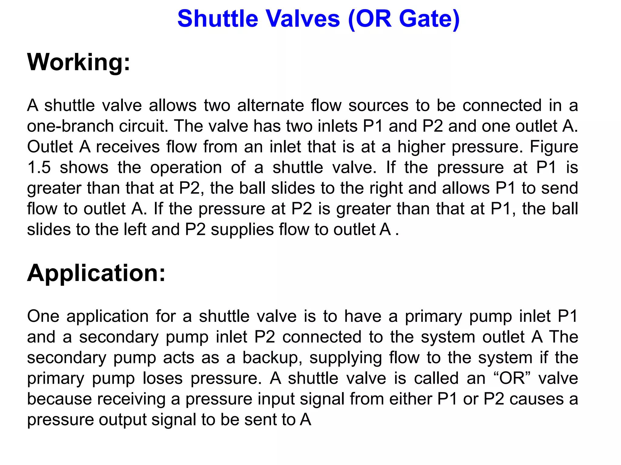
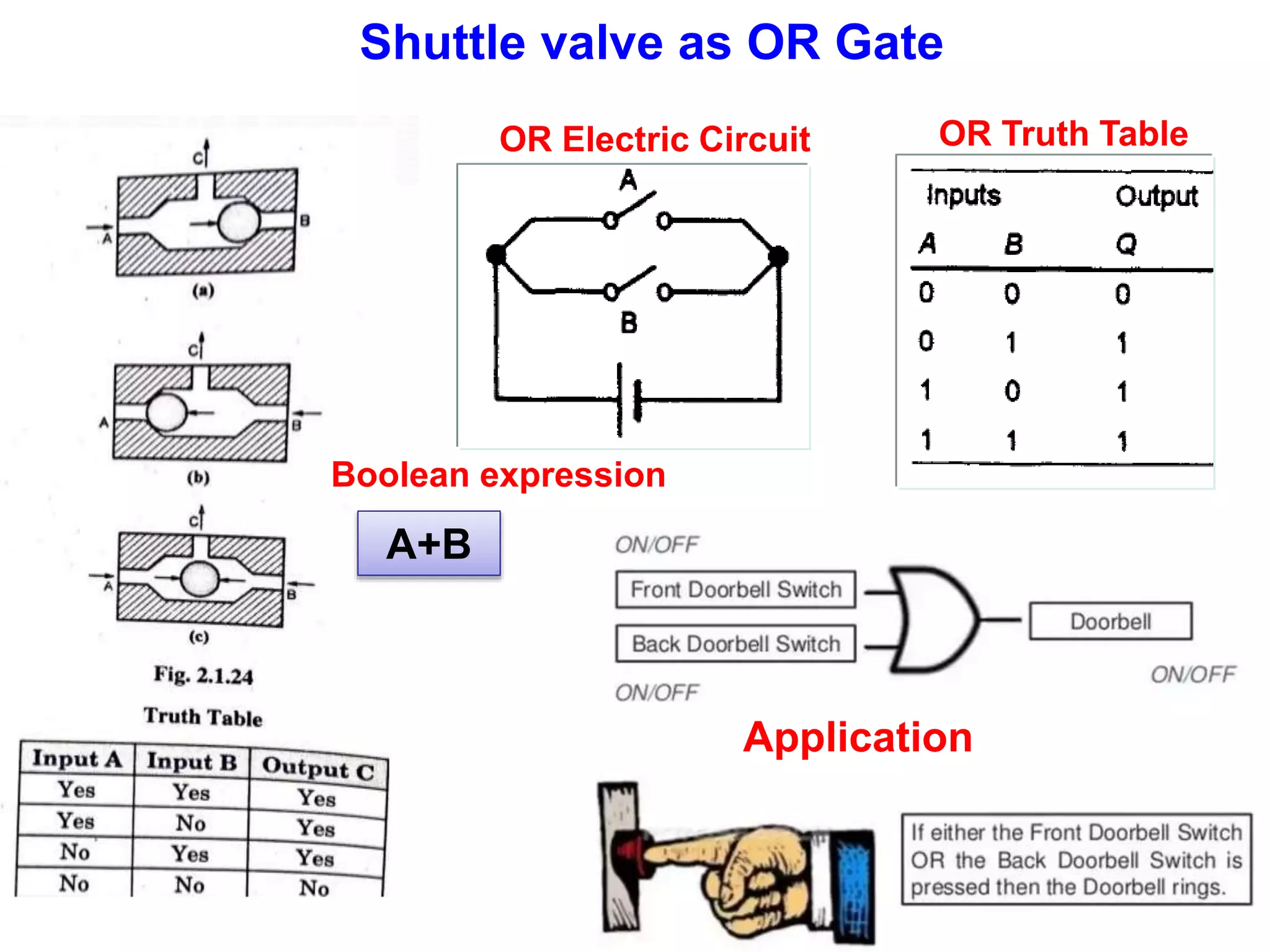
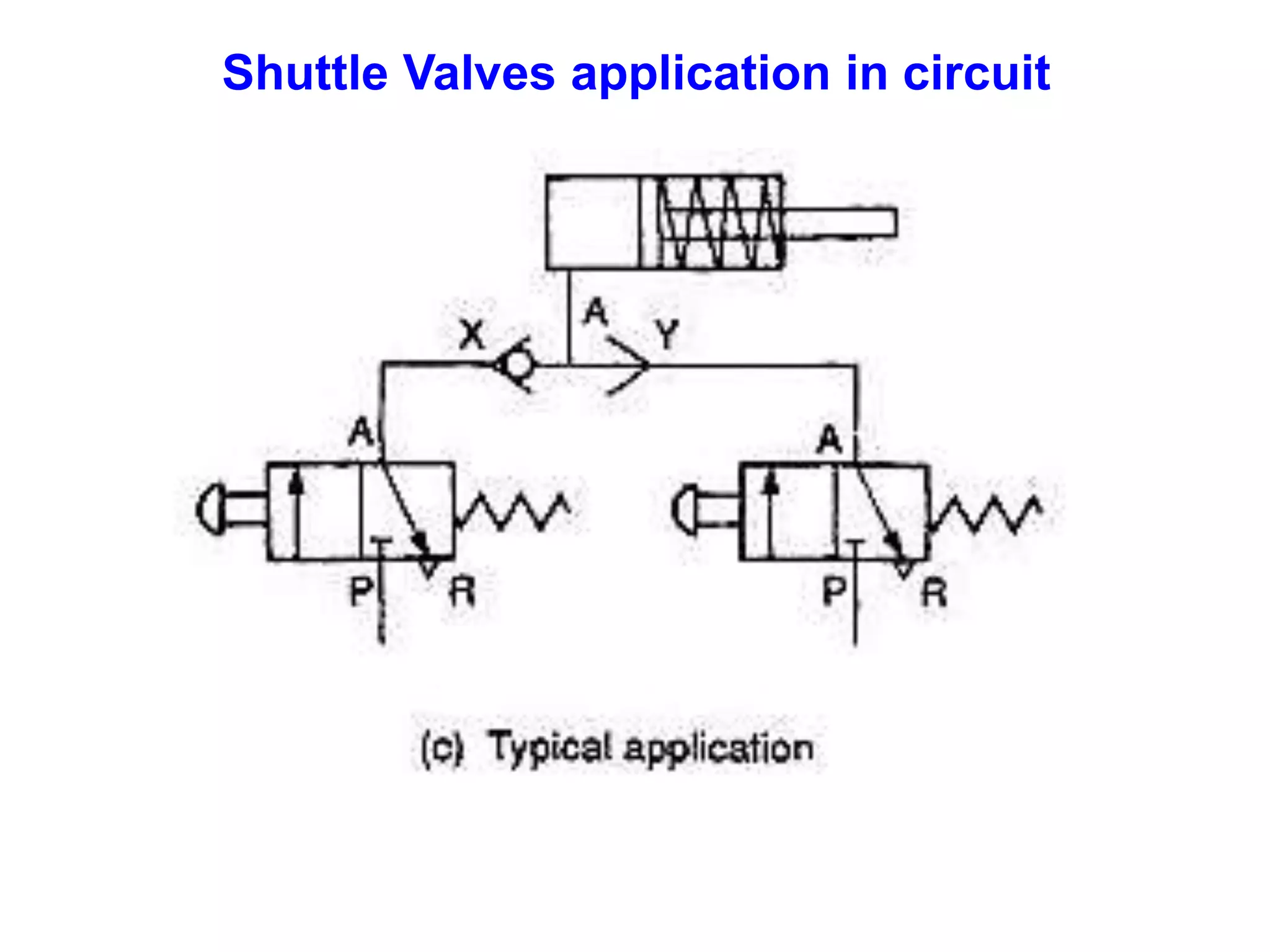
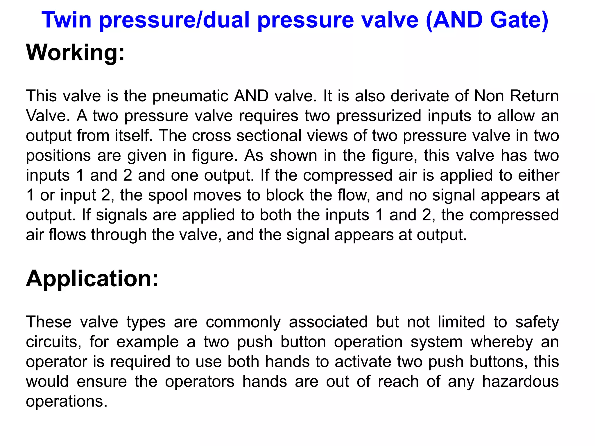
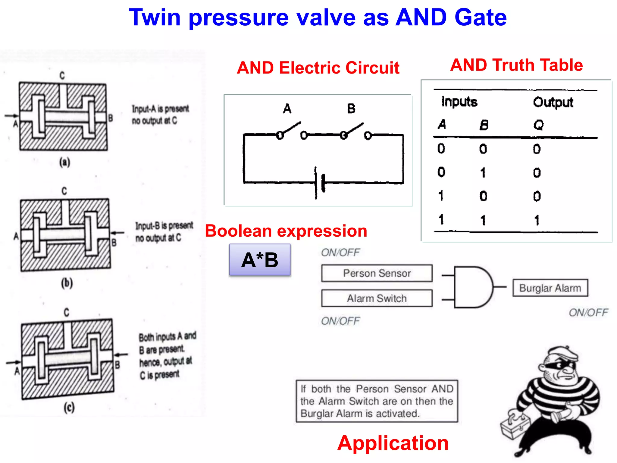
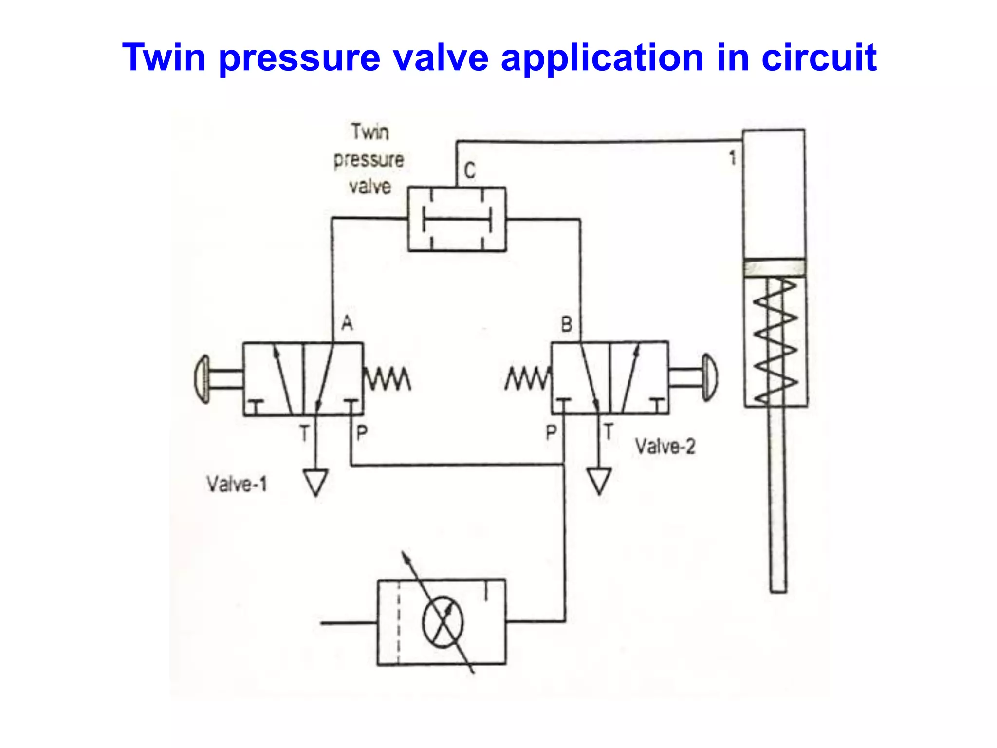
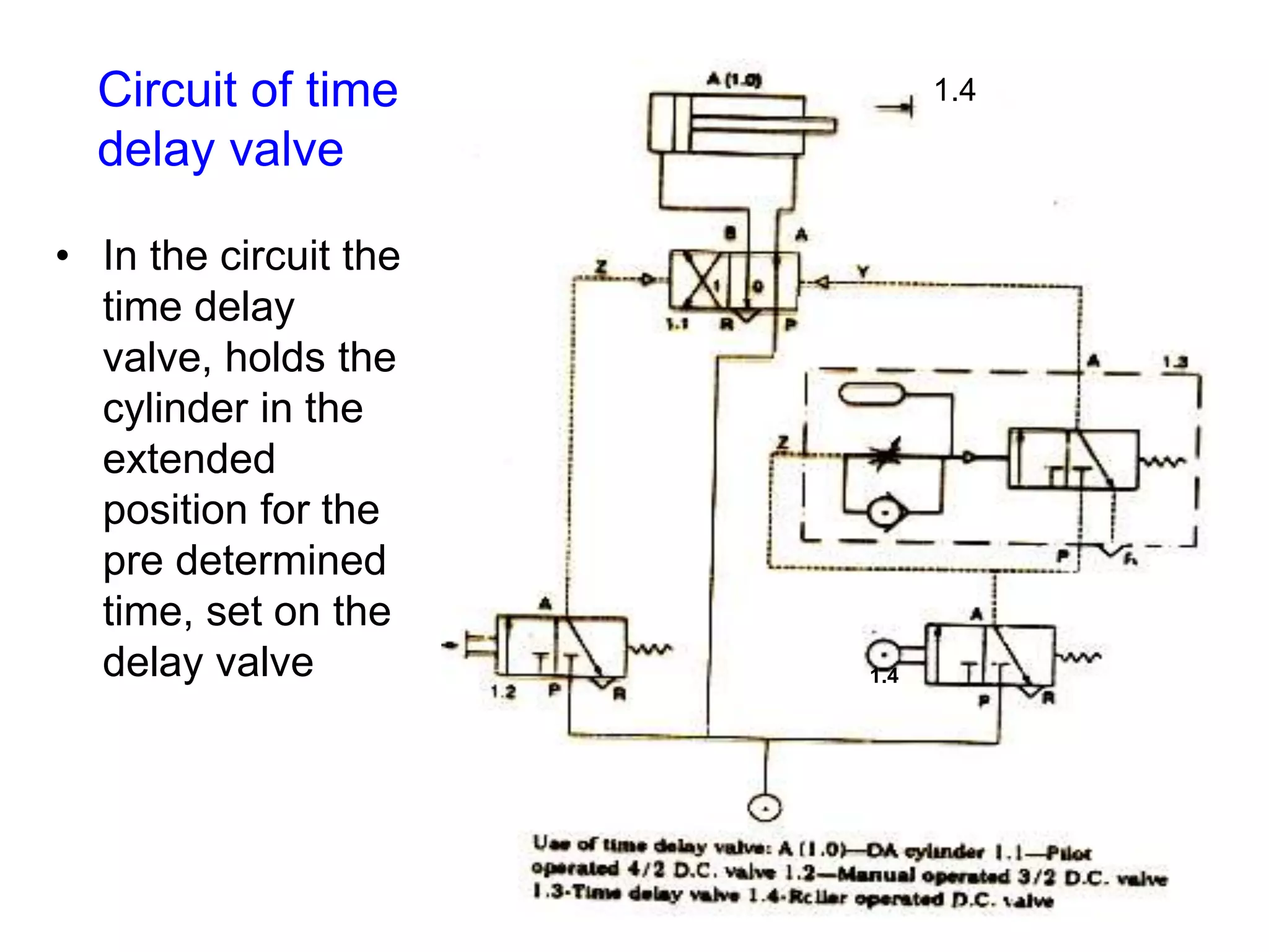
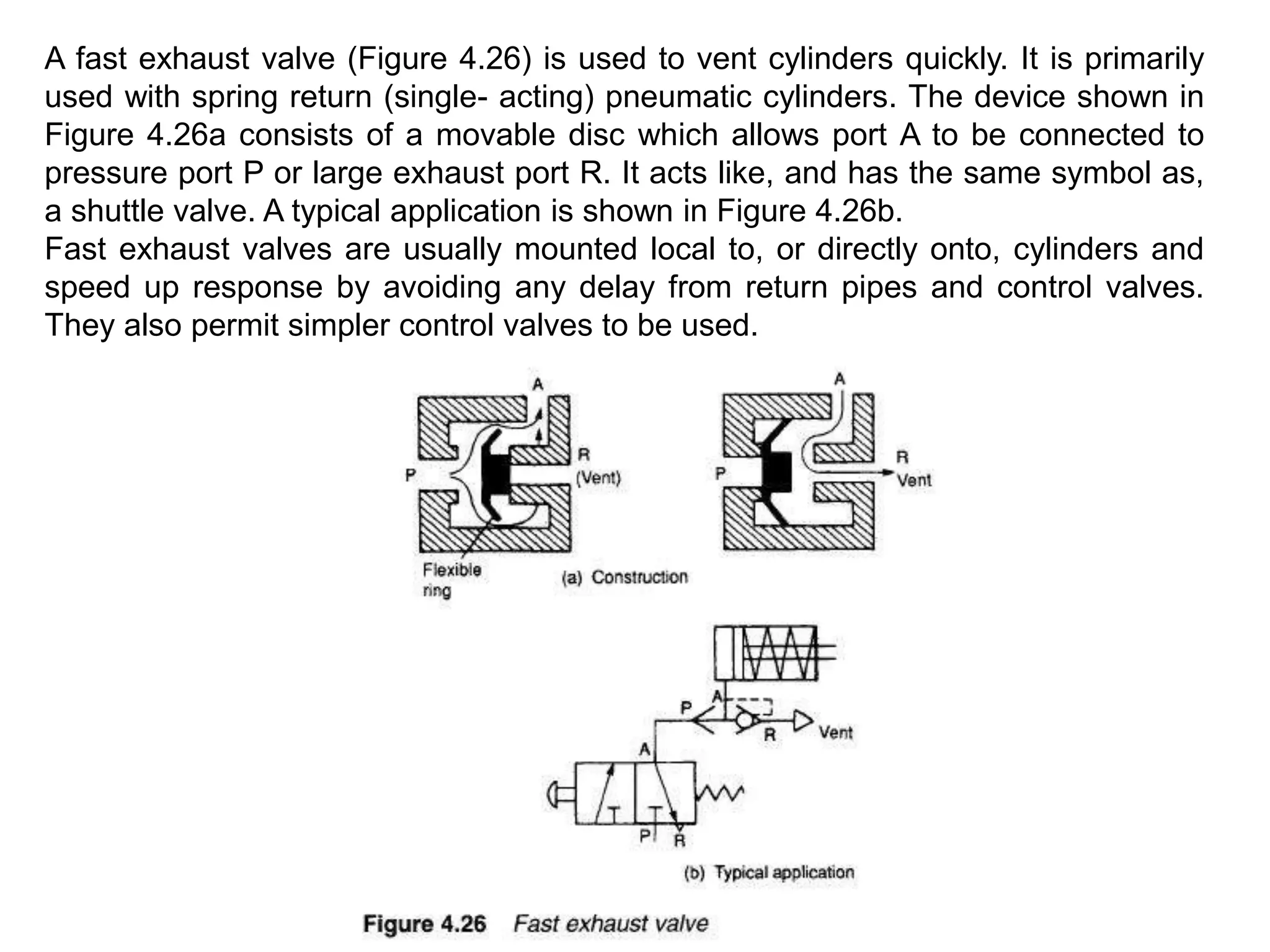
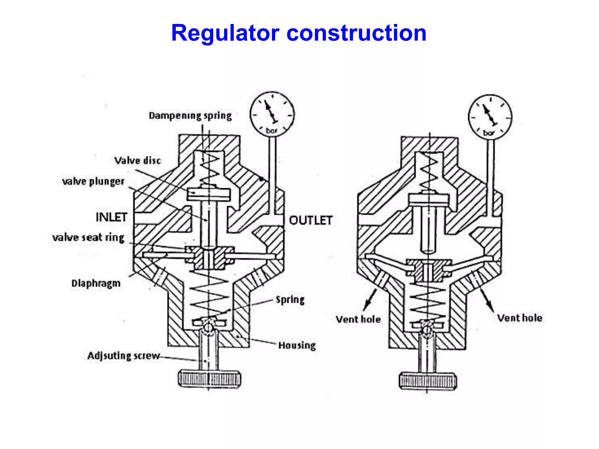
The document discusses various components used in pneumatic systems including logic gates, valves, and FRL units. It begins with explanations of shuttle valves and twin pressure/dual pressure valves that can function as OR and AND logic gates respectively. Various valves are then discussed such as time delay valves, quick exhaust valves, and their applications. Speed control methods and the stick-slip effect in pneumatics are also covered. Finally, the construction and working of the main components of an FRL (filter, regulator, lubricator) unit are explained in detail with diagrams.