The document provides an overview of hydraulic valves, detailing their functions, types, and operational principles. It specifically covers directional control valves, symbol designations, connection configurations, and various kinds of valves including pressure control and non-return valves. Additionally, it explains flow rate control and the applications of pressure relief and reducing valves in hydraulic systems.
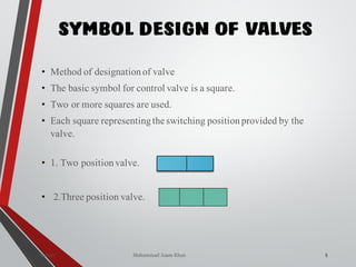
![Mohammad Azam Khan [M.Tech- Industrial and Production]
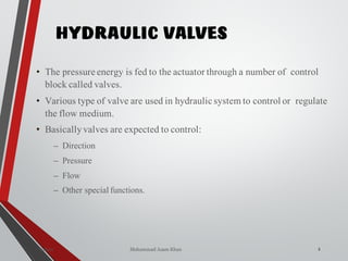
HYDRAULIC
1Valves
VALVES](https://image.slidesharecdn.com/07hydraulicvalves-180612224109/85/Hydraulic-Valves-Valves-Pneumatics-also-1-320.jpg)
![Mohammad Azam Khan [M.Tech- Industrial and Production]
HYDRAULIC
1Valves
VALVES](https://image.slidesharecdn.com/07hydraulicvalves-180612224109/75/Hydraulic-Valves-Valves-Pneumatics-also-1-2048.jpg)
![WAY/POSITION
10
Way Valve Ports Positions
2/2
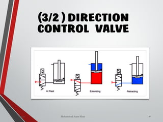
3/2
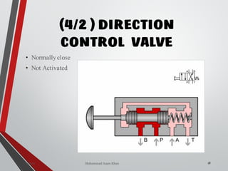
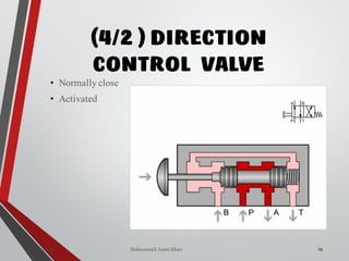
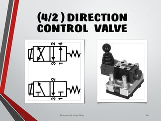
4/2
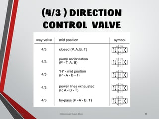
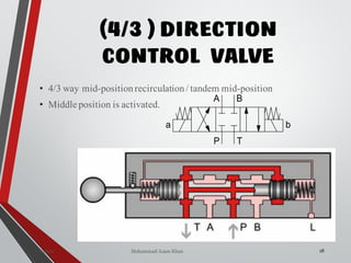
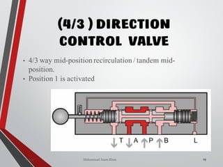
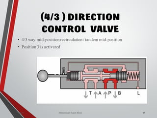
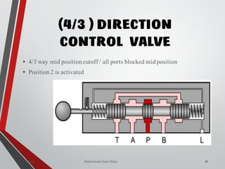
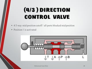
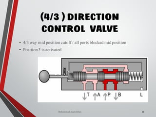
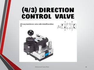
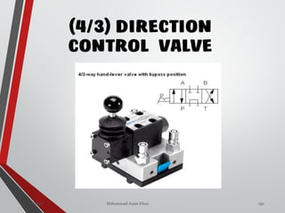
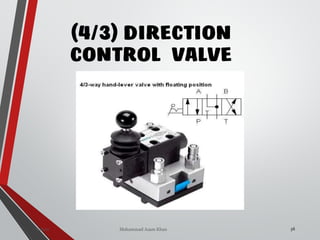
4/3
2.(1 inputs, 1 output) 2
3.(1 input, 1 output, 1 tank) 2
4.(1 input,2 output, 1 tank) 2
4 (1 input, 2 output, 1 tank) 3
Mechatronics]
Valves Sanjay Humania[M.Tech-](https://image.slidesharecdn.com/07hydraulicvalves-180612224109/85/Hydraulic-Valves-Valves-Pneumatics-also-10-320.jpg)
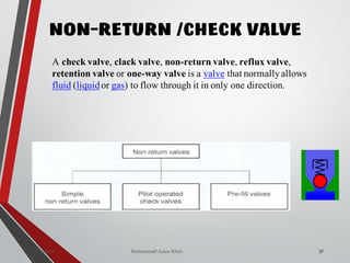
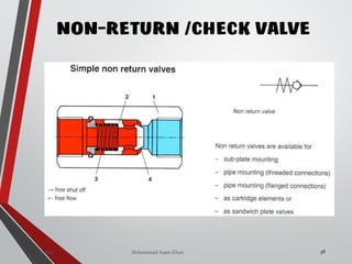
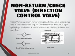
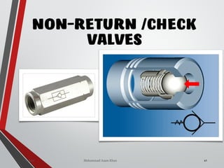
![NON-RETURN /CHECK
VALVE (DIRECTION
CONTROL VALVE)
ania [M.Tech- Mechatronics] 155Valves SanjayHum](https://image.slidesharecdn.com/07hydraulicvalves-180612224109/85/Hydraulic-Valves-Valves-Pneumatics-also-40-320.jpg)
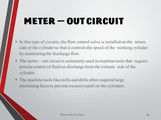

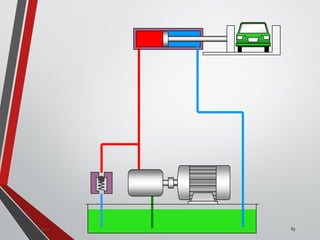
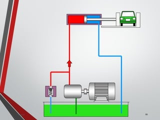


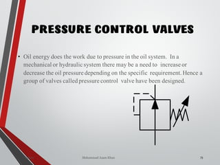
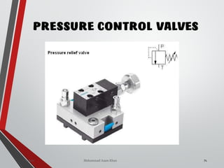
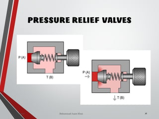
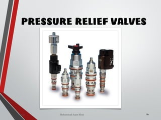
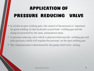
![PRESSURE RELIEF VALVES
75
• Relief valves are generallyspring loaded valves which include a plug
over a discharge port which is liftedagainst an spring force if the
system pressure exceeds a certainvalue. This opens the flow to the
discharge port relieving the pressure.
Sanjay Humania [M.Tech- MechatronicsValves ]](https://image.slidesharecdn.com/07hydraulicvalves-180612224109/85/Hydraulic-Valves-Valves-Pneumatics-also-75-320.jpg)