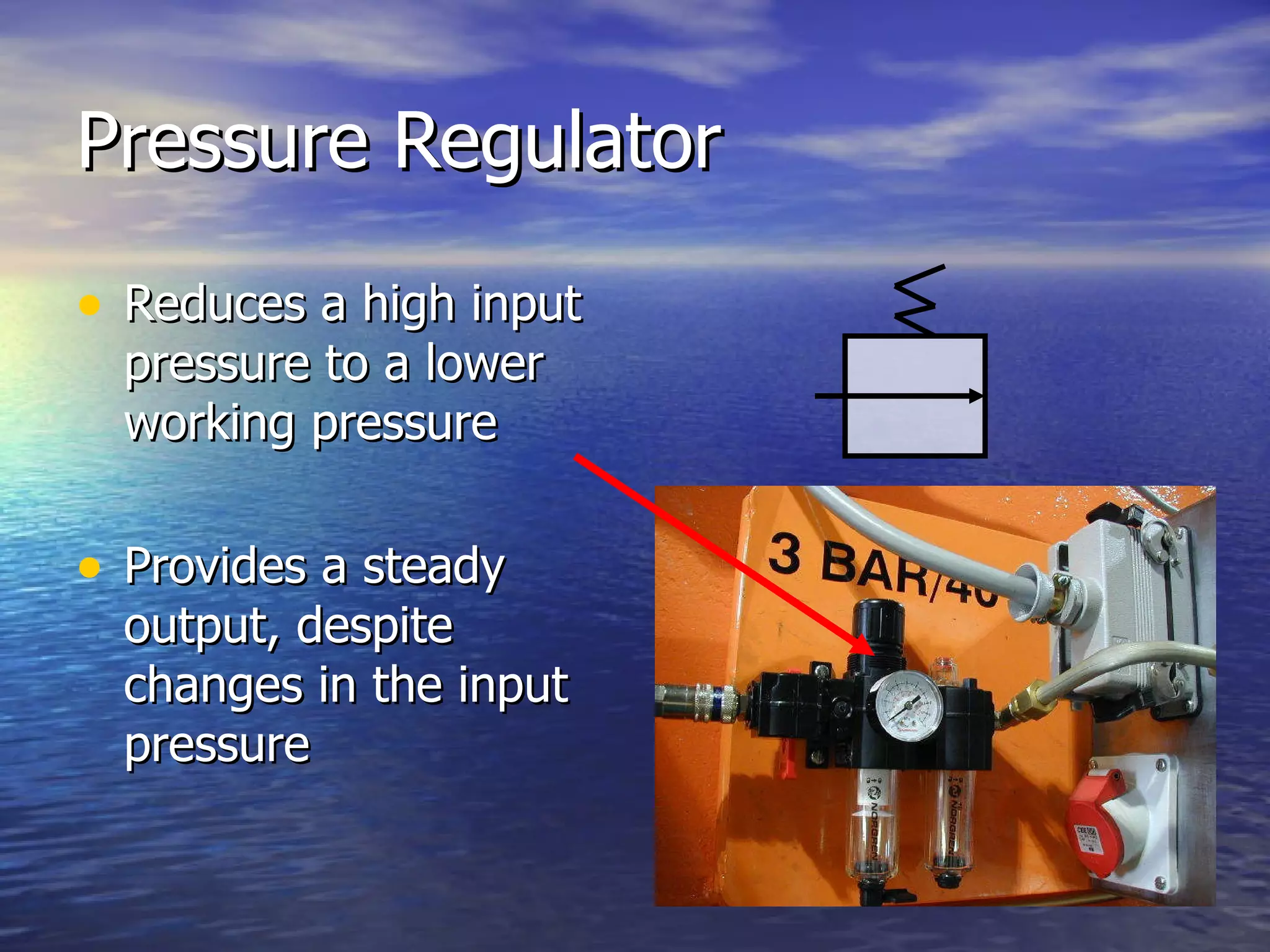
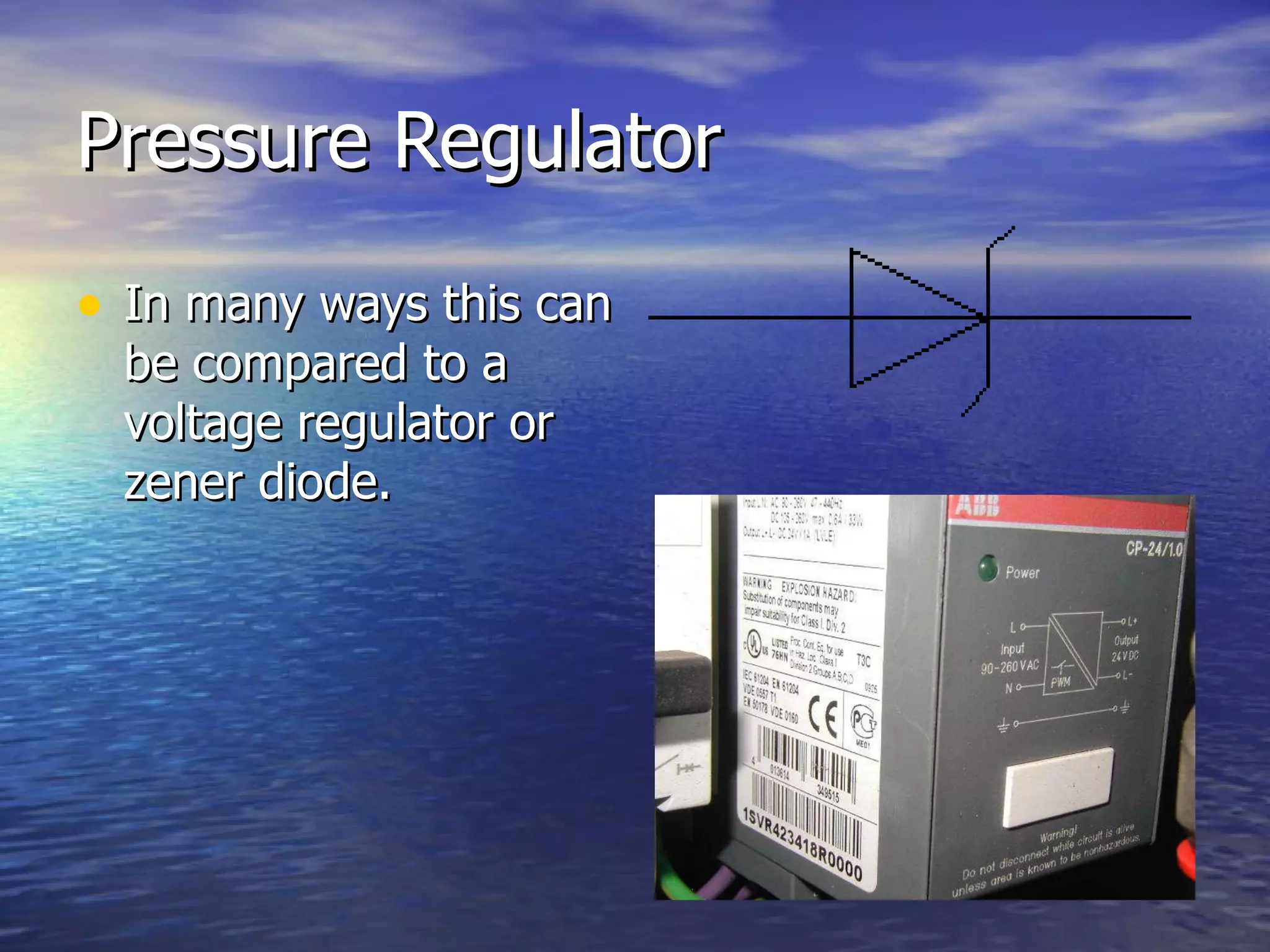
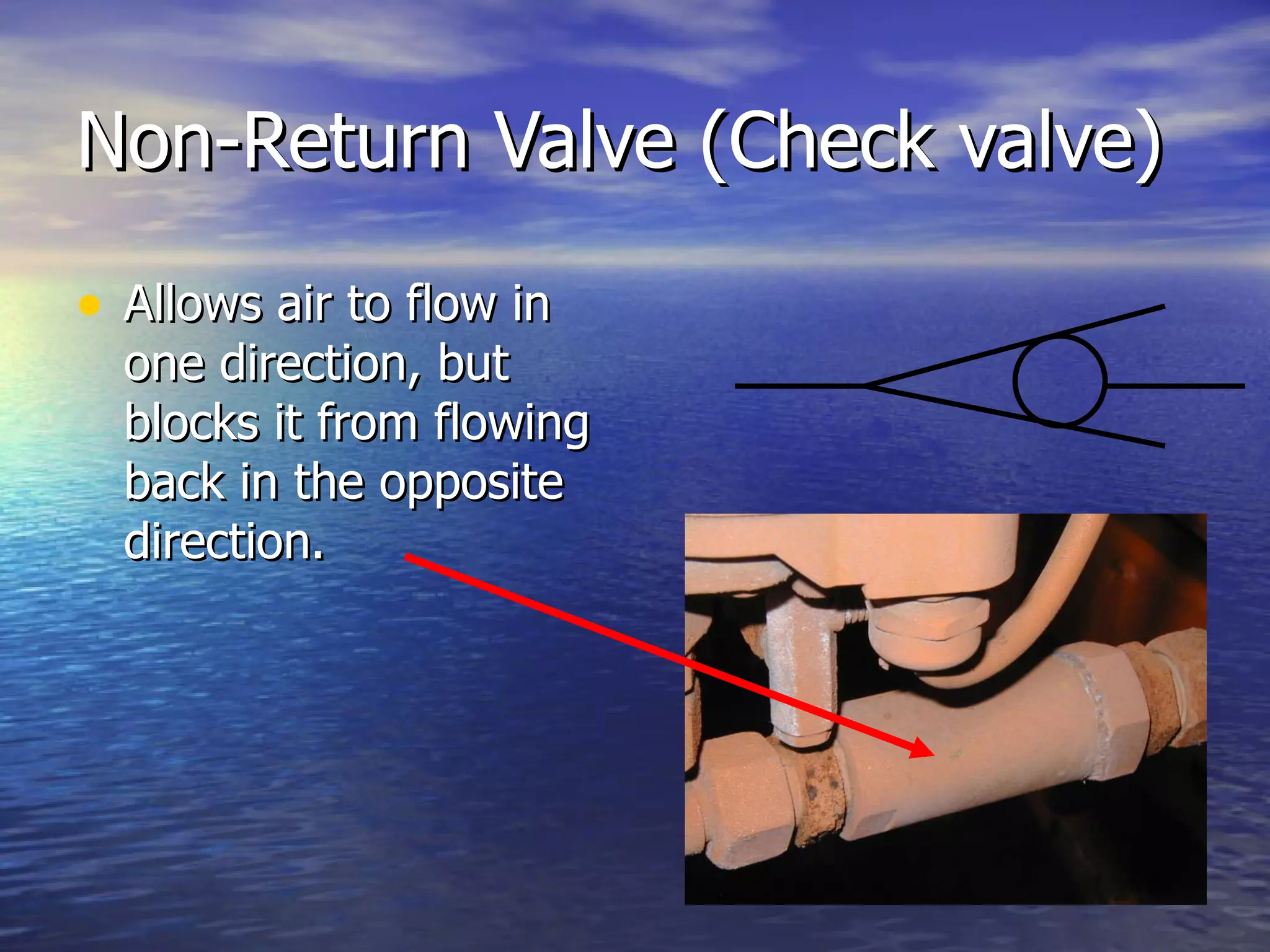
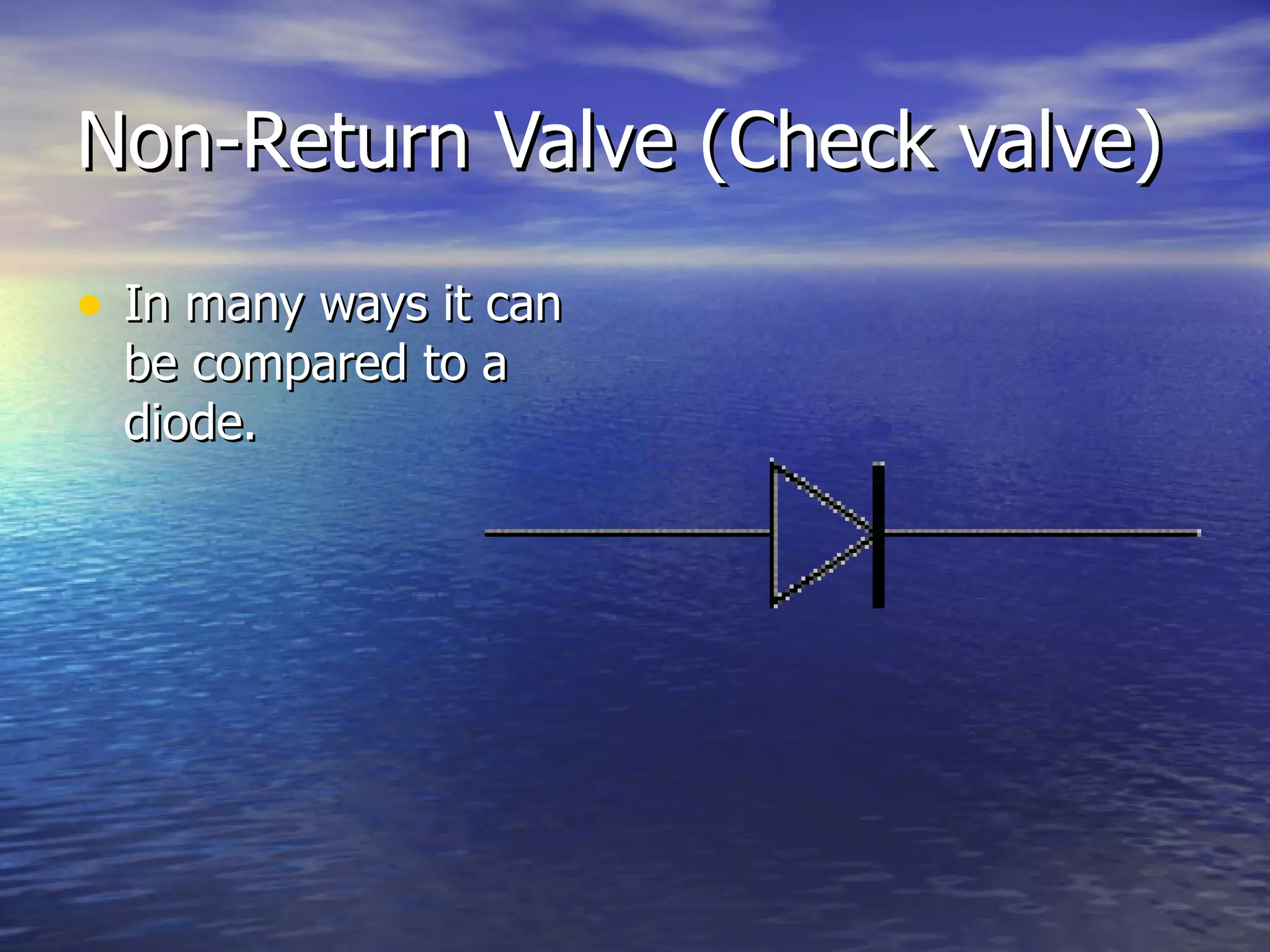
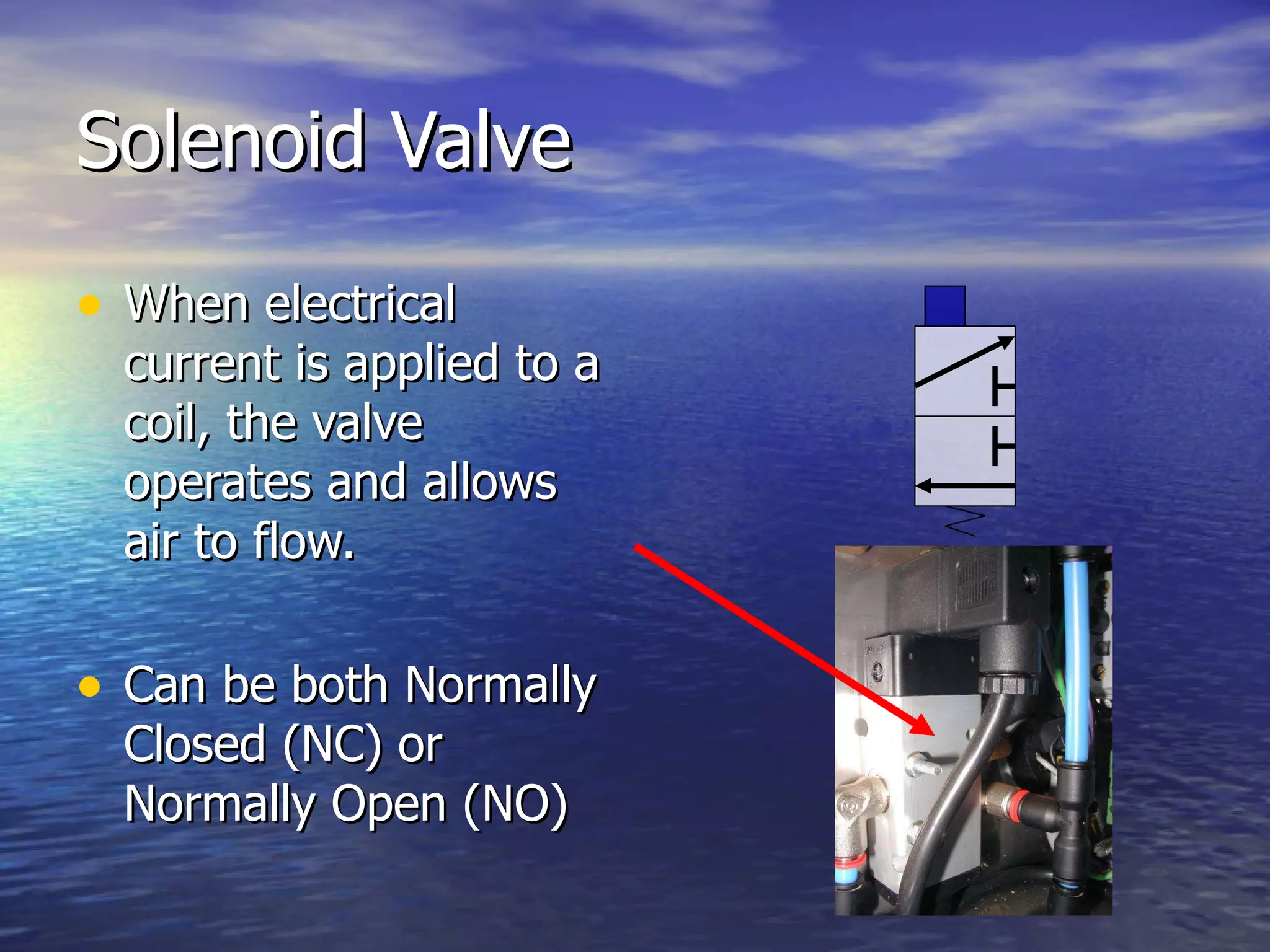
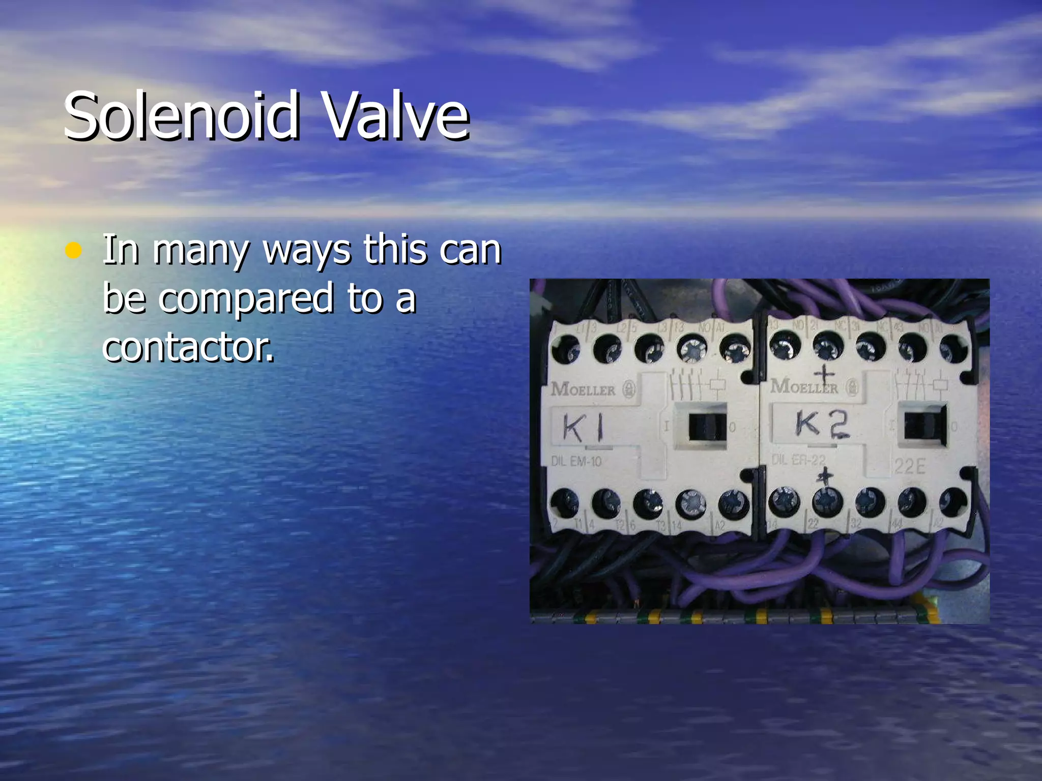
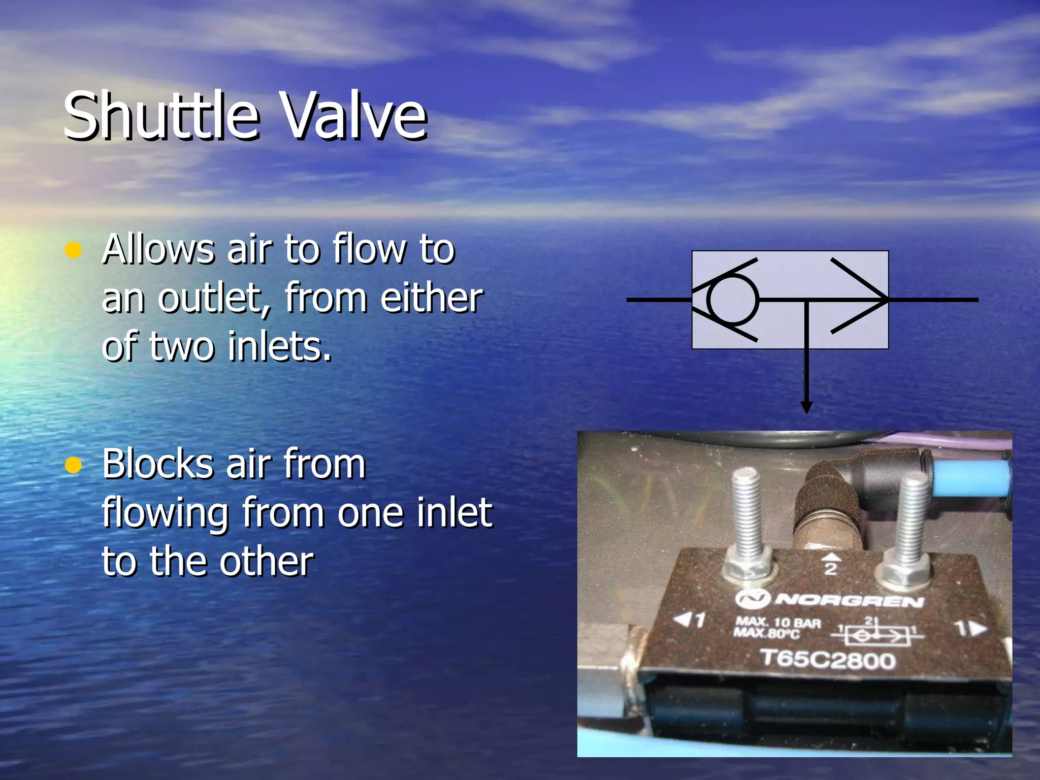
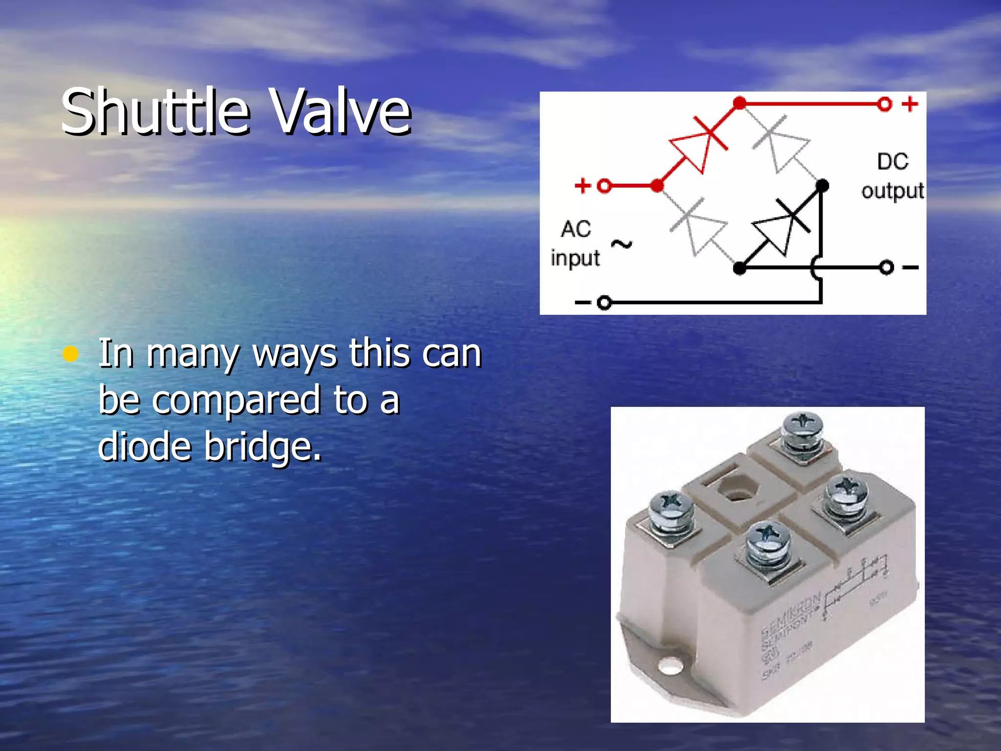
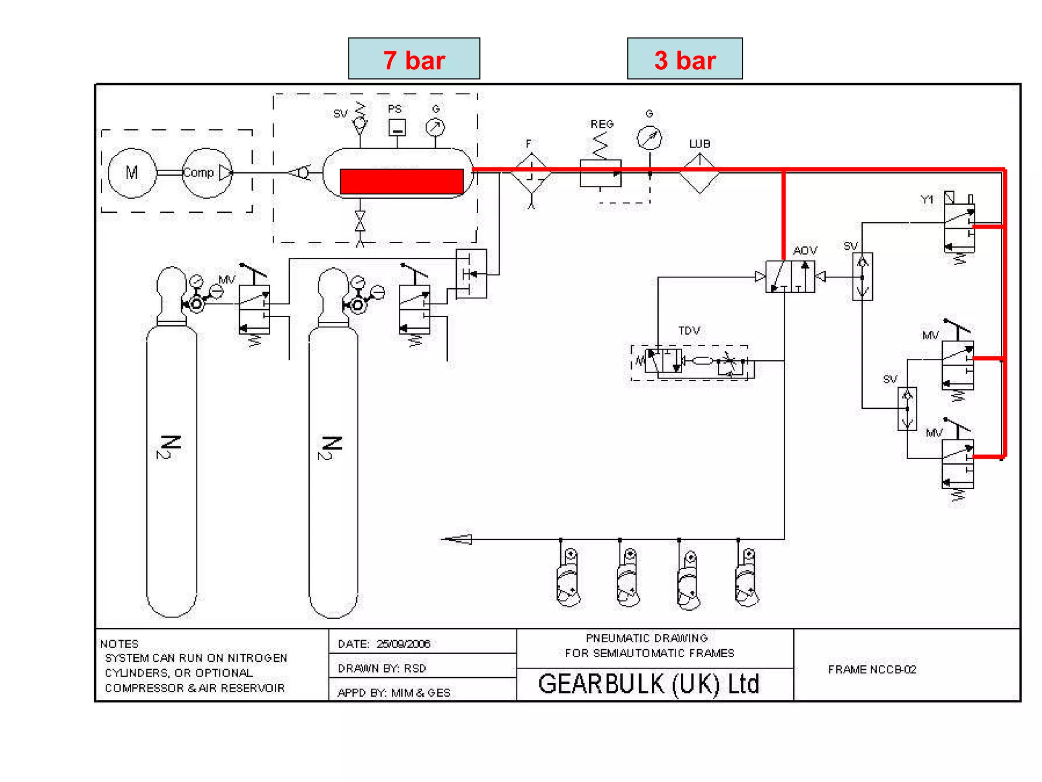
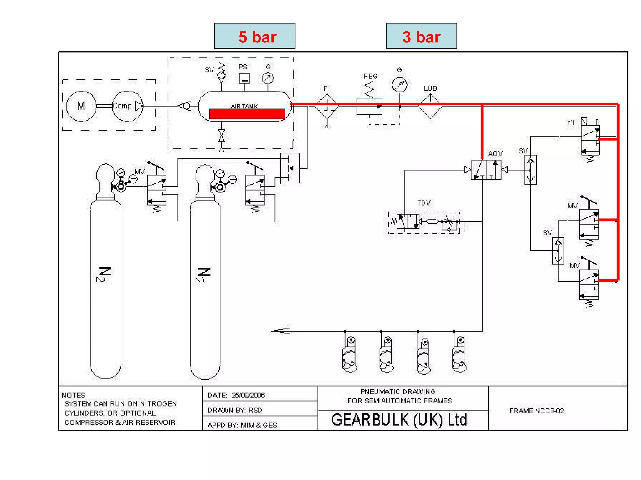
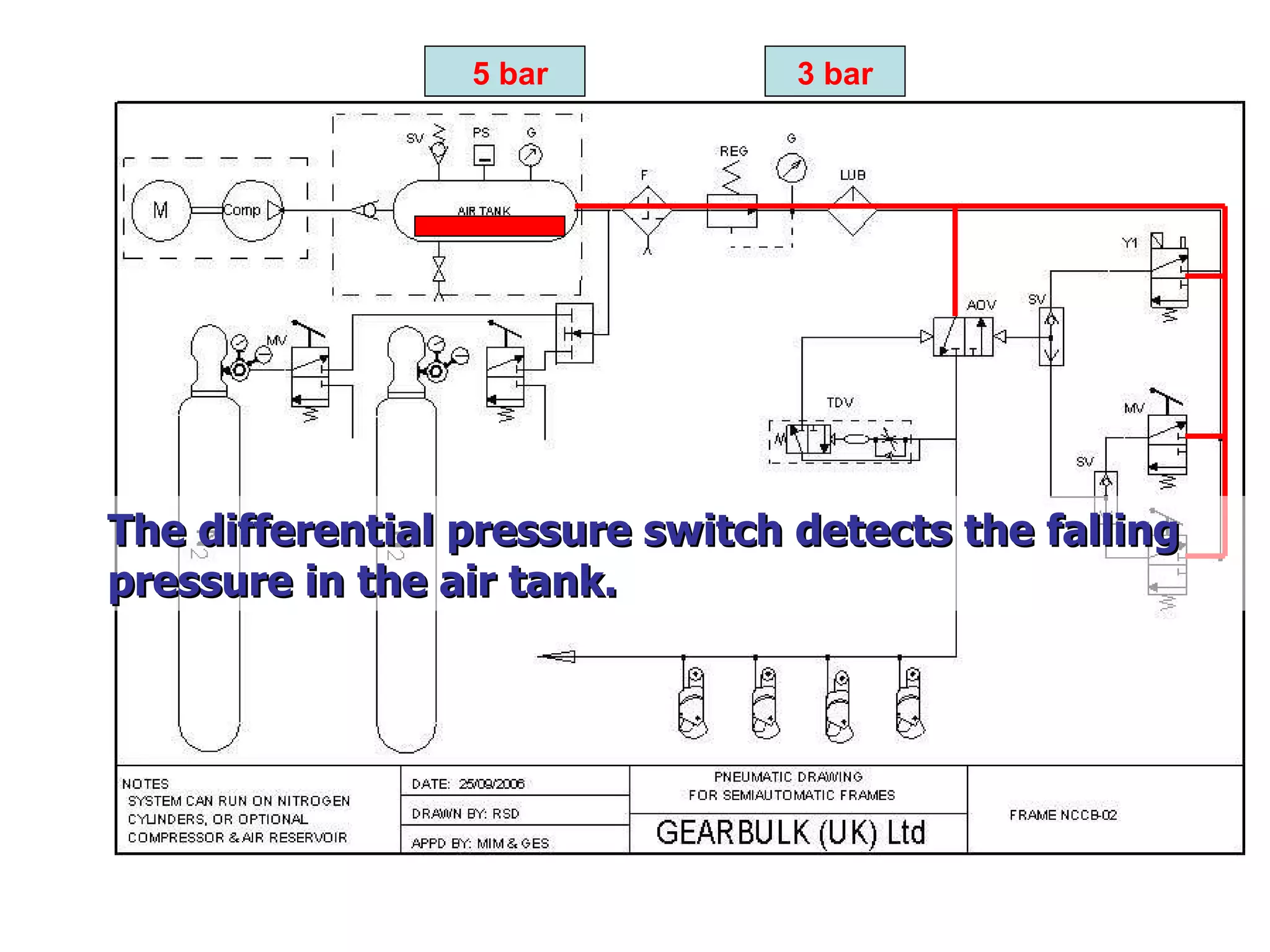
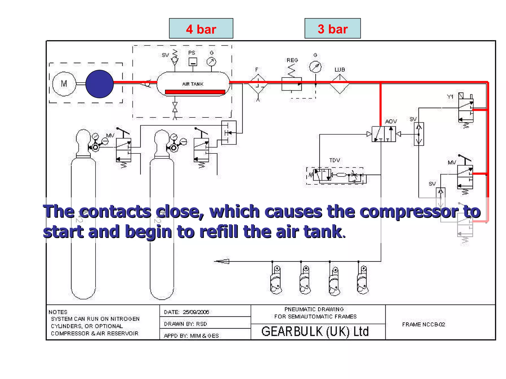
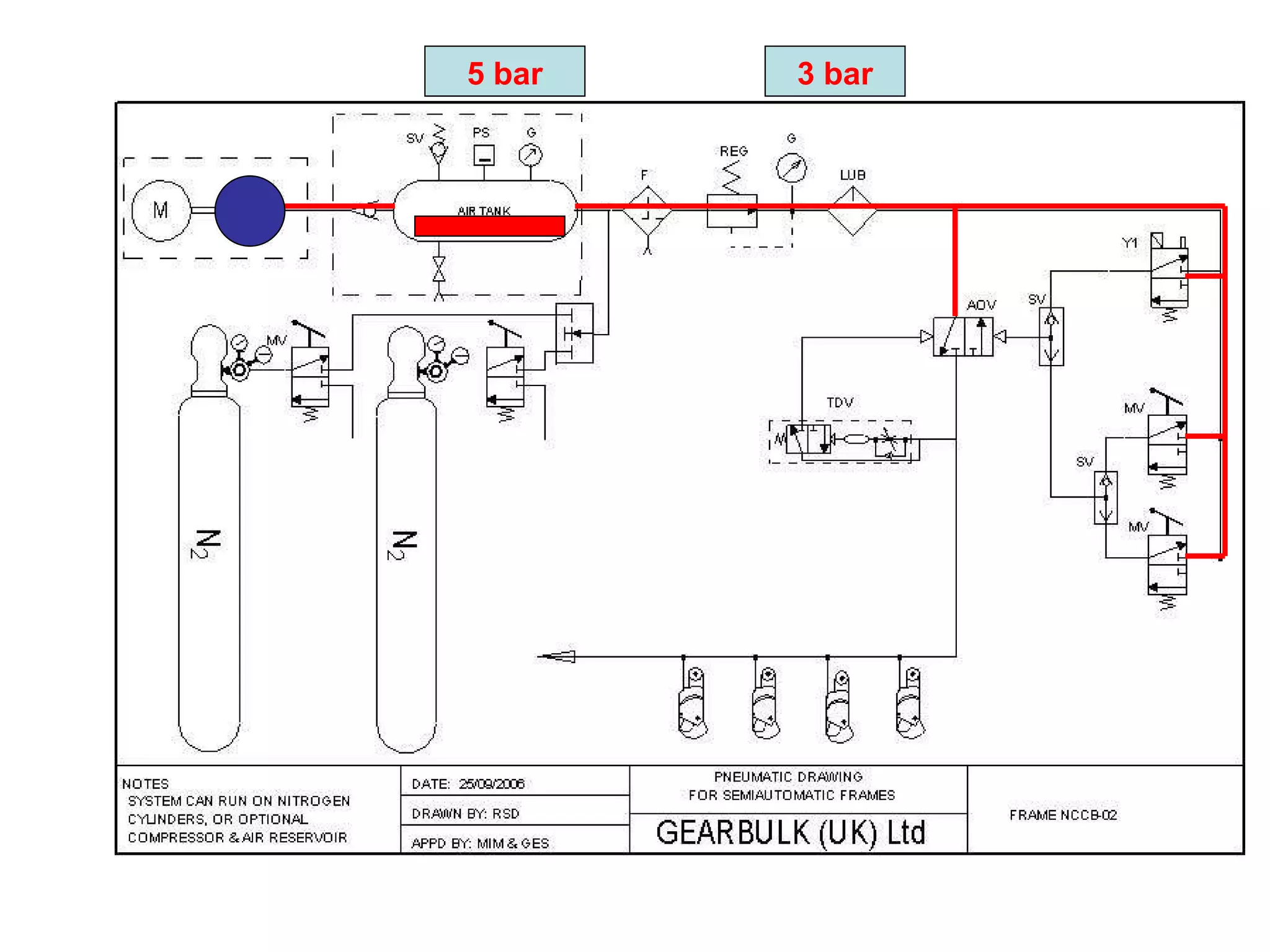
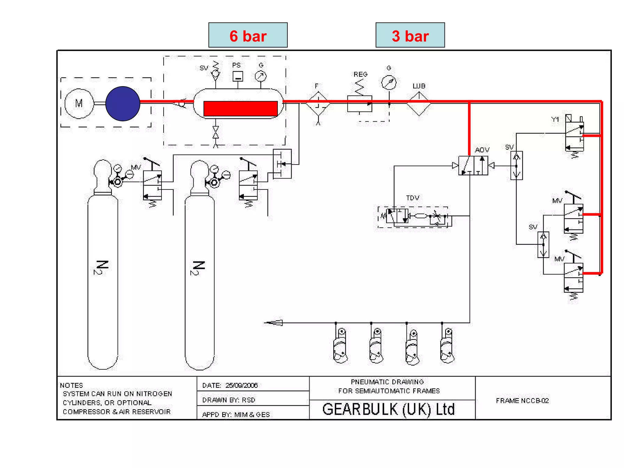
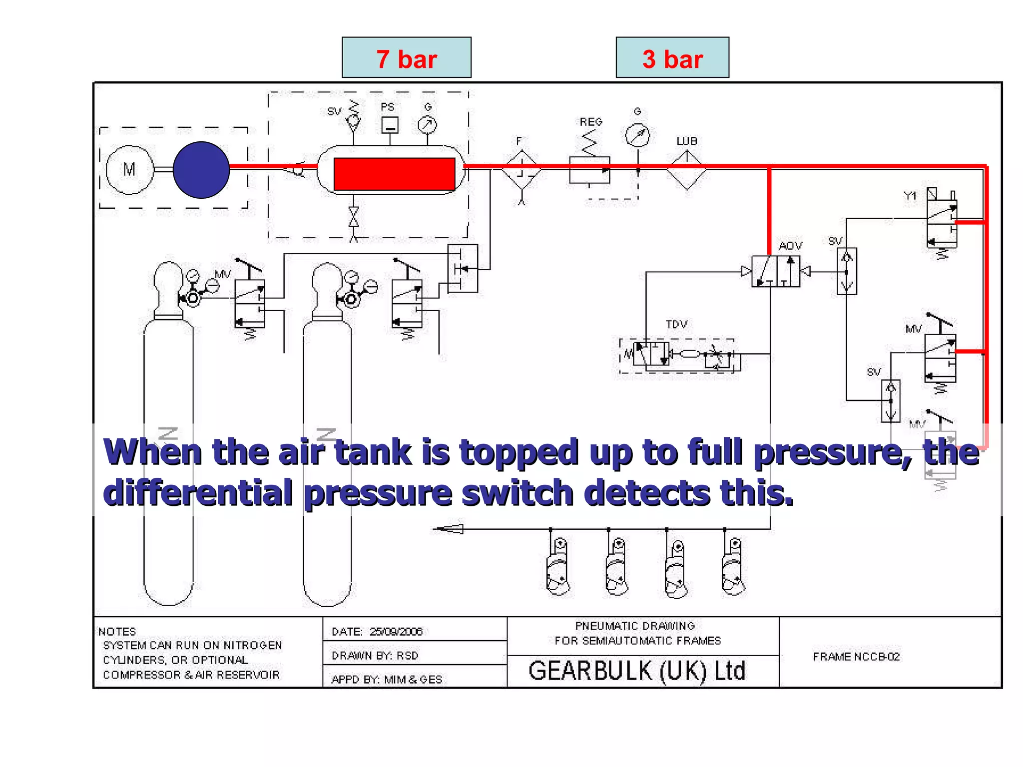
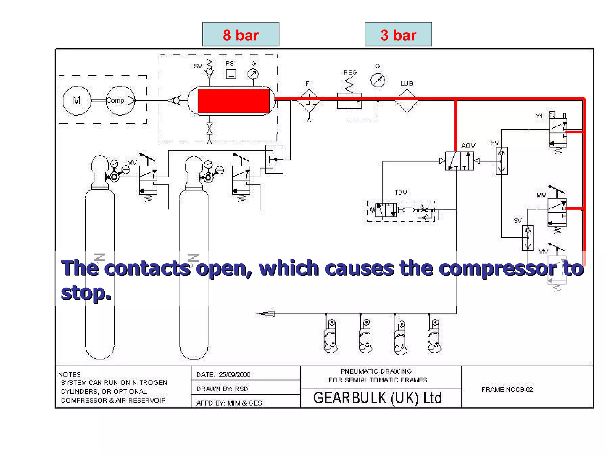
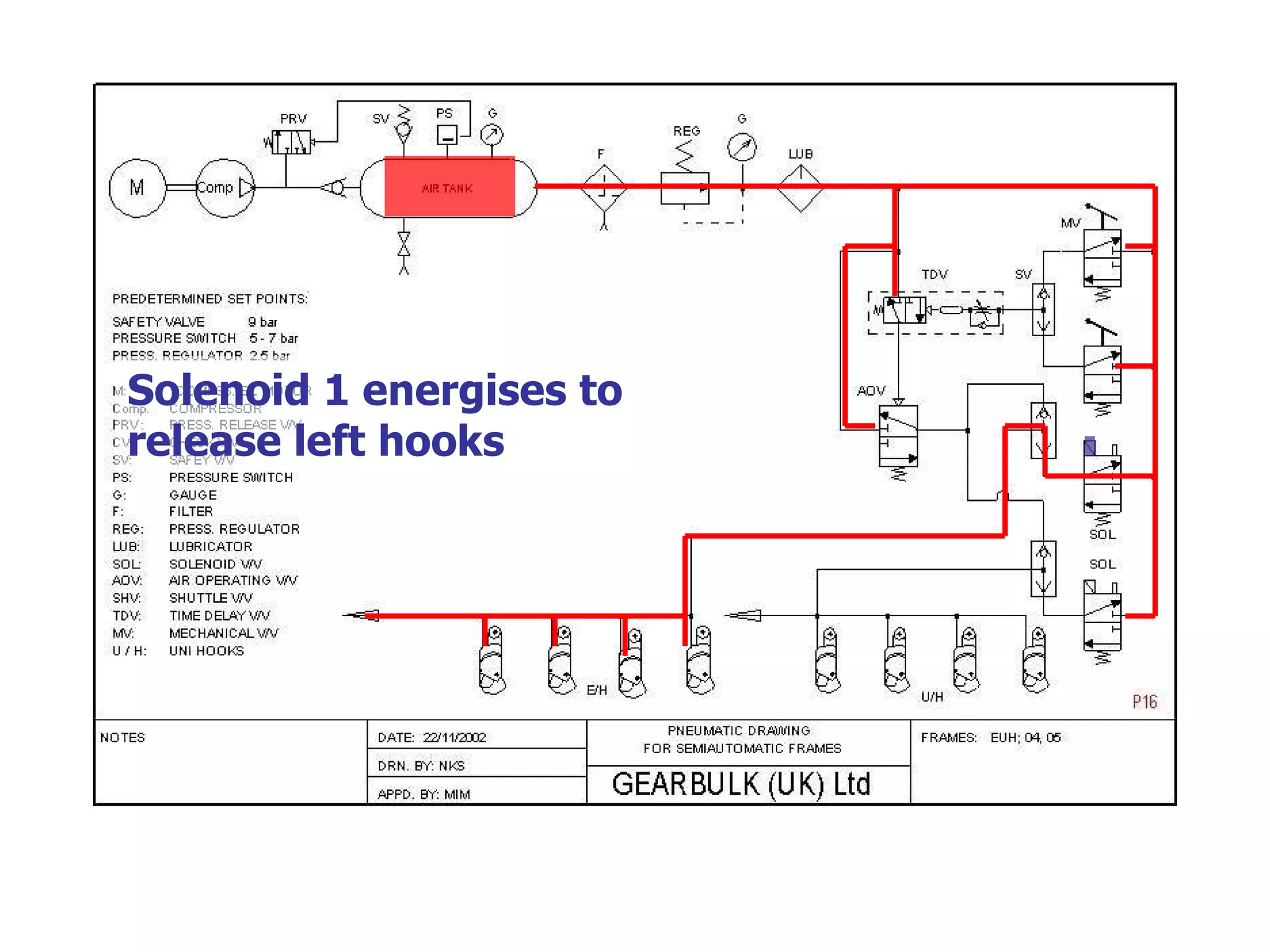
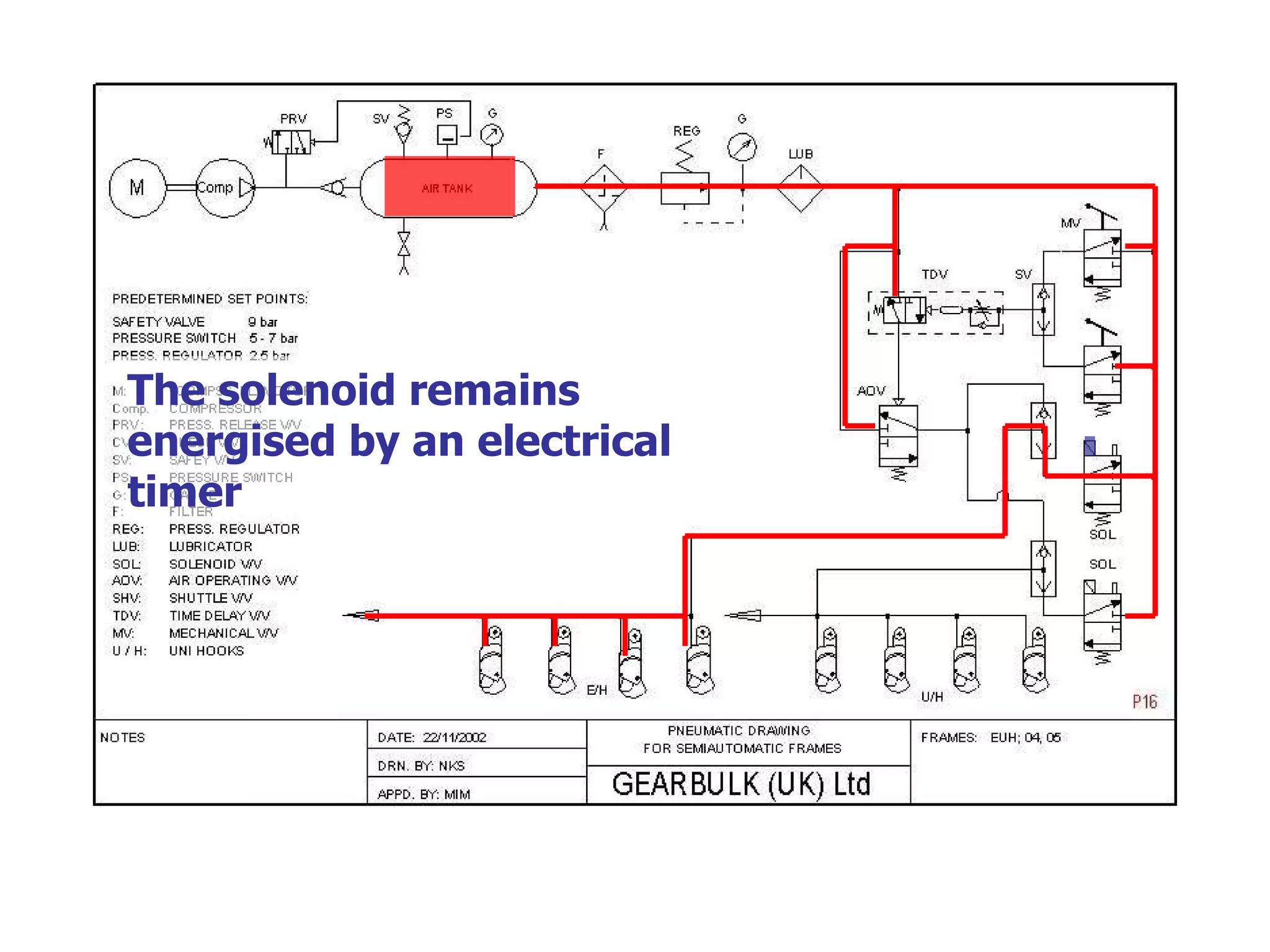
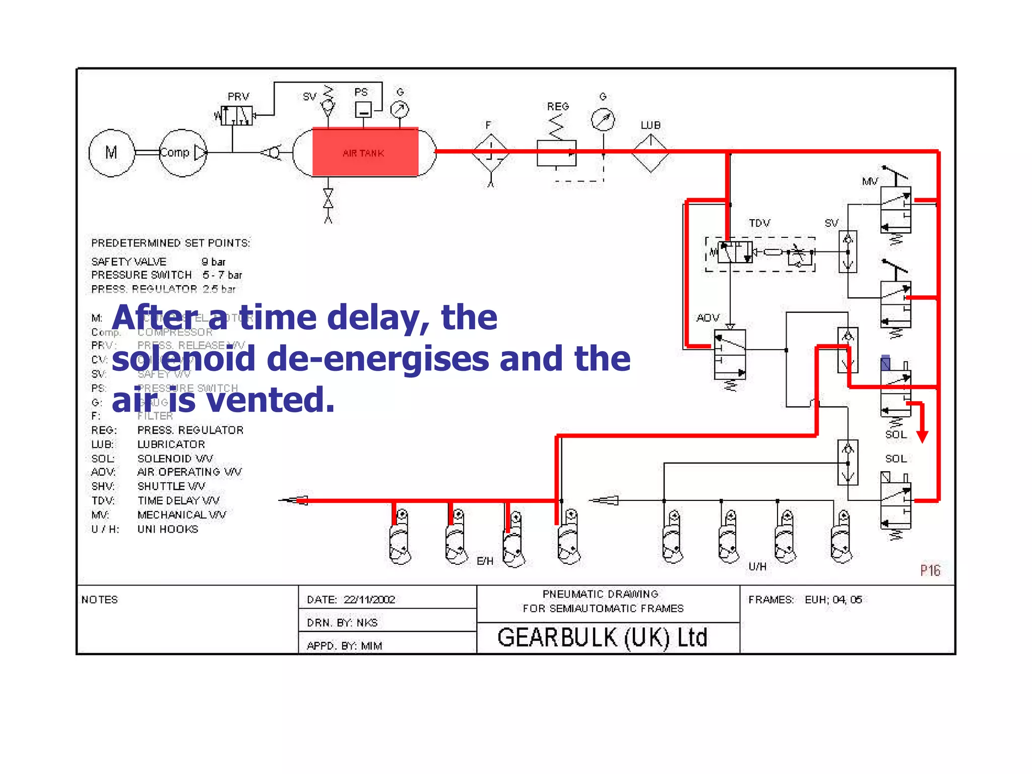
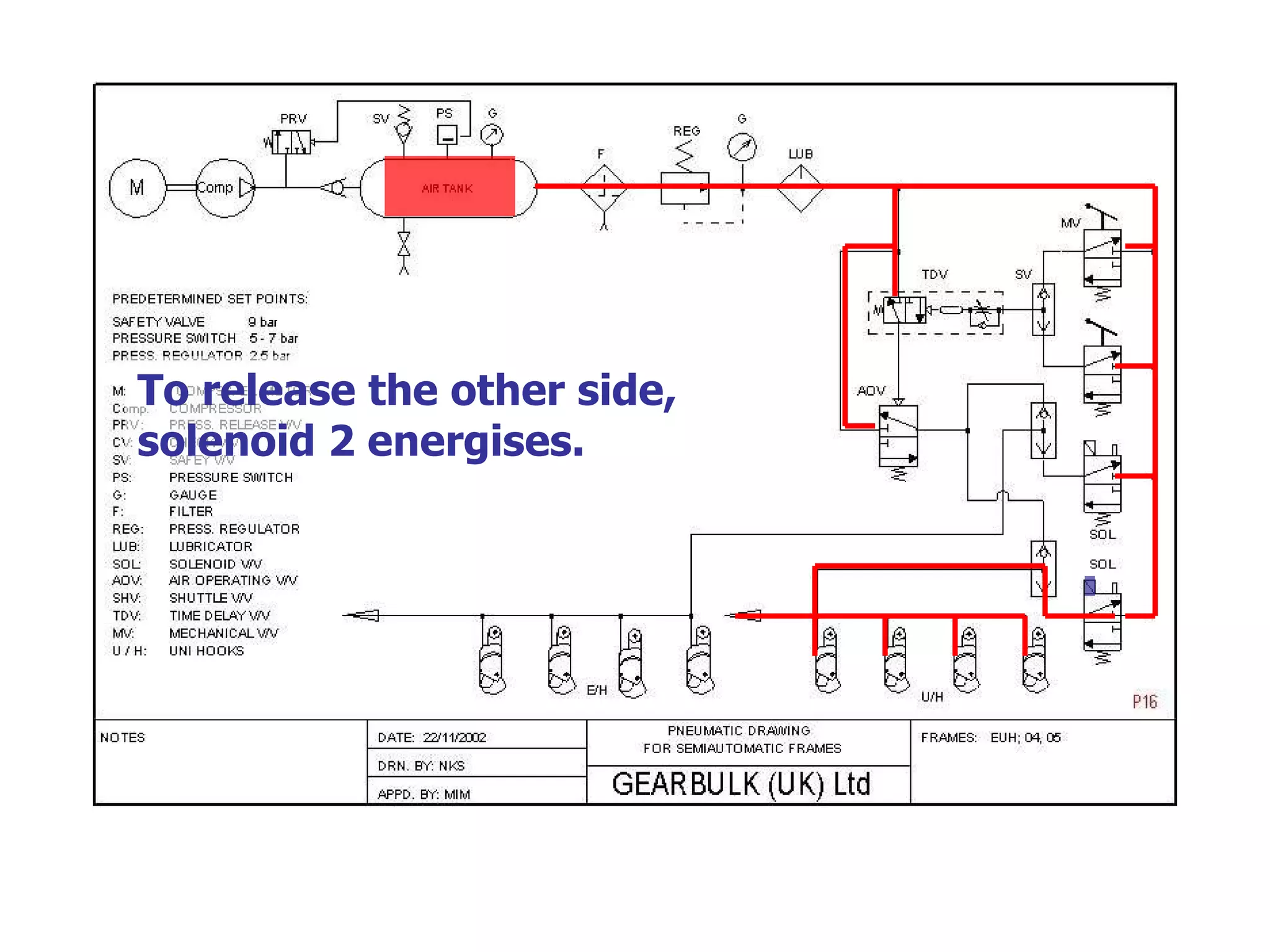
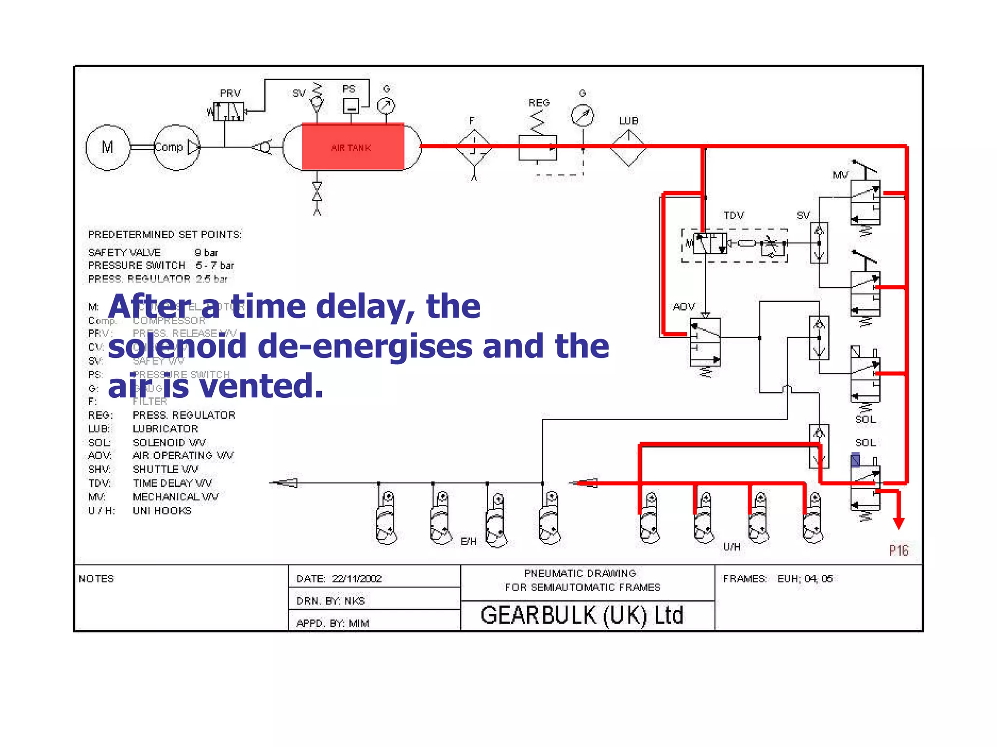
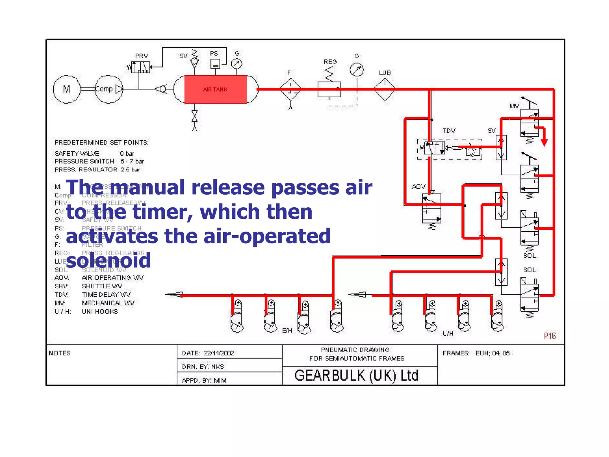
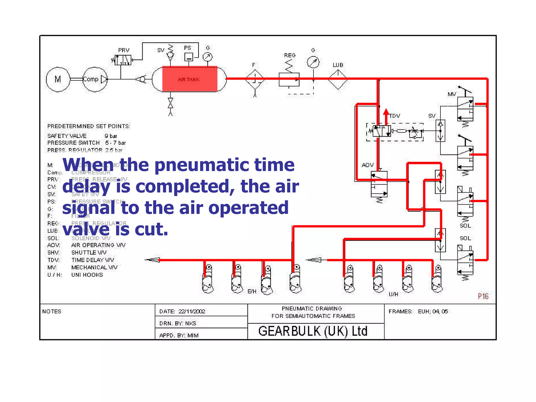
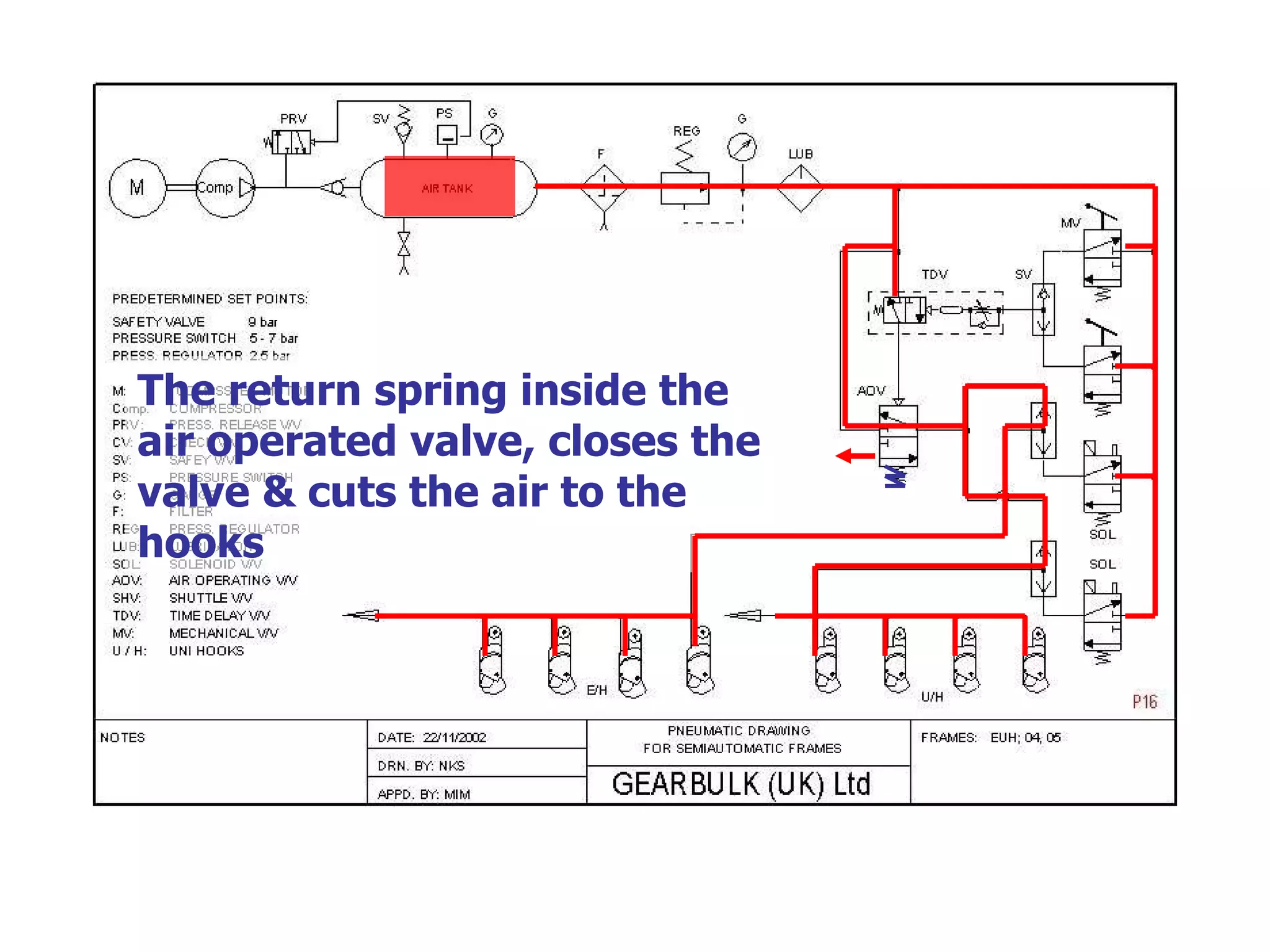
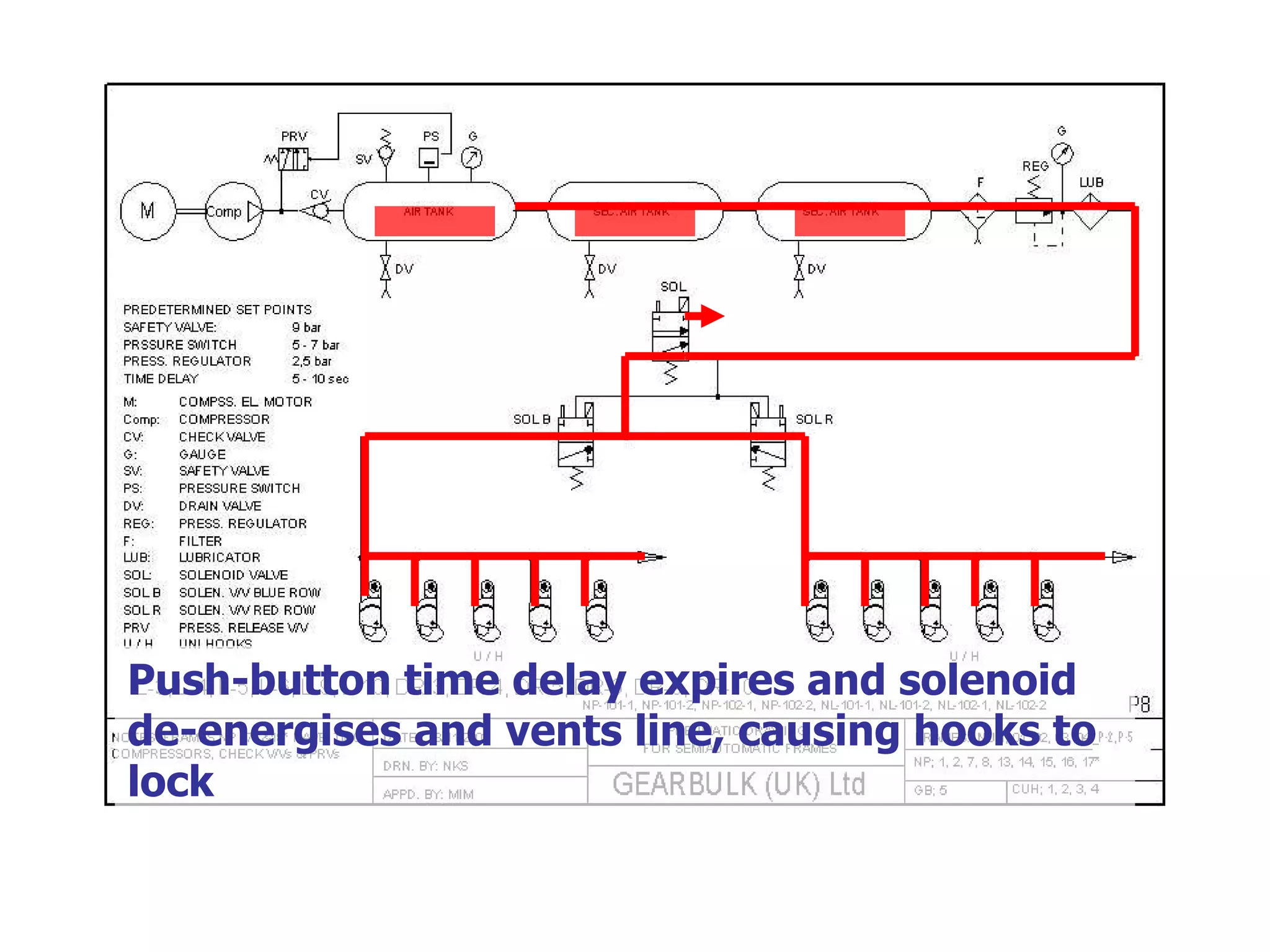
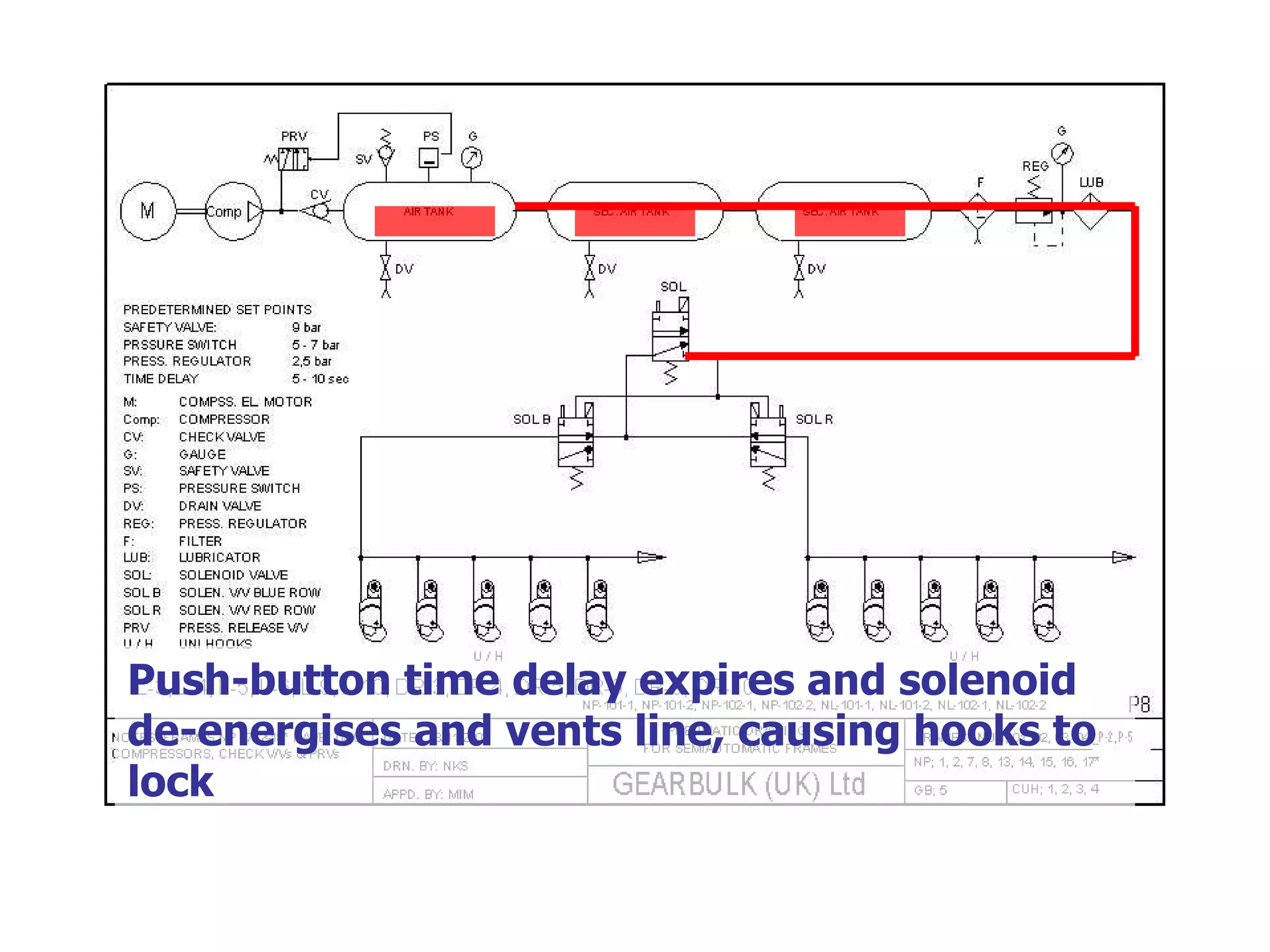
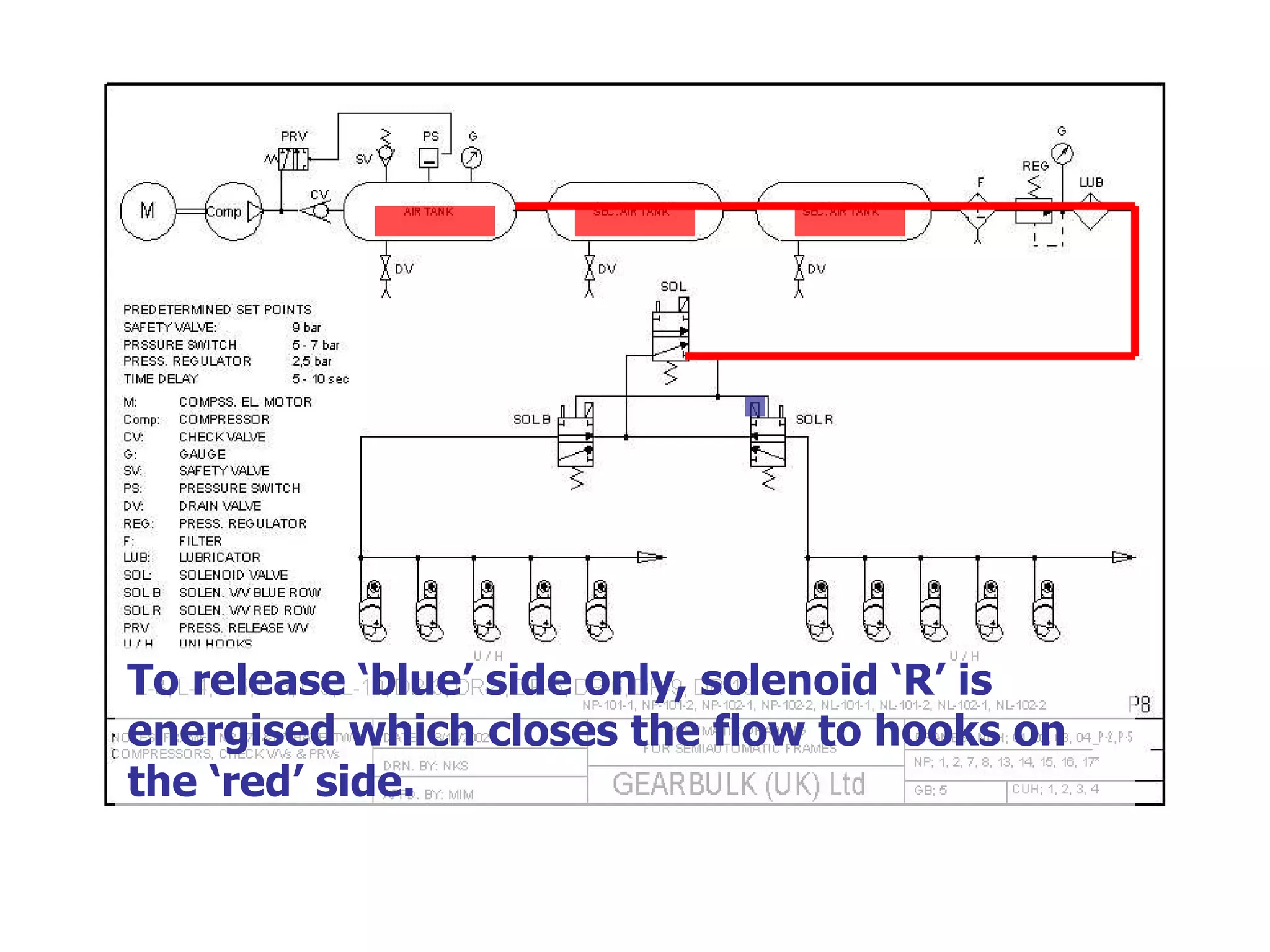
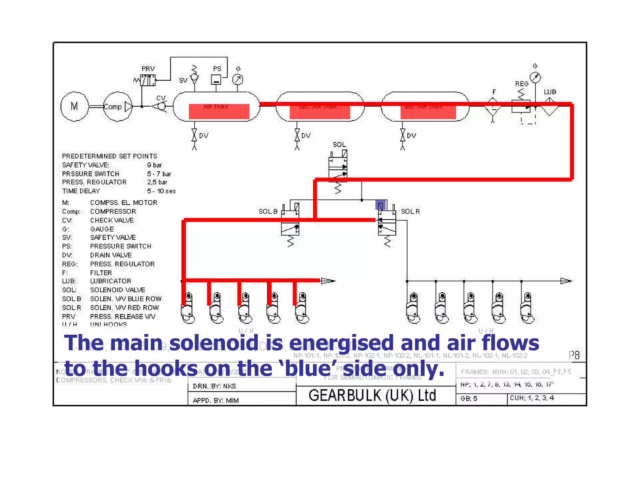
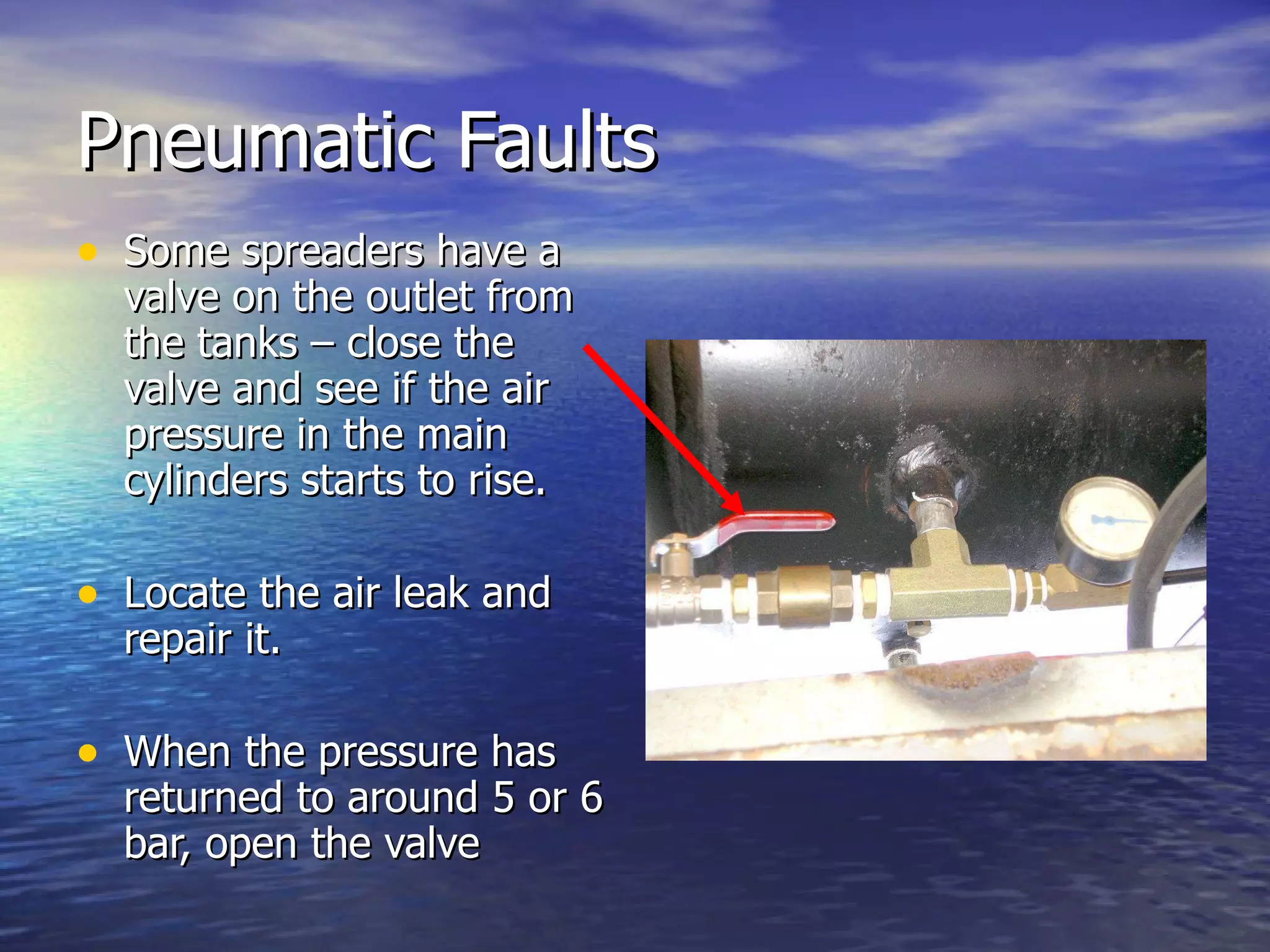
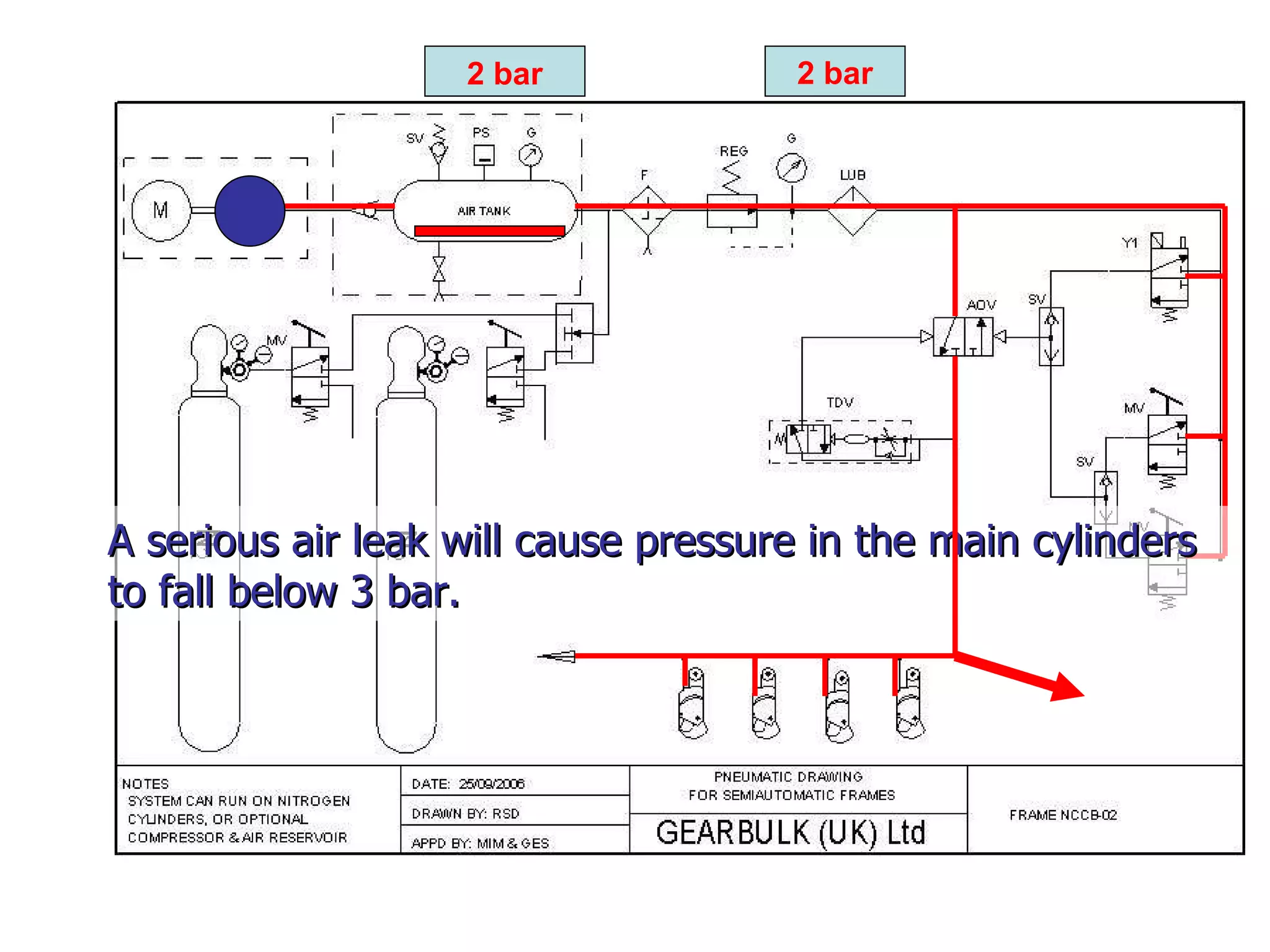
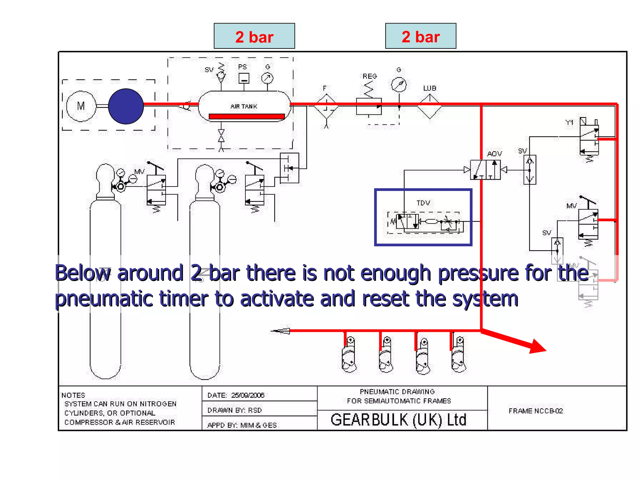
Pneumatics Pneumatic functions are very similar to electrical functions in many ways. Compressed air ‘flows’ in a similar way to electric current. Various hardware devices act like switches, or other electrical devices, to control the ‘flow’
Pressure Pressure determines the amount of force that is applied. In very simple terms, it can be considered similar to current. The higher the current, the greater the power. The higher the pressure, greater the power.
Flow Flow determines the speed of pneumatic systems. In very simple terms, it can be considered similar to dc voltage. The higher the voltage, the faster the dc machine will operate. The higher the flow, the faster the pneumatic operation.
Pneumatic Components Many simple pneumatic components can be compared to simple electrical components.
Pressure Regulator Reduces a high input pressure to a lower working pressure Provides a steady output, despite changes in the input pressure
Pressure Regulator In many ways this can be compared to a voltage regulator or zener diode.
Non-Return Valve (Check valve) Allows air to flow in one direction, but blocks it from flowing back in the opposite direction.
Non-Return Valve (Check valve) In many ways it can be compared to a diode.
Solenoid Valve When electrical current is applied to a coil, the valve operates and allows air to flow. Can be both Normally Closed (NC) or Normally Open (NO)
Solenoid Valve In many ways this can be compared to a contactor.
Shuttle Valve Allows air to flow to an outlet, from either of two inlets. Blocks air from flowing from one inlet to the other
Shuttle Valve In many ways this can be compared to a diode bridge.
Timer Has a delayed action, after receiving a compressed air signal Available in delayed-on or delayed-off formats
Timer Can be very closely compared with an electrical timer.
Air Preparation Usually consists of a filter, a regulator, a pressure gauge and a lubricator. The filter removes moisture and debris. The regulator and pressure gauge set a constant working pressure. The lubricator injects an oil mist to help lubricate the moving parts of the system.
Filter, Regulator & Lubricator
Pneumatic Operation Operation from the control cabinet in the crane For a simple pneumatic spreader
The solenoid valve energises and passes air to activate the Air Operated Valve
The Air Operated Valve allows air to flow from the main line to the hooks Even when the push-button is released and the solenoid valve de-energises
After a set delay, the timer activates and passes air to reset the Air Operated Valve The Air Operated Valve, closes, vents the line and cuts the air to the hooks
Pneumatic Operation Operation from the manual push-buttons on the side of the frame
The manual valve closes and passes air to activate the Air Operated Valve
The Air Operated Valve allows air to flow from the main line to the hooks Even when the push-button is released
After a set delay, the timer activates and passes air to reset the Air Operated Valve The Air Operated Valve, closes, vents the line and cuts the air to the hooks
Pneumatic Operation Meanwhile, the amount of air in the air tank is going down.
8 bar 3 bar
7 bar 3 bar
5 bar 3 bar
5 bar 3 bar The differential pressure switch detects the falling pressure in the air tank.
3 bar 4 bar The contacts close, which causes the compressor to start and begin to refill the air tank .
5 bar 3 bar
6 bar 3 bar
7 bar 3 bar When the air tank is topped up to full pressure, the differential pressure switch detects this.
8 bar 3 bar The contacts open, which causes the compressor to stop.
8 bar 3 bar A non-return valve between the compressor and the air tank stops air from leaking back out from the air tank.
Separate left and right release Some of the pneumatic circuit is duplicated. There are now two solenoid valves, one for releasing each side of the frame. The example shown is one of the more complex designs.
Solenoid 1 energises to release left hooks
The solenoid remains energised by an electrical timer
After a time delay, the solenoid de-energises and the air is vented.
To release the other side, solenoid 2 energises.
After a time delay, the solenoid de-energises and the air is vented.
The manual release passes air to the timer, which then activates the air-operated solenoid
When the pneumatic time delay is completed, the air signal to the air operated valve is cut.
The return spring inside the air operated valve, closes the valve & cuts the air to the hooks
“ Nagesco” Frames These frames use a slightly different operating system. All circuits operate at 110v. There are Normally Open & Normally Closed solenoid valves The release timing is via delay timers on the push-buttons.
Nagesco Frames Frame is marked with red & blue sides. Control box has a 3-position switch: Blue, ALL, Red There is a single release button (with delay-off timer)
Left & right solenoids are normally open type Main solenoid is energised and   passes air through the open solenoids to the hooks
Main solenoid is energised and   passes air through the open solenoids to the hooks
Push-button time delay expires and solenoid de-energises and vents line, causing hooks to lock
To release ‘blue’ side only, solenoid ‘R’ is energised which closes the flow to hooks on the ‘red’ side.
The main solenoid is energised and air flows to the hooks on the ‘blue’ side only.
So what can go wrong? As you can see, the electrical and pneumatic circuits are quite simple so what can go wrong with these spreaders? Well, not a lot really. The cause of most faults are air leaks or failed electro-mechanical timers.
Electrical Faults Failed compressor. Defective or wrongly adjusted pressure switch. Blown fuse or tripped circuit breaker (sometimes resulting from impact). Failed transformer Loose wiring
Electrical Faults Defective electro-mechanical timer unit. Wrong control box being used Defective gantry cable Water in power socket or damaged power socket. Damaged control socket or plug
Pneumatic Faults Defective compressor Defective or wrongly adjusted pressure regulator. Damaged pneumatic hose to hook. Defective hook (stuck or seal failure)
Pneumatic Faults Water in pneumatic system (drain tanks & check filter)
Pneumatic Faults The following is a common scenario: All hooks unlock but will not re-lock The compressor is running
Pneumatic Faults This is nearly always due to an air leak in the pneumatic system or because the release has been operated soon after the spreader was powered up.
Pneumatic Faults Check the air pressure on the main air cylinders. Is it less than 3 bar? If yes, then you probably have a large air-leak. The air is leaking out as fast as the compressor tries to fill the tanks.
Pneumatic Faults Some spreaders have a valve on the outlet from the tanks – close the valve and see if the air pressure in the main cylinders starts to rise. Locate the air leak and repair it. When the pressure has returned to around 5 or 6 bar, open the valve
Pneumatic Faults If there is no valve on the outlet of the main air cylinders- Remove power to the spreader. Repair the air leak Restore power to the spreader. Wait for the pressure in the main cylinders to rise to around 5-6 bar.
2 bar 2 bar A serious air leak will cause pressure in the main cylinders to fall below 3 bar.
2 bar 2 bar Below around 2 bar there is not enough pressure for the pneumatic timer to activate and reset the system
2 bar 2 bar Therefore the hooks will remain open and the leak will prevent the cylinder pressure from rising, despite the operation of the compressor

Pneumatics

  • 1.
    Pneumatics Pneumatic functionsare very similar to electrical functions in many ways. Compressed air ‘flows’ in a similar way to electric current. Various hardware devices act like switches, or other electrical devices, to control the ‘flow’
  • 2.
    Pressure Pressure determinesthe amount of force that is applied. In very simple terms, it can be considered similar to current. The higher the current, the greater the power. The higher the pressure, greater the power.
  • 3.
    Flow Flow determinesthe speed of pneumatic systems. In very simple terms, it can be considered similar to dc voltage. The higher the voltage, the faster the dc machine will operate. The higher the flow, the faster the pneumatic operation.
  • 4.
    Pneumatic Components Manysimple pneumatic components can be compared to simple electrical components.
  • 5.
    Pressure Regulator Reducesa high input pressure to a lower working pressure Provides a steady output, despite changes in the input pressure
  • 6.
    Pressure Regulator Inmany ways this can be compared to a voltage regulator or zener diode.
  • 7.
    Non-Return Valve (Checkvalve) Allows air to flow in one direction, but blocks it from flowing back in the opposite direction.
  • 8.
    Non-Return Valve (Checkvalve) In many ways it can be compared to a diode.
  • 9.
    Solenoid Valve Whenelectrical current is applied to a coil, the valve operates and allows air to flow. Can be both Normally Closed (NC) or Normally Open (NO)
  • 10.
    Solenoid Valve Inmany ways this can be compared to a contactor.
  • 11.
    Shuttle Valve Allowsair to flow to an outlet, from either of two inlets. Blocks air from flowing from one inlet to the other
  • 12.
    Shuttle Valve Inmany ways this can be compared to a diode bridge.
  • 13.
    Timer Has adelayed action, after receiving a compressed air signal Available in delayed-on or delayed-off formats
  • 14.
    Timer Can bevery closely compared with an electrical timer.
  • 15.
    Air Preparation Usuallyconsists of a filter, a regulator, a pressure gauge and a lubricator. The filter removes moisture and debris. The regulator and pressure gauge set a constant working pressure. The lubricator injects an oil mist to help lubricate the moving parts of the system.
  • 16.
  • 17.
    Pneumatic Operation Operationfrom the control cabinet in the crane For a simple pneumatic spreader
  • 18.
    The solenoid valveenergises and passes air to activate the Air Operated Valve
  • 19.
    The Air OperatedValve allows air to flow from the main line to the hooks Even when the push-button is released and the solenoid valve de-energises
  • 20.
    After a setdelay, the timer activates and passes air to reset the Air Operated Valve The Air Operated Valve, closes, vents the line and cuts the air to the hooks
  • 21.
    Pneumatic Operation Operationfrom the manual push-buttons on the side of the frame
  • 22.
    The manual valvecloses and passes air to activate the Air Operated Valve
  • 23.
    The Air OperatedValve allows air to flow from the main line to the hooks Even when the push-button is released
  • 24.
    After a setdelay, the timer activates and passes air to reset the Air Operated Valve The Air Operated Valve, closes, vents the line and cuts the air to the hooks
  • 25.
    Pneumatic Operation Meanwhile,the amount of air in the air tank is going down.
  • 26.
  • 27.
  • 28.
  • 29.
    5 bar 3bar The differential pressure switch detects the falling pressure in the air tank.
  • 30.
    3 bar 4bar The contacts close, which causes the compressor to start and begin to refill the air tank .
  • 31.
  • 32.
  • 33.
    7 bar 3bar When the air tank is topped up to full pressure, the differential pressure switch detects this.
  • 34.
    8 bar 3bar The contacts open, which causes the compressor to stop.
  • 35.
    8 bar 3bar A non-return valve between the compressor and the air tank stops air from leaking back out from the air tank.
  • 36.
    Separate left andright release Some of the pneumatic circuit is duplicated. There are now two solenoid valves, one for releasing each side of the frame. The example shown is one of the more complex designs.
  • 37.
    Solenoid 1 energisesto release left hooks
  • 38.
    The solenoid remainsenergised by an electrical timer
  • 39.
    After a timedelay, the solenoid de-energises and the air is vented.
  • 40.
    To release theother side, solenoid 2 energises.
  • 41.
    After a timedelay, the solenoid de-energises and the air is vented.
  • 42.
    The manual releasepasses air to the timer, which then activates the air-operated solenoid
  • 43.
    When the pneumatictime delay is completed, the air signal to the air operated valve is cut.
  • 44.
    The return springinside the air operated valve, closes the valve & cuts the air to the hooks
  • 45.
    “ Nagesco” FramesThese frames use a slightly different operating system. All circuits operate at 110v. There are Normally Open & Normally Closed solenoid valves The release timing is via delay timers on the push-buttons.
  • 46.
    Nagesco Frames Frameis marked with red & blue sides. Control box has a 3-position switch: Blue, ALL, Red There is a single release button (with delay-off timer)
  • 47.
    Left & rightsolenoids are normally open type Main solenoid is energised and passes air through the open solenoids to the hooks
  • 48.
    Main solenoid isenergised and passes air through the open solenoids to the hooks
  • 49.
    Push-button time delayexpires and solenoid de-energises and vents line, causing hooks to lock
  • 50.
    Push-button time delayexpires and solenoid de-energises and vents line, causing hooks to lock
  • 51.
    To release ‘blue’side only, solenoid ‘R’ is energised which closes the flow to hooks on the ‘red’ side.
  • 52.
    The main solenoidis energised and air flows to the hooks on the ‘blue’ side only.
  • 53.
    So what cango wrong? As you can see, the electrical and pneumatic circuits are quite simple so what can go wrong with these spreaders? Well, not a lot really. The cause of most faults are air leaks or failed electro-mechanical timers.
  • 54.
    Electrical Faults Failedcompressor. Defective or wrongly adjusted pressure switch. Blown fuse or tripped circuit breaker (sometimes resulting from impact). Failed transformer Loose wiring
  • 55.
    Electrical Faults Defectiveelectro-mechanical timer unit. Wrong control box being used Defective gantry cable Water in power socket or damaged power socket. Damaged control socket or plug
  • 56.
    Pneumatic Faults Defectivecompressor Defective or wrongly adjusted pressure regulator. Damaged pneumatic hose to hook. Defective hook (stuck or seal failure)
  • 57.
    Pneumatic Faults Waterin pneumatic system (drain tanks & check filter)
  • 58.
    Pneumatic Faults Thefollowing is a common scenario: All hooks unlock but will not re-lock The compressor is running
  • 59.
    Pneumatic Faults Thisis nearly always due to an air leak in the pneumatic system or because the release has been operated soon after the spreader was powered up.
  • 60.
    Pneumatic Faults Checkthe air pressure on the main air cylinders. Is it less than 3 bar? If yes, then you probably have a large air-leak. The air is leaking out as fast as the compressor tries to fill the tanks.
  • 61.
    Pneumatic Faults Somespreaders have a valve on the outlet from the tanks – close the valve and see if the air pressure in the main cylinders starts to rise. Locate the air leak and repair it. When the pressure has returned to around 5 or 6 bar, open the valve
  • 62.
    Pneumatic Faults Ifthere is no valve on the outlet of the main air cylinders- Remove power to the spreader. Repair the air leak Restore power to the spreader. Wait for the pressure in the main cylinders to rise to around 5-6 bar.
  • 63.
    2 bar 2bar A serious air leak will cause pressure in the main cylinders to fall below 3 bar.
  • 64.
    2 bar 2bar Below around 2 bar there is not enough pressure for the pneumatic timer to activate and reset the system
  • 65.
    2 bar 2bar Therefore the hooks will remain open and the leak will prevent the cylinder pressure from rising, despite the operation of the compressor