Cont…………………………………….
(iii) Simple design
•The designs of pneumatic components are relatively simple. They are
thus more suitable for use in simple automatic control systems.
(iv)High adaptability to harsh environment
• Compared to the elements of other systems, compressed air is less
affected by high temperature, dust, corrosion, etc.
(v) Safety
• Pneumatic systems are safer than electromotive systems because they
can work in inflammable environment without causing fire or explosion.
Apart from that, overloading in pneumatic system will only lead to
sliding or cessation of operation. Unlike electromotive components,
pneumatic components do not burn or get overheated when
overloaded.
3.
Cont…………………………………..
(vi) Easy selectionof speed and pressure
• The speeds of rectilinear and oscillating movement of pneumatic systems are
easy to adjust and subject to few limitations. The pressure and the volume of
air can easily be adjusted by a pressure regulator.
(vii) Environmental friendly
• The operation of pneumatic systems does not produce pollutants. The air
released is also processed in special ways. Therefore, pneumatic systems can
work in environments that demand high level of cleanliness. One example is
the production lines of integrated circuits.
(viii) Economical
• As pneumatic components are not expensive, the costs of pneumatic systems
are quite low.
• Moreover, as pneumatic systems are very durable, the cost of repair is
significantly lower than that of other systems
4.
(b) Limitations ofpneumatic systems
• Although pneumatic systems possess a lot of
advantages, they are also subject to many limitations.
(i) Relatively low accuracy
• As pneumatic systems are powered by the force
provided by compressed air, their operation is subject
to the volume of the compressed air. As the volume of
air may change when compressed or heated, the
supply of air to the system may not be accurate,
causing a decrease in the overall accuracy of the
system.
5.
cont………………………………..
(ii) Low loading
•As the cylinders of pneumatic components are not very large, a pneumatic
system cannot drive loads that are too heavy.
(iii) Processing required before use
• Compressed air must be processed before use to ensure the absence of water
vapour or dust.
• Otherwise, the moving parts of the pneumatic components may wear out
quickly due to friction.
(iv) Uneven moving speed
• As air can easily be compressed, the moving speeds of the pistons are relatively
uneven.
(v) Noise
• Noise will be produced when compressed air is released from the pneumatic
components.
6.
(c) Main pneumaticcomponents
• Pneumatic components can be divided into two categories:
1. Components that produce and transport compressed air.
2. Components that consume compressed air.
• All main pneumatic components can be represented by
simple pneumatic symbols. Each symbol shows only the
function of the component it represents, but not its
structure. Pneumatic symbols can be combined to form
pneumatic diagrams. A pneumatic diagram describes the
relations between each pneumatic component, that is, the
design of the system.
7.
1 The productionand transportation of compressed air
• Examples of components that produce and transport
compressed air include compressors and pressure regulating
components.
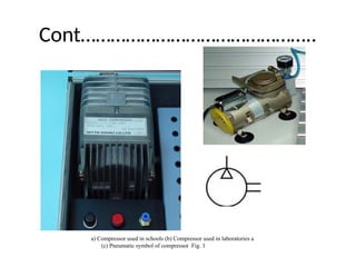
(a) Compressor
• A compressor can compress air to the required pressures. It
can convert the mechanical energy from motors and engines
into the potential energy in compressed air (Fig. 2). A single
central compressor can supply various pneumatic components
with compressed air, which is transported through pipes from
the cylinder to the pneumatic components. Compressors can
be divided into two classes: reciprocatory and rotary.
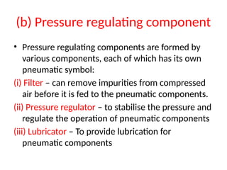
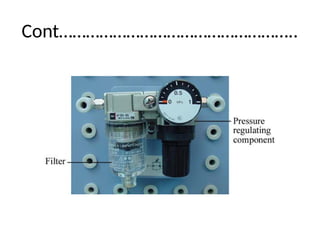
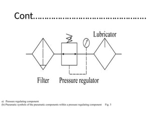
(b) Pressure regulatingcomponent
• Pressure regulating components are formed by
various components, each of which has its own
pneumatic symbol:
(i) Filter – can remove impurities from compressed
air before it is fed to the pneumatic components.
(ii) Pressure regulator – to stabilise the pressure and
regulate the operation of pneumatic components
(iii) Lubricator – To provide lubrication for
pneumatic components
3 The consumptionof compressed air
• Examples of components that consume compressed air
include execution components (cylinders), directional
control valves and assistant valves.
(a) Execution component
• Pneumatic execution components provide rectilinear or
rotary movement. Examples of pneumatic execution
components include cylinder pistons, pneumatic motors,
etc. Rectilinear motion is produced by cylinder pistons,
while pneumatic motors provide continuous rotations.
• There are many kinds of cylinders, such as single acting
cylinders and double acting
13.
Cont……………………………………………
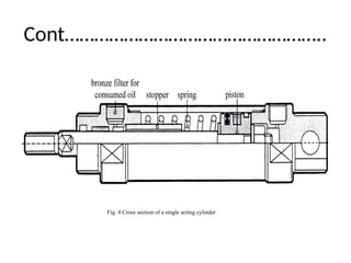
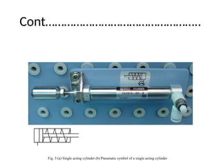
(i) Single actingcylinder
• A single acting cylinder has only one entrance
that allows compressed air to flow through.
• Therefore, it can only produce thrust in one
direction (Fig. 4). The piston rod is propelled in
the opposite direction by an internal spring, or
by the external force provided by mechanical
movement or weight of a load (Fig. 5).
Cont……………………………………………
• The thrustfrom the piston rod is greatly lowered
because it has to overcome the force from the
spring. Therefore, in order to provide the driving
force for machines, the diameter of the cylinder
should be increased. In order to match the length
of the spring, the length of the cylinder should also
be increased, thus limiting the length of the path.
• Single acting cylinders are used in stamping,
printing, moving materials, etc.
17.
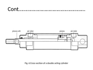
(ii) Double actingcylinder
• In a double acting cylinder, air pressure is applied
alternately to the relative surface of the piston,
producing a propelling force and a retracting
force (Fig. 6). As the effective area of the piston is
small, the thrust produced during retraction is
relatively weak. The impeccable tubes of double
acting cylinders are usually made of steel. The
working surfaces are also polished and coated
with chromium to reduce friction.
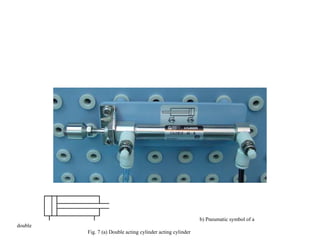
b) Pneumatic symbolof a
double
Fig. 7 (a) Double acting cylinder acting cylinder
20.
(b) Directional controlvalve
• Directional control valves ensure the flow of air between
air ports by opening, closing and switching their internal
connections. Their classification is determined by the
number of ports, the number of switching positions, the
normal position of the valve and its method of operation.
• Common types of directional control valves include 2/2,
3/2, 5/2, etc. The first number represents the number of
ports; the second number represents the number of
positions. A directional control valve that has two ports
and five positions can be represented by the drawing in
Fig. 8, as well as its own unique pneumatic symbol.
21.
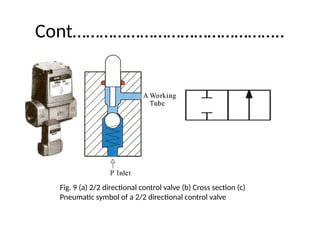
(i) 2/2 Directionalcontrol valve (shut-off
valve )
• The structure of a 2/2 directional control valve is very
simple. It uses the thrust from the spring to open and
close the valve, stopping compressed air from flowing
towards working tube ‘A’ from air inlet ‘P’. When a force
is applied to the control axis, the valve will be pushed
open, connecting ‘P’ with ‘A’ (Fig. 9).
• The force applied to the control axis has to overcome
both air pressure and the repulsive force of the spring.
The control valve can be driven manually or mechanically,
and restored to its original position by the spring.
22.
Cont………………………………………..
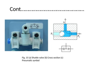
Fig. 9 (a)2/2 directional control valve (b) Cross section (c)
Pneumatic symbol of a 2/2 directional control valve
23.
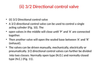
(ii) 3/2 Directionalcontrol valve
• (ii) 3/2 Directional control valve
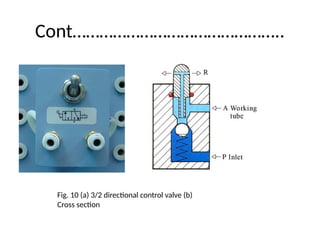
• A 3/2 directional control valve can be used to control a single
acting cylinder (Fig. 10). The
• open valves in the middle will close until ‘P’ and ‘A’ are connected
together.
• Then another valve will open the sealed base between ‘A’ and ‘R’
(exhaust).
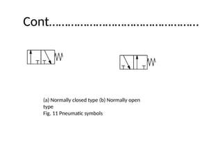
• The valves can be driven manually, mechanically, electrically or
pneumatically. 3/2 directional control valves can further be divided
into two classes: Normally open type (N.O.) and normally closed
type (N.C.) (Fig. 11).
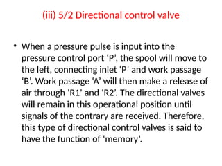
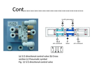
(iii) 5/2 Directionalcontrol valve
• When a pressure pulse is input into the
pressure control port ‘P’, the spool will move to
the left, connecting inlet ‘P’ and work passage
‘B’. Work passage ‘A’ will then make a release of
air through ‘R1’ and ‘R2’. The directional valves
will remain in this operational position until
signals of the contrary are received. Therefore,
this type of directional control valves is said to
have the function of ‘memory’.
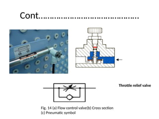
(c) Control valve
•A control valve is a valve that controls the flow of air.
Examples include non-return valves, flow control
valves, shuttle valves, etc.
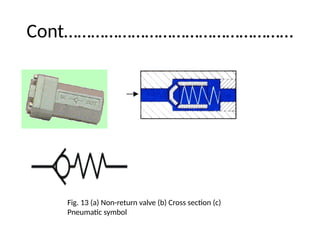
• (i) Non-return valve
• A non-return valve allows air to flow in one direction
only. When air flows in the opposite direction, the
valve will close.
• Another name for non-return valve is poppet valve
(Fig. 13).
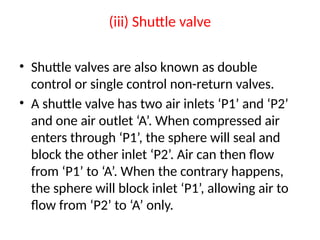
(iii) Shuttle valve
•Shuttle valves are also known as double
control or single control non-return valves.
• A shuttle valve has two air inlets ‘P1’ and ‘P2’
and one air outlet ‘A’. When compressed air
enters through ‘P1’, the sphere will seal and
block the other inlet ‘P2’. Air can then flow
from ‘P1’ to ‘A’. When the contrary happens,
the sphere will block inlet ‘P1’, allowing air to
flow from ‘P2’ to ‘A’ only.
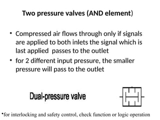
Two pressure valves(AND element)
• Compressed air flows through only if signals
are applied to both inlets the signal which is
last applied passes to the outlet
• for 2 different input pressure, the smaller
pressure will pass to the outlet
•for interlocking and safety control, check function or logic operation
39.
4. Principles ofpneumatic control
• (a) Pneumatic circuit
• Pneumatic control systems can be designed in the
form of pneumatic circuits. A pneumatic
• circuit is formed by various pneumatic components,
such as cylinders, directional control valves, flow
control valves, etc. Pneumatic circuits have the
following functions:
• 1. To control the injection and release of compressed
air in the cylinders.
• 2. To use one valve to control another valve.
40.
(b) Pneumatic circuitdiagram
• A pneumatic circuit diagram uses pneumatic
symbols to describe its design. Some basic
rules
• must be followed when drawing pneumatic
diagrams.
41.
(i) Basic rules
1.A pneumatic circuit diagram represents the circuit in static
form and assumes there is no supply of pressure. The
placement of the pneumatic components on the circuit also
follows this assumption.
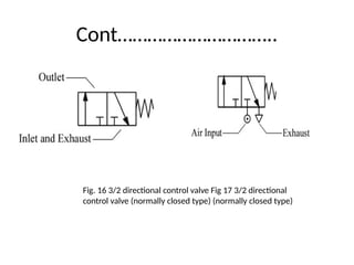
2. The pneumatic symbol of a directional control valve is formed
by one or more squares. The inlet and exhaust are drawn
underneath the square, while the outlet is drawn on the top.
• Each function of the valve (the position of the valve) shall be
represented by a square. If there are two or more functions,
the squares should be arranged horizontally (Fig. 16).
42.
Cont…………………………..
Fig. 16 3/2directional control valve Fig 17 3/2 directional
control valve (normally closed type) (normally closed type)
43.
Cont………………………………………..
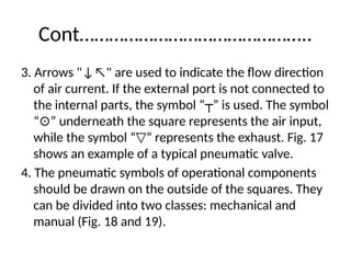
3. Arrows "↓↖"are used to indicate the flow direction
of air current. If the external port is not connected to
the internal parts, the symbol “ ” is used. The symbol
┬
“ ” underneath the square represents the air input,
⊙
while the symbol “ ” represents the exhaust. Fig. 17
▽
shows an example of a typical pneumatic valve.
4. The pneumatic symbols of operational components
should be drawn on the outside of the squares. They
can be divided into two classes: mechanical and
manual (Fig. 18 and 19).
44.
Cont………………………………………….
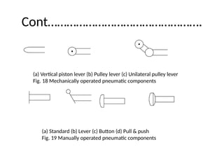
(a) Vertical pistonlever (b) Pulley lever (c) Unilateral pulley lever
Fig. 18 Mechanically operated pneumatic components
(a) Standard (b) Lever (c) Button (d) Pull & push
Fig. 19 Manually operated pneumatic components
45.
Cont…………………………………………….
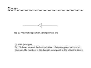
5. Pneumatic operationsignal pressure lines
should be drawn on one side of the squares,
while triangles are used to represent the
direction of air flow (Fig. 20).
46.
Cont……………………………………………
Fig. 20 Pneumaticoperation signal pressure line
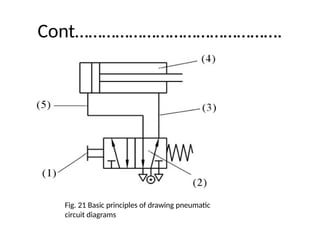
(ii) Basic principles
Fig. 21 shows some of the basic principles of drawing pneumatic circuit
diagrams, the numbers in the diagram correspond to the following points:
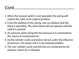
Cont………………………………………………
1. When themanual switch is not operated, the spring will
restore the valve to its original position.
2. From the position of the spring, one can deduce that the
block is operating. The other block will not operate until the
switch is pushed.
3. Air pressure exists along this line because it is connected to
the source of compressed air.
4. As this cylinder cavity and piston rod are under the influence
of pressure, the piston rod is in its restored position.
5. The rear cylinder cavity and this line are connected to the
exhaust, where air is released.
49.
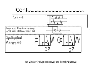
(iii) The settingof circuit diagrams
• When drawing a complete circuit diagram, one
should place the pneumatic components on
different levels and positions, so the relations
between the components can be expressed
clearly.
• This is called the setting of circuit diagrams. A
circuit diagram is usually divided into three
levels: power level, logic level and signal input
level (Fig. 22).
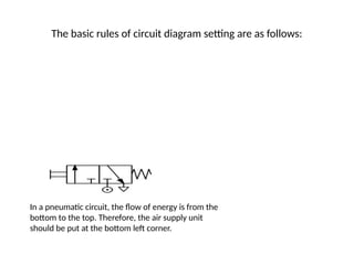
The basic rulesof circuit diagram setting are as follows:
In a pneumatic circuit, the flow of energy is from the
bottom to the top. Therefore, the air supply unit
should be put at the bottom left corner.
52.
Cont………………………………..
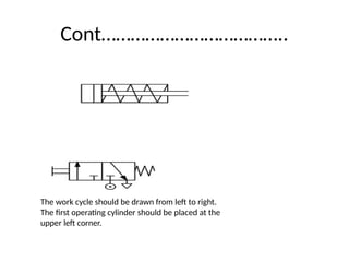
The work cycleshould be drawn from left to right.
The first operating cylinder should be placed at the
upper left corner.
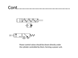
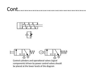
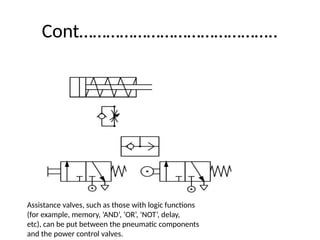
Cont……………………………………..
Assistance valves, suchas those with logic functions
(for example, memory, ‘AND’, ‘OR’, ‘NOT’, delay,
etc), can be put between the pneumatic components
and the power control valves.
56.
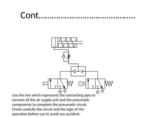
Cont……………………………………..
Use the linewhich represents the connecting pipe to
connect all the air supply unit and the pneumatic
components to complete the pneumatic circuit.
Check carefully the circuit and the logic of the
operation before use to avoid any accident.
57.
5 Different kindsof basic circuits
• A basic circuit is a pneumatic circuit designed
to perform basic tasks, such as flow
amplification, signal inversion, memory, delay,
single acting cylinder control, double acting
cylinder control, etc.
58.
(a) Flow amplification
•Cylinders with a large capacity require a larger flow of air, which
can be hazardous to users. It is unsafe to manually operate
pneumatic directional control valves with large flow capacity.
Instead we should first operate manually a small control valve
and use it to operate the pneumatic control system with large
flow capacity. This is called flow amplification, which can greatly
ensure the safety of the operators. During operation, valves
with large flow capacity should be placed near the cylinder,
while valves with smaller flow capacity should be placed on
control boards some distances away. Fig. 23 shows a basic flow
amplification circuit. Notice how different components are
placed on different levels.
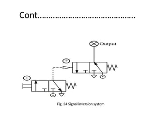
(b) Signal inversion
•The pneumatic diagram in Fig. 24 shows how
directional control valves can be switched.
When operating control valve , control valve
will stop producing pressure output. When
control valve ceases operation and is
restored to its original position, control valve
will resume its output. Therefore, at any given
time, the pressure output of control valve is
the exact opposite of that of control valve .
Cont…………………………………………….
• 17
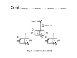
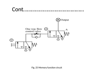
• (c) Memory Function
• Memory is a common basic function. It can keep a component at a
certain state
• permanently until there is a change of signals. Fig. 25 shows a memory
function circuit. When
• control valve is operated momentarily (that is, pressed for a short
time), the output signal of the
• 5/2 directional control valve will be set to ON. The signal will stay that
way until control valve
• is operated momentarily and generates another signal to replace it,
causing it to stay permanently
• at OFF.
(d) Delay function
•A pneumatic delay circuit can delay the
operating time of the next control valve. Its
principle of operation involves the use of an
orifice to slow down the flow of air and
control the time of pneumatic operation.
Delay functions can be divided into two
classes: ON-signal delay and OFF signal delay.
65.
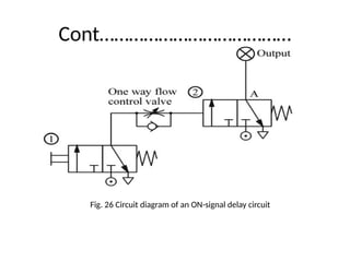
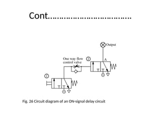
(i) ON-signal delay
•Fig. 26 shows the circuit diagram of an ON-
signal delay circuit, which delays the output of
the next control valve. When control valve
is operated, the one way flow control valve
will slow down the flow of air, thus delaying
the signal output of the outlet of control valve
(A), resulting in a persistent ON-signal. The
time when control valve will be restored to
its original position is not affected.
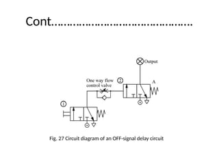
(ii) OFF-signal Delay
•Fig. 27 shows the circuit diagram of an OFF-signal delay circuit,
which delays the output of
• the next control valve. This circuit is similar to an ON-signal
delay circuit. The only difference is
• that the one way flow control valve is connected in the
opposite direction. Therefore, when control
• valve is operated, the outlet of control valve (A) will
continue to output signals. However,
• when control valve is restored to its original position, the
release of air is slowed down by the
• one way flow control valve, resulting in a persistent OFF-signal.
(d) Delay function
•A pneumatic delay circuit can delay the
operating time of the next control valve. Its
principle of operation involves the use of an
orifice to slow down the flow of air and
control the time of pneumatic operation.
Delay functions can be divided into two
classes: ON-signal delay and OFF signal delay.
70.
(i) ON-signal delay
•Fig. 26 shows the circuit diagram of an ON-
signal delay circuit, which delays the output of
the next control valve. When control valve
is operated, the one way flow control valve
will slow down the flow of air, thus delaying
the signal output of the outlet of control valve
(A), resulting in a persistent ON-signal. The
time when control valve will be restored to
its original position is not affected.
(ii) OFF-signal Delay
•Fig. 27 shows the circuit diagram of an OFF-signal delay
circuit, which delays the output of the next control
valve. This circuit is similar to an ON-signal delay circuit.
The only difference is that the one way flow control
valve is connected in the opposite direction. Therefore,
when control valve is operated, the outlet of control
valve (A) will continue to output signals. However,
when control valve is restored to its original position,
the release of air is slowed down by the one way flow
control valve, resulting in a persistent OFF-signal.
(e) Single actingcylinder control
• Single acting cylinders can be controlled
manually. However, they can also be
controlled by two or more valves. This is called
logic control. Examples of logic control include
‘OR’ function, ‘AND’ function, ‘NOT’ function,
etc.
75.
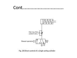
(i) Direct controland speed control
• If a single acting cylinder is connected to a
manual 3/2 directional control valve, when
the control valve is operated, it will cause the
cylinder to work (Fig. 28). Therefore, the
circuit allows the cylinder to be controlled
manually.
Cont……………………………………………
• The onlyway to change the extension speed
of the piston of a single acting cylinder is to
restrict the flow of air at the inlet and use the
spring to determine the speed of retraction.
Therefore, a one way flow control valve is
placed in the circuit to control the speed.
78.
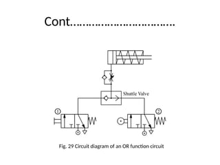
(ii) OR Function
•The single acting cylinder in Fig. 29 can be operated by
two different circuits. Examples include manual operation
and relying on automatic circuit signals, that is, when
either control valve 1 or control valve 2 is operated, the
cylinder will work. Therefore, the circuit in Fig. 29
possesses the OR function. However, if the output of two
3/2 directional control valves are connected through the
port of a triode, the air current from control valve 1 will
be released through the exhaust of control valve 2, and
so the cylinder will not work. This problem can be solved
by connecting a shuttle valve to the port of the triode.
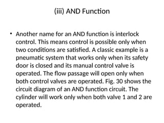
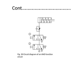
(iii) AND Function
•Another name for an AND function is interlock
control. This means control is possible only when
two conditions are satisfied. A classic example is a
pneumatic system that works only when its safety
door is closed and its manual control valve is
operated. The flow passage will open only when
both control valves are operated. Fig. 30 shows the
circuit diagram of an AND function circuit. The
cylinder will work only when both valve 1 and 2 are
operated.
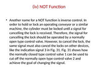
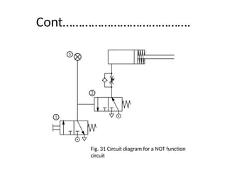
(iv) NOT Function
•Another name for a NOT function is inverse control. In
order to hold or lock an operating conveyor or a similar
machine, the cylinder must be locked until a signal for
cancelling the lock is received. Therefore, the signal for
cancelling the lock should be operated by a normally
open type control valve. However, to cancel the lock, the
same signal must also cancel the locks on other devices,
like the indication signal 3 in Fig. 31. Fig. 31 shows how
the normally closed type control valve 1 can be used to
cut off the normally open type control valve 2 and
achieve the goal of changing the signal.