Downloaded 10 times

![4/1/2016 Sanjay Humania [M.Tech - Mechatronics] 29](https://image.slidesharecdn.com/1b-210323030110/85/1-b-pneumatic-components-29-320.jpg)
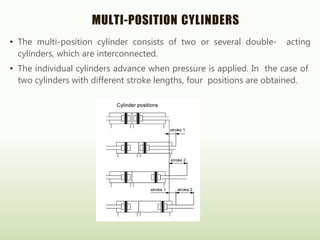
![LOGICS
4/1/2016 Sanjay Humania [M.Tech - Mechatronics] 45
• AND logic
• OR logic
• NOT logic
• NAND logic
• NOR logic
• EX-OR logic](https://image.slidesharecdn.com/1b-210323030110/85/1-b-pneumatic-components-45-320.jpg)
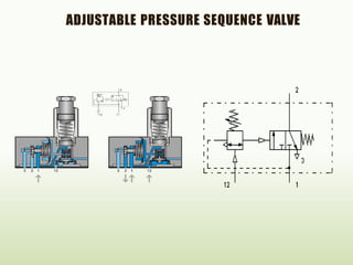

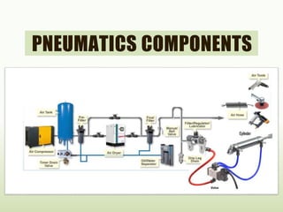
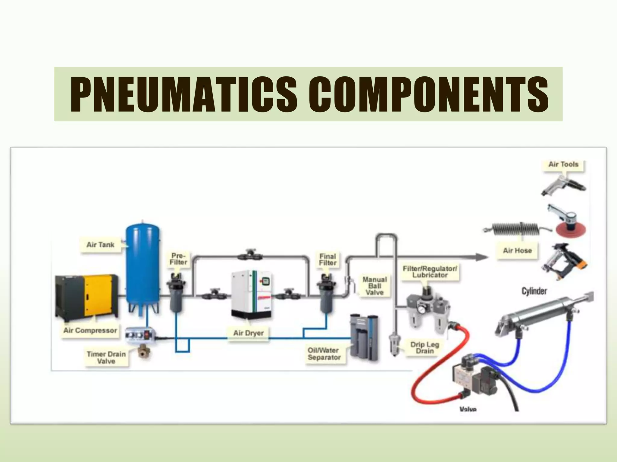
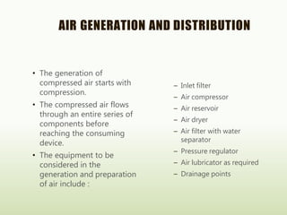
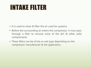
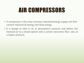
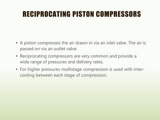
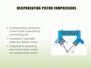
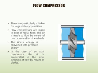
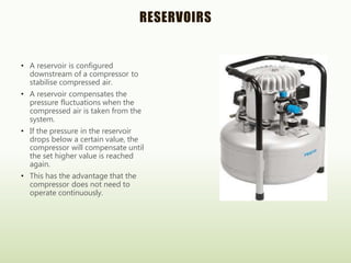
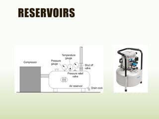
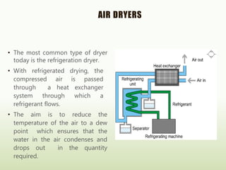
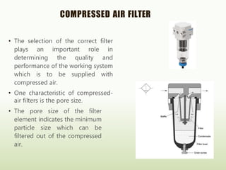
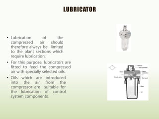
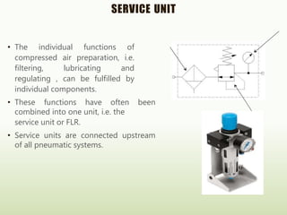
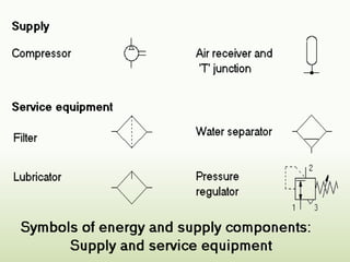
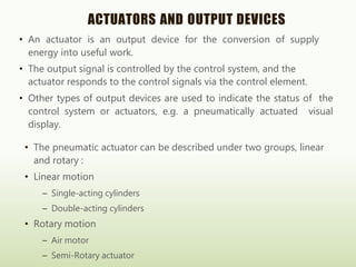
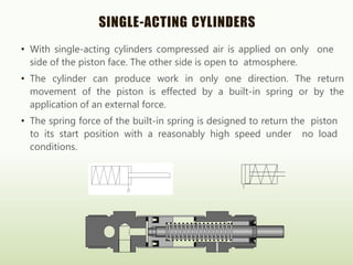
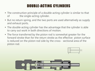
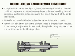
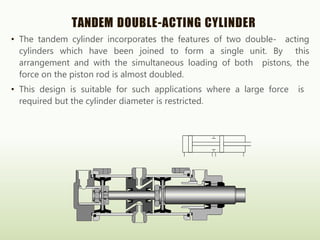
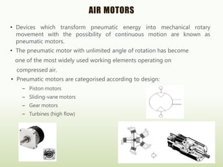
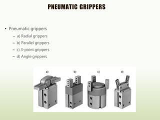
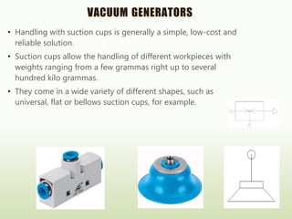
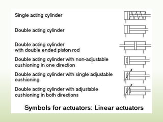
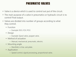
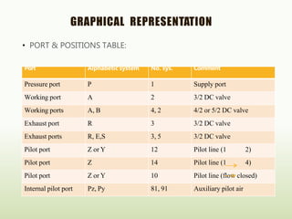
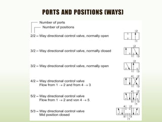
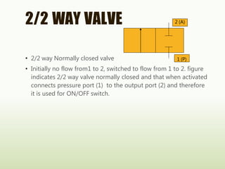
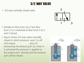
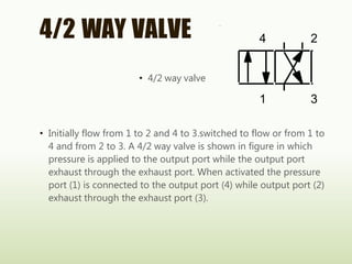
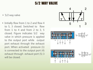
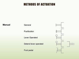
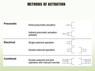
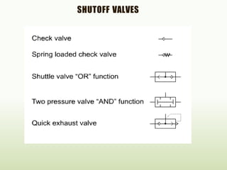
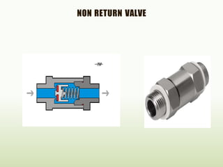
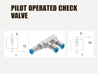
The document discusses pneumatics components used in automation systems. It describes the process of compressed air generation including air compression, filtering, drying and storage. It also discusses various pneumatic actuators and output devices like cylinders, grippers, and motors that convert compressed air into mechanical motion or force. Valves are described as key components to control pneumatic circuits and air flow. Common types include 2/2 way, 3/2 way, and 5/2 way valves along with methods of actuation.


![SBP- Air compressor [Compatibility Mode].pdf](https://cdn.slidesharecdn.com/ss_thumbnails/sbp-aircompressorcompatibilitymode-241227102120-b6a67cde-thumbnail.jpg?width=640&height=640&fit=bounds)


