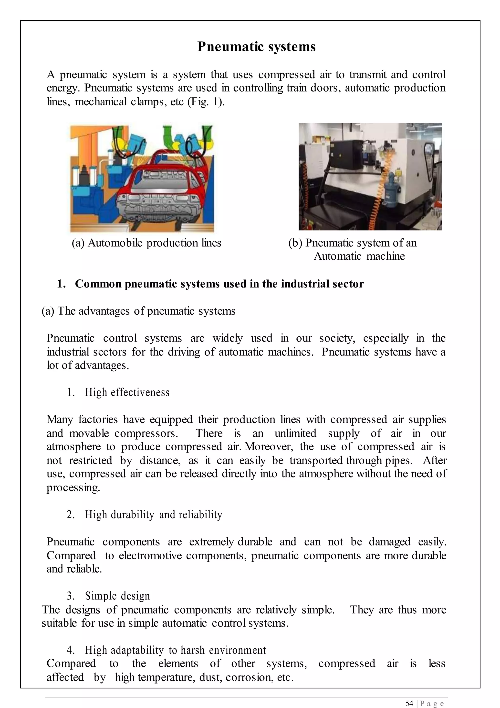
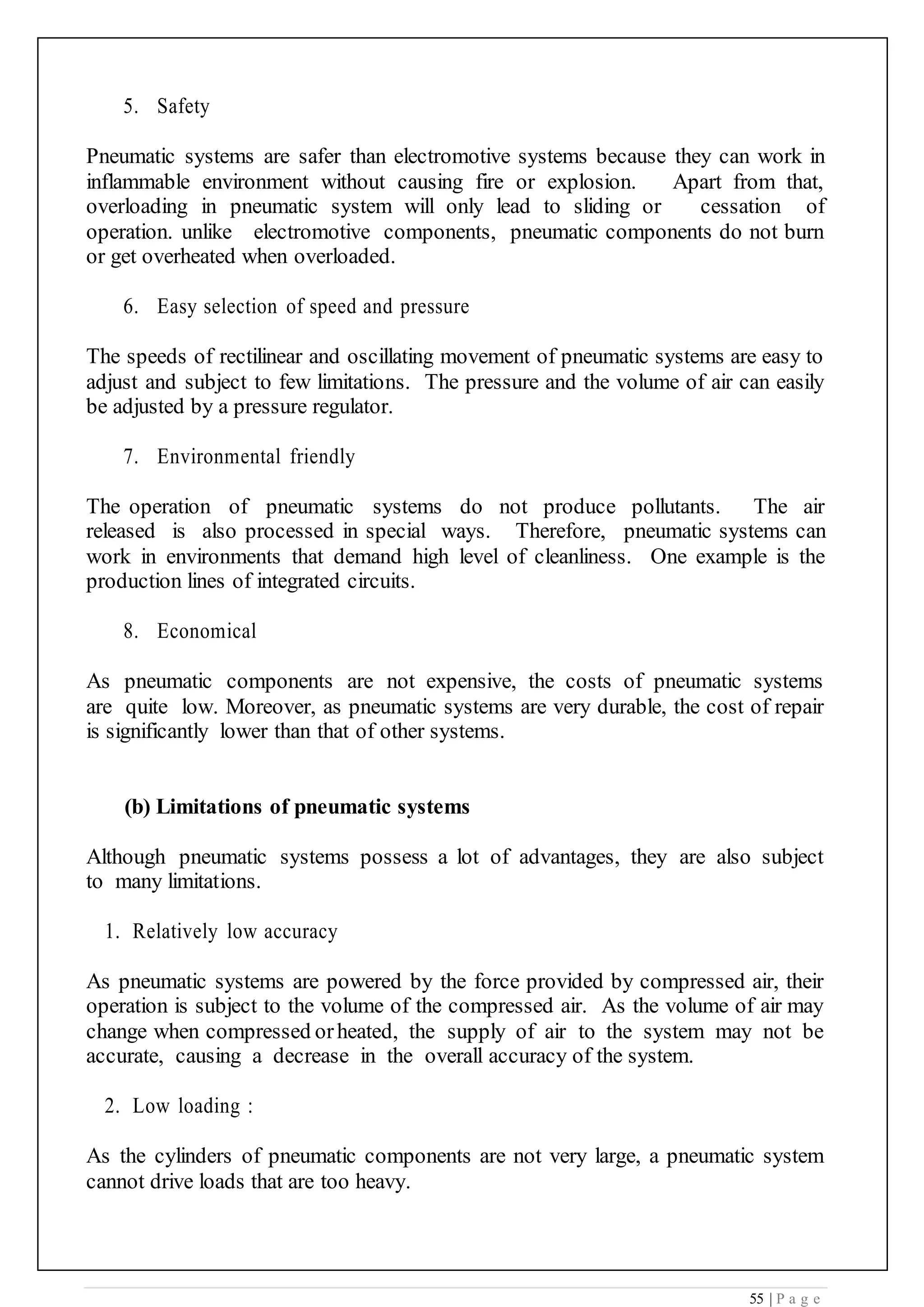
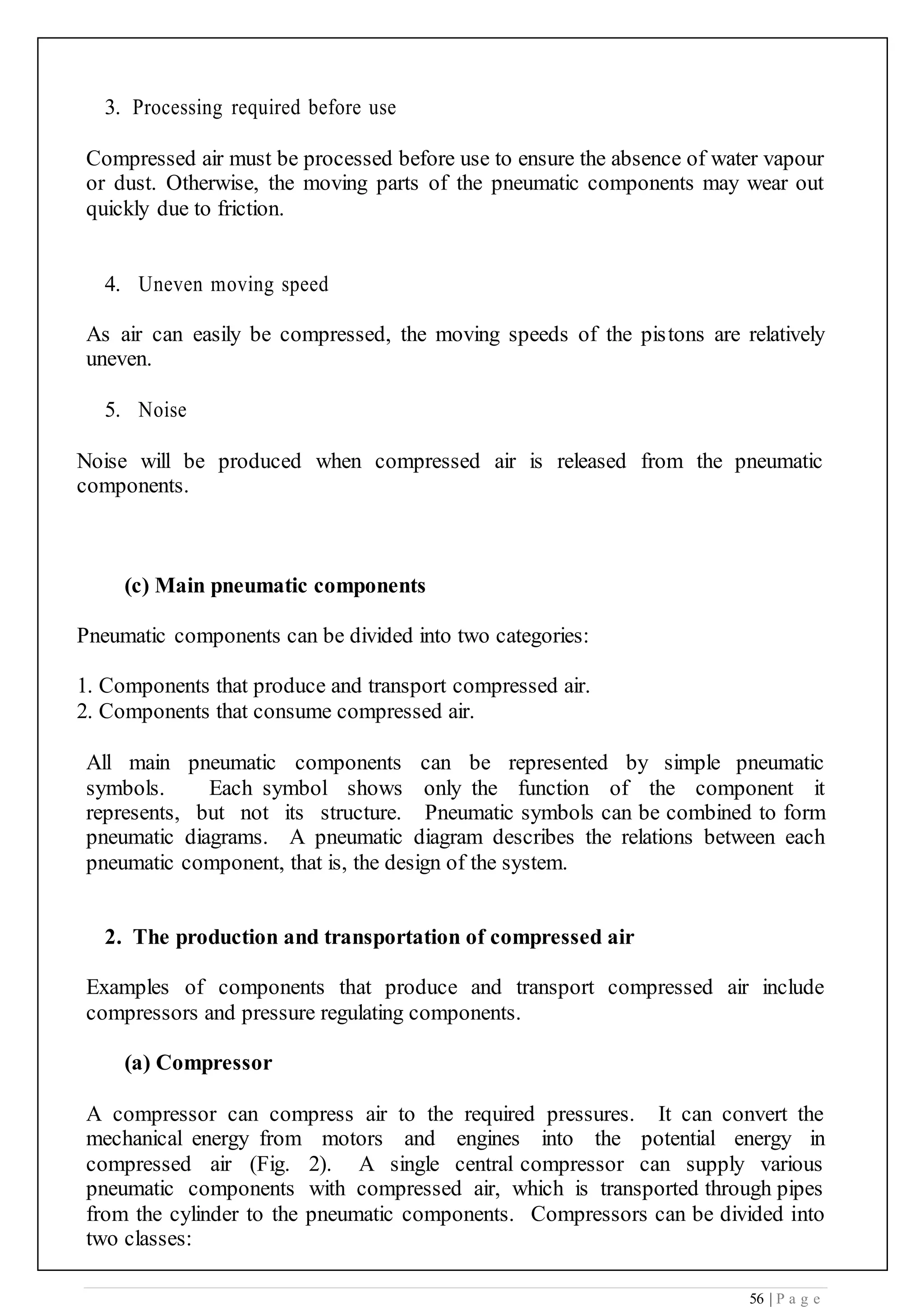
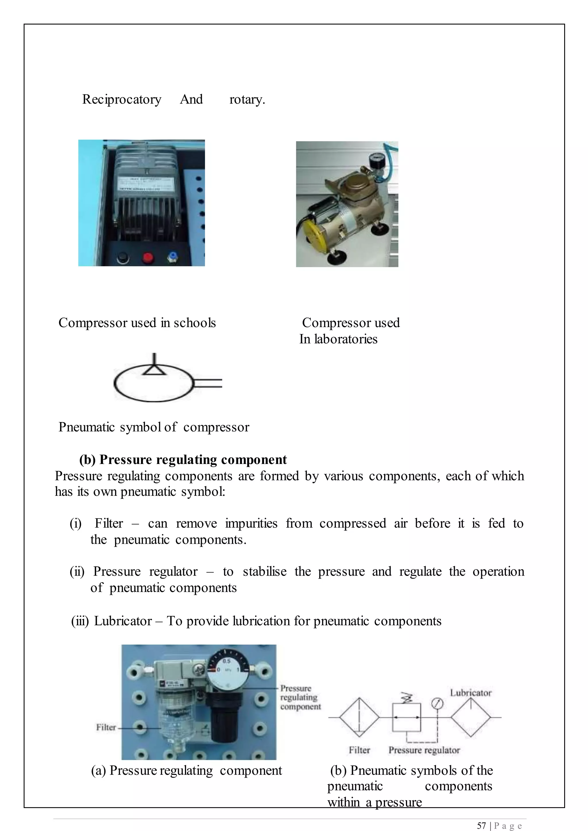
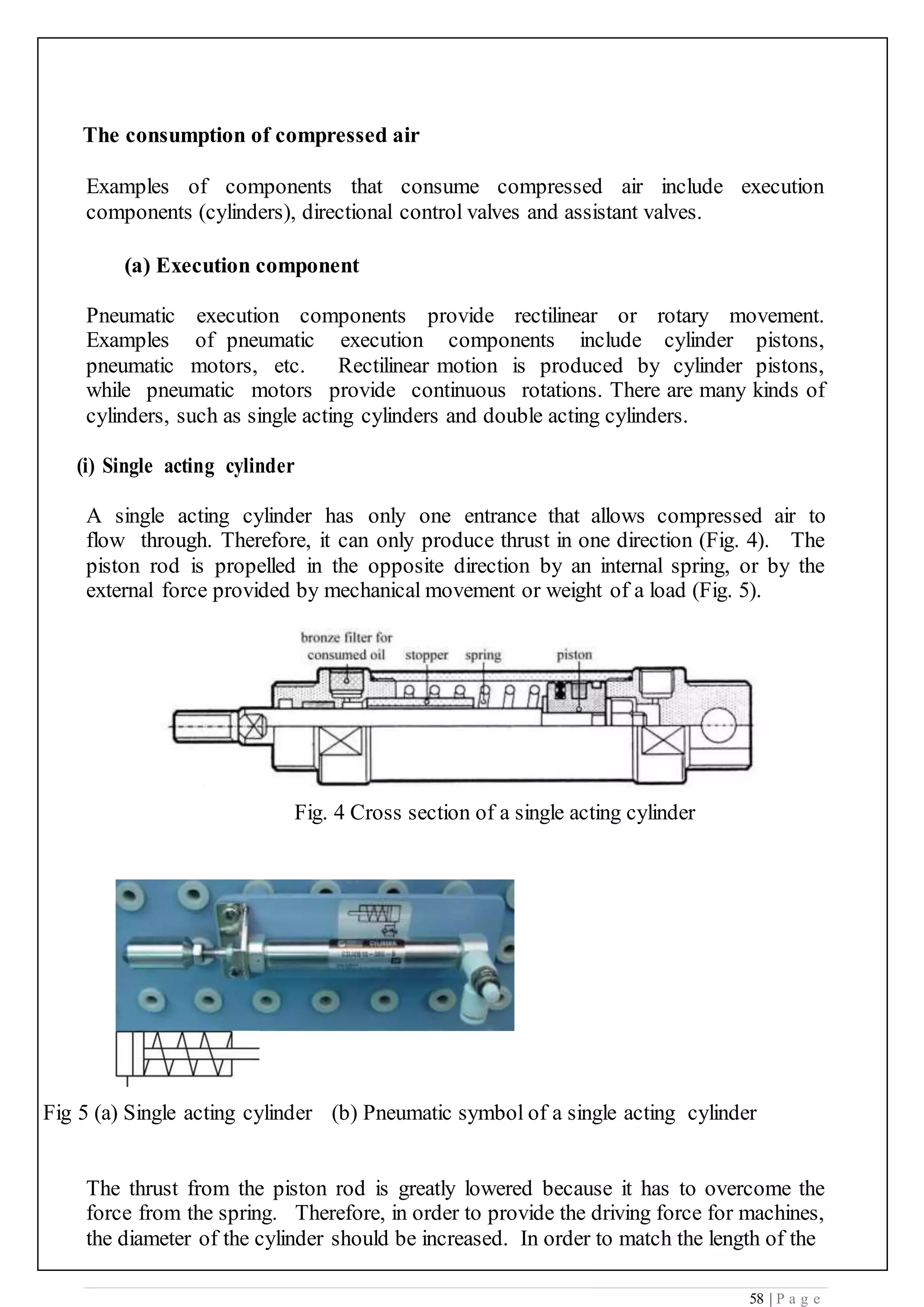
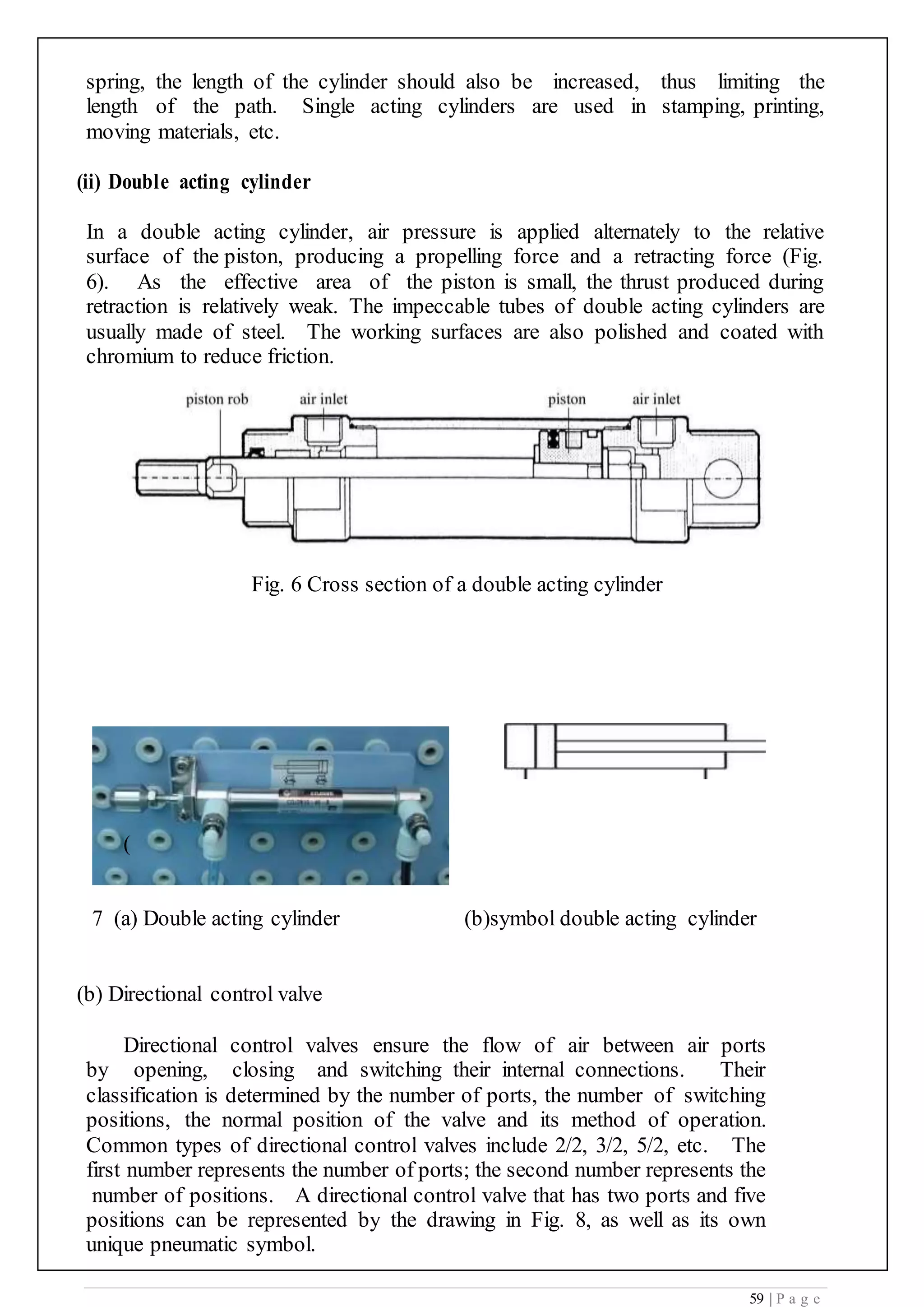
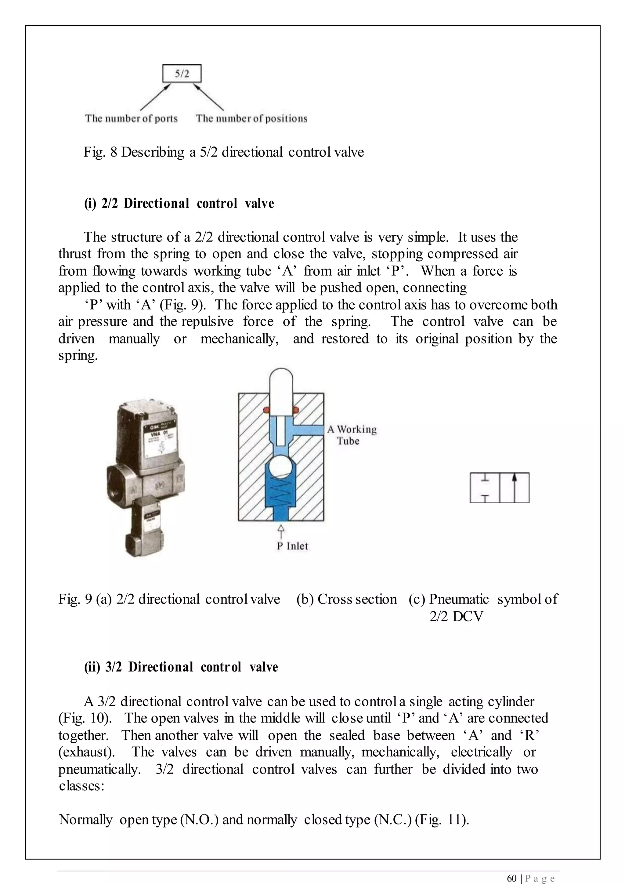
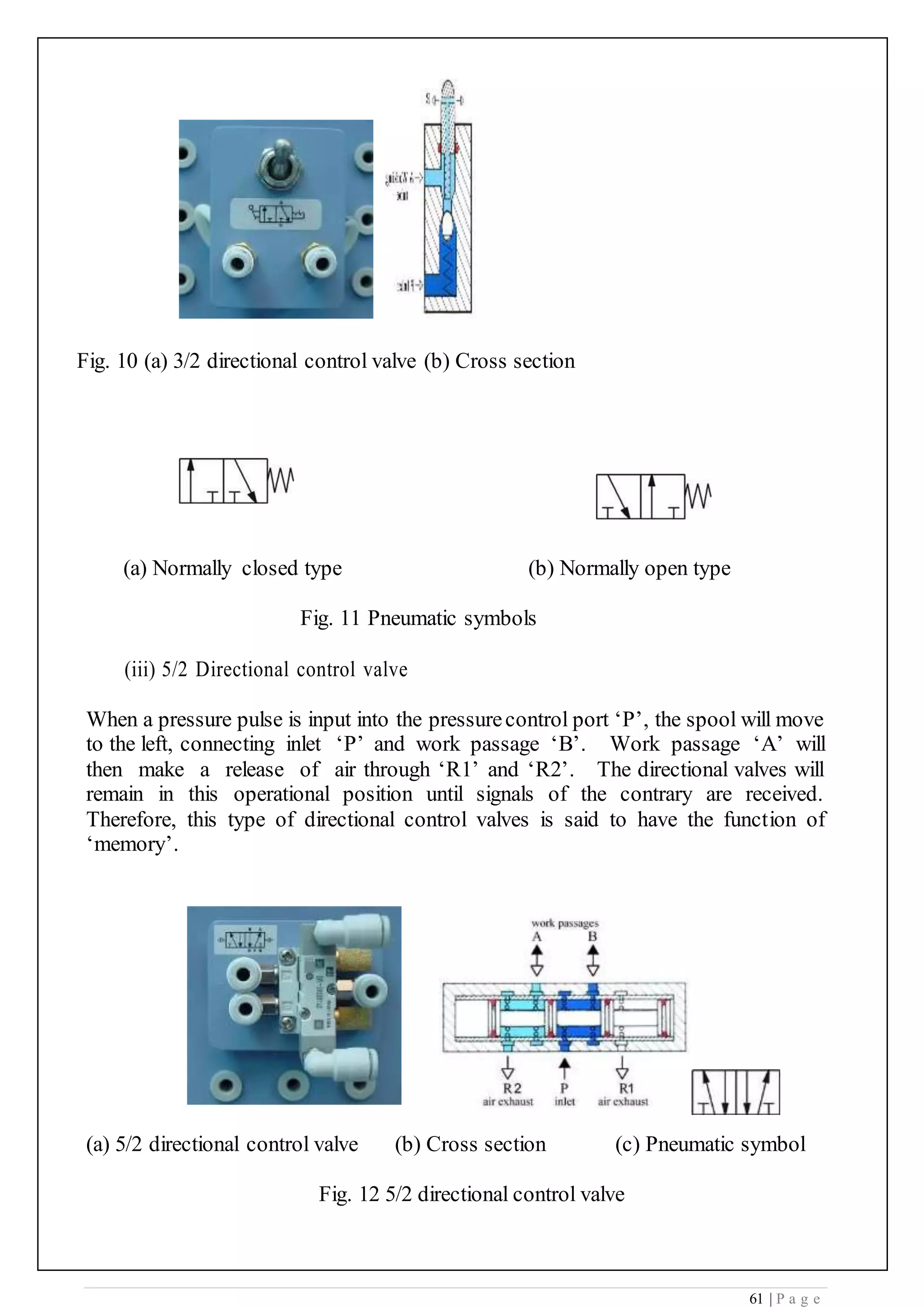
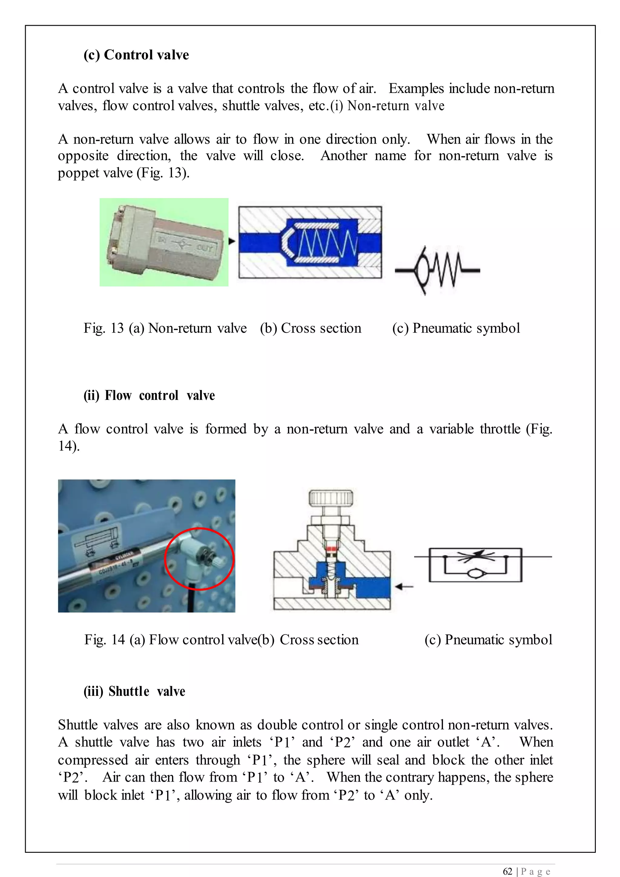
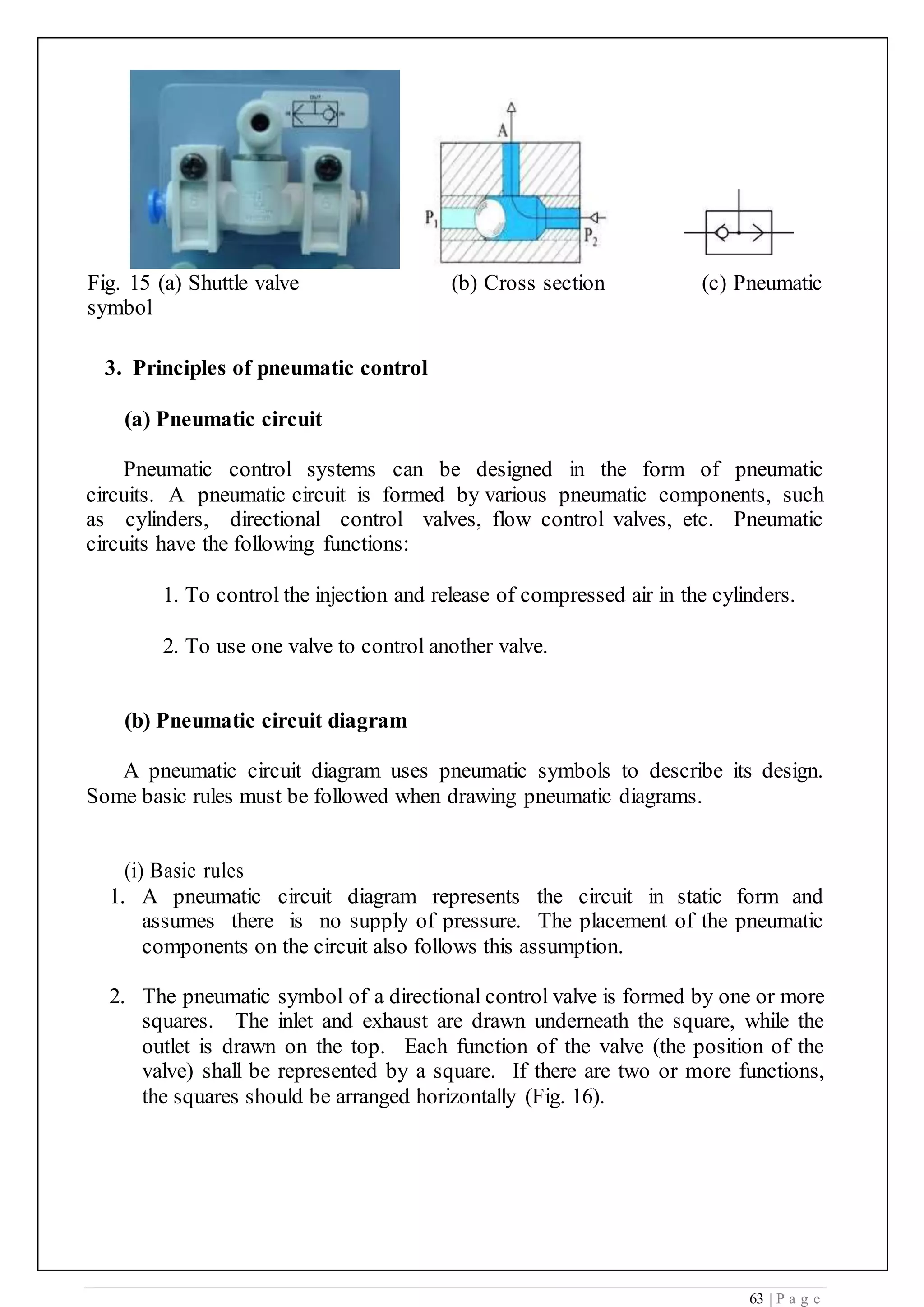
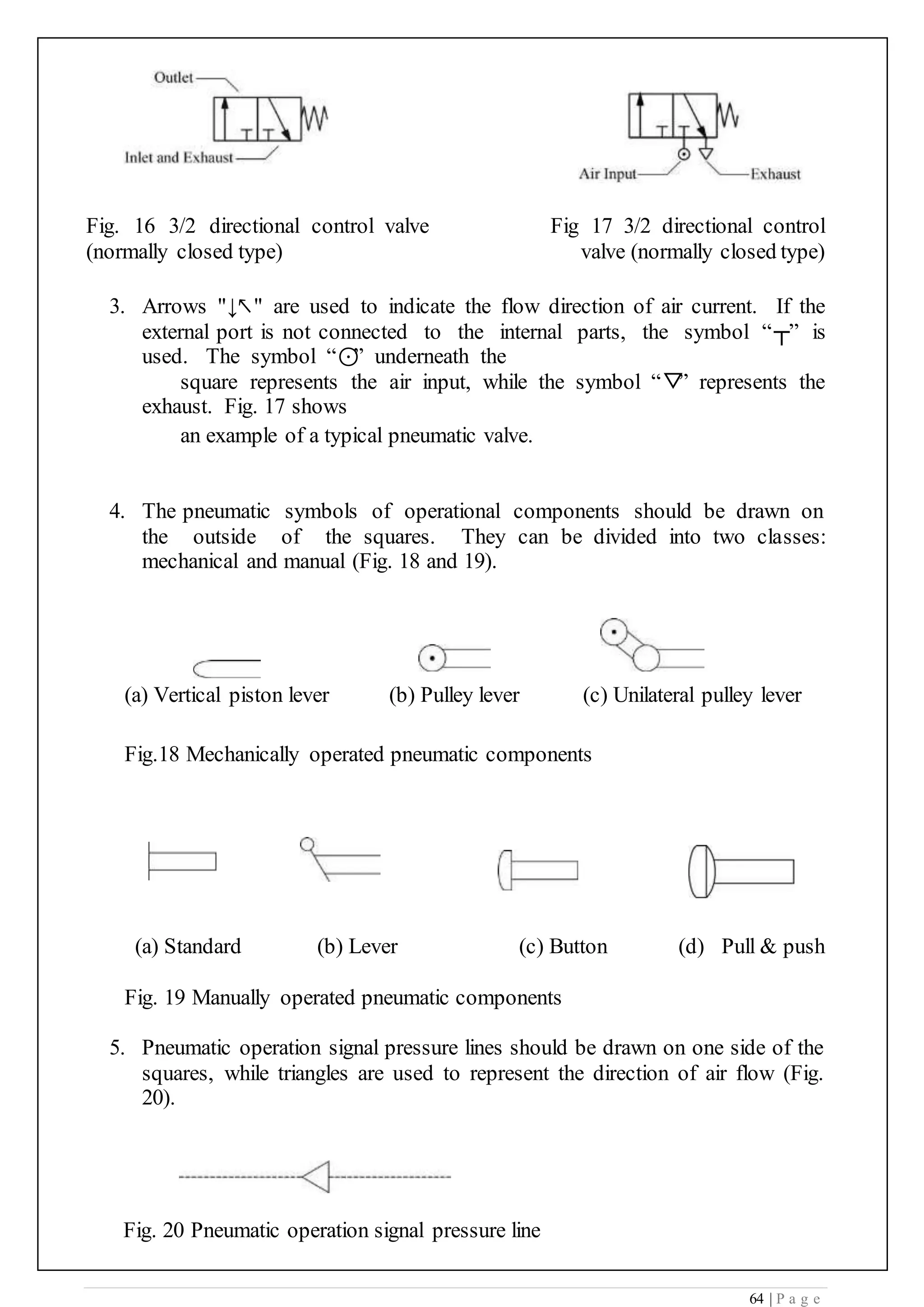
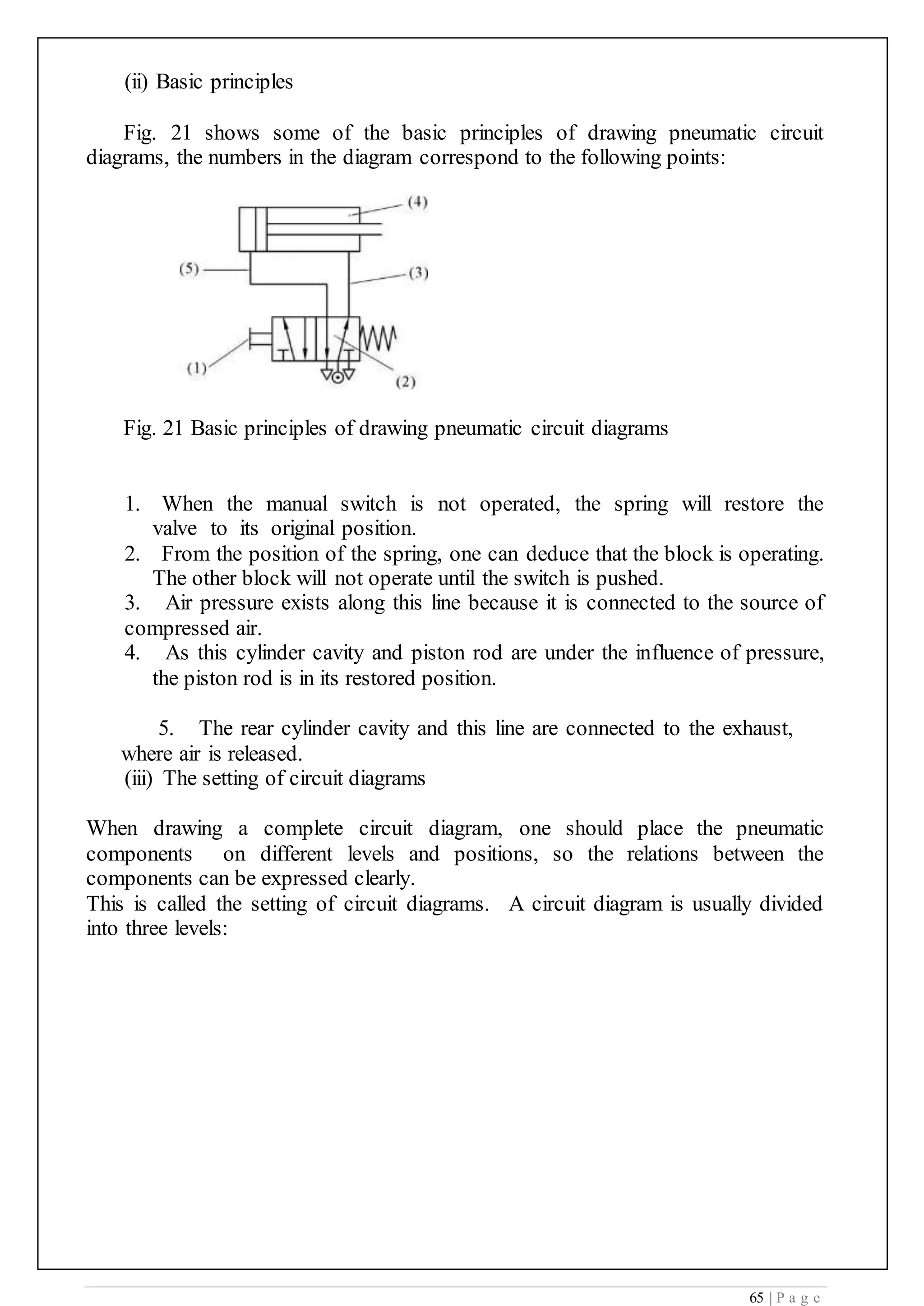
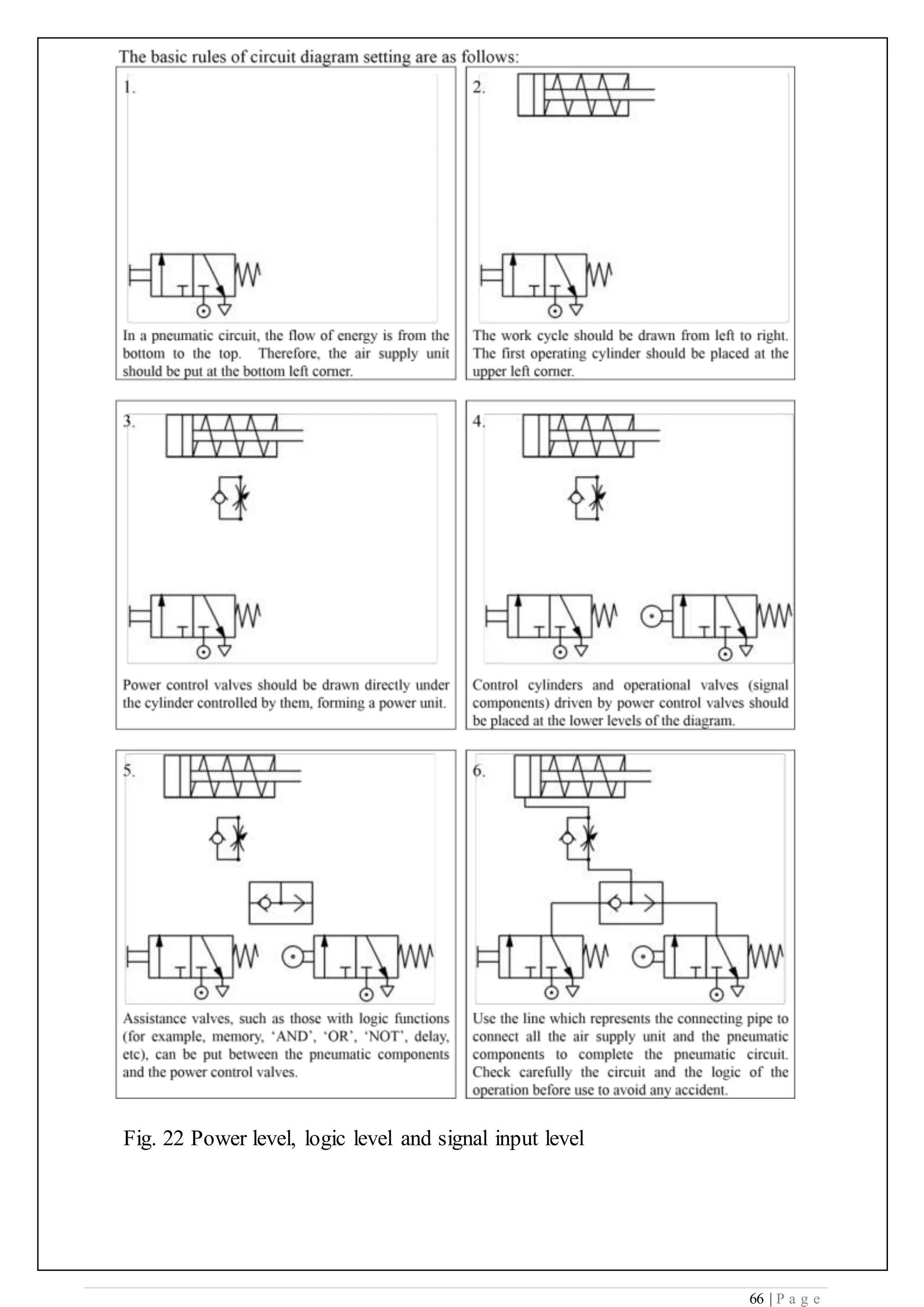
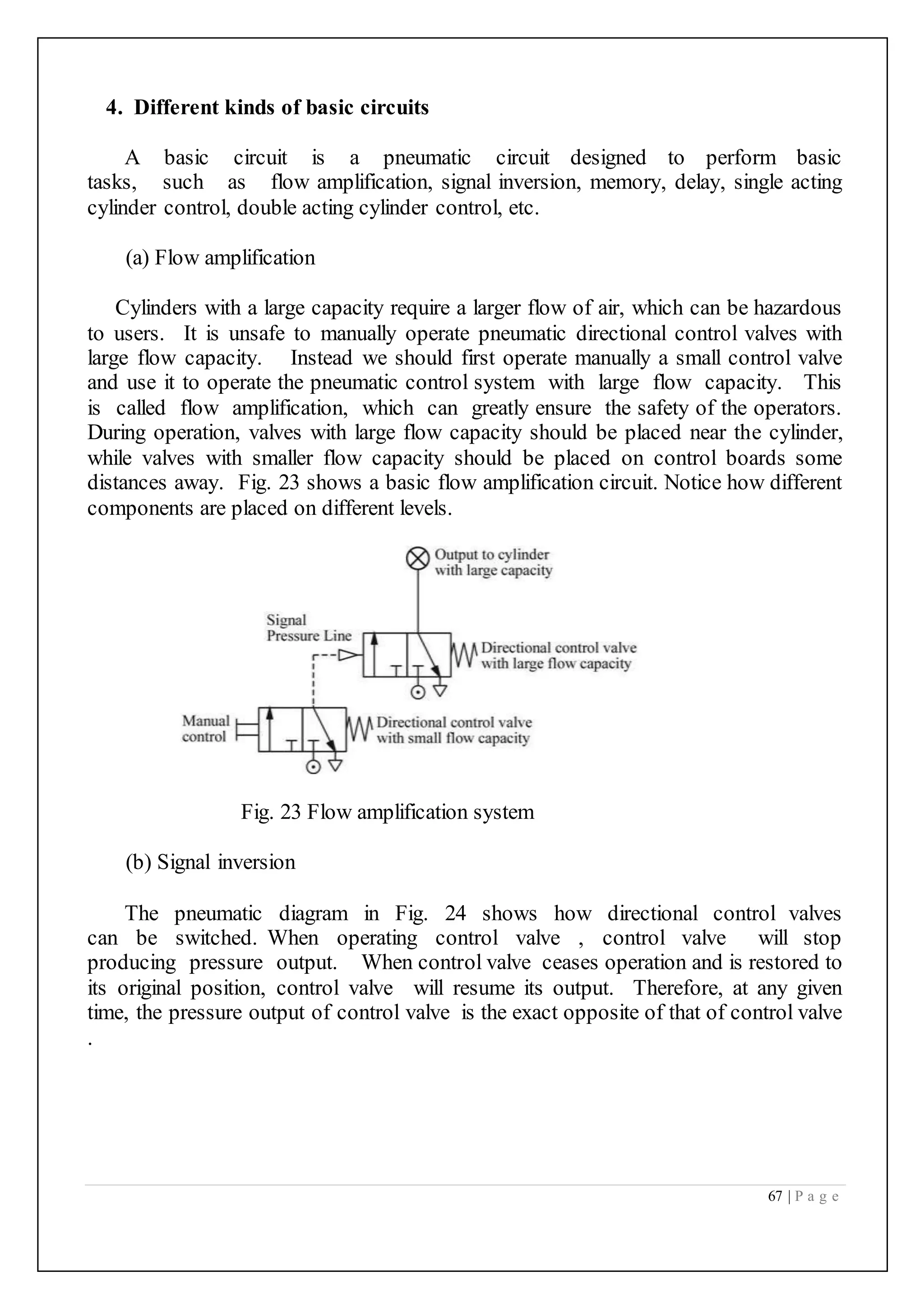
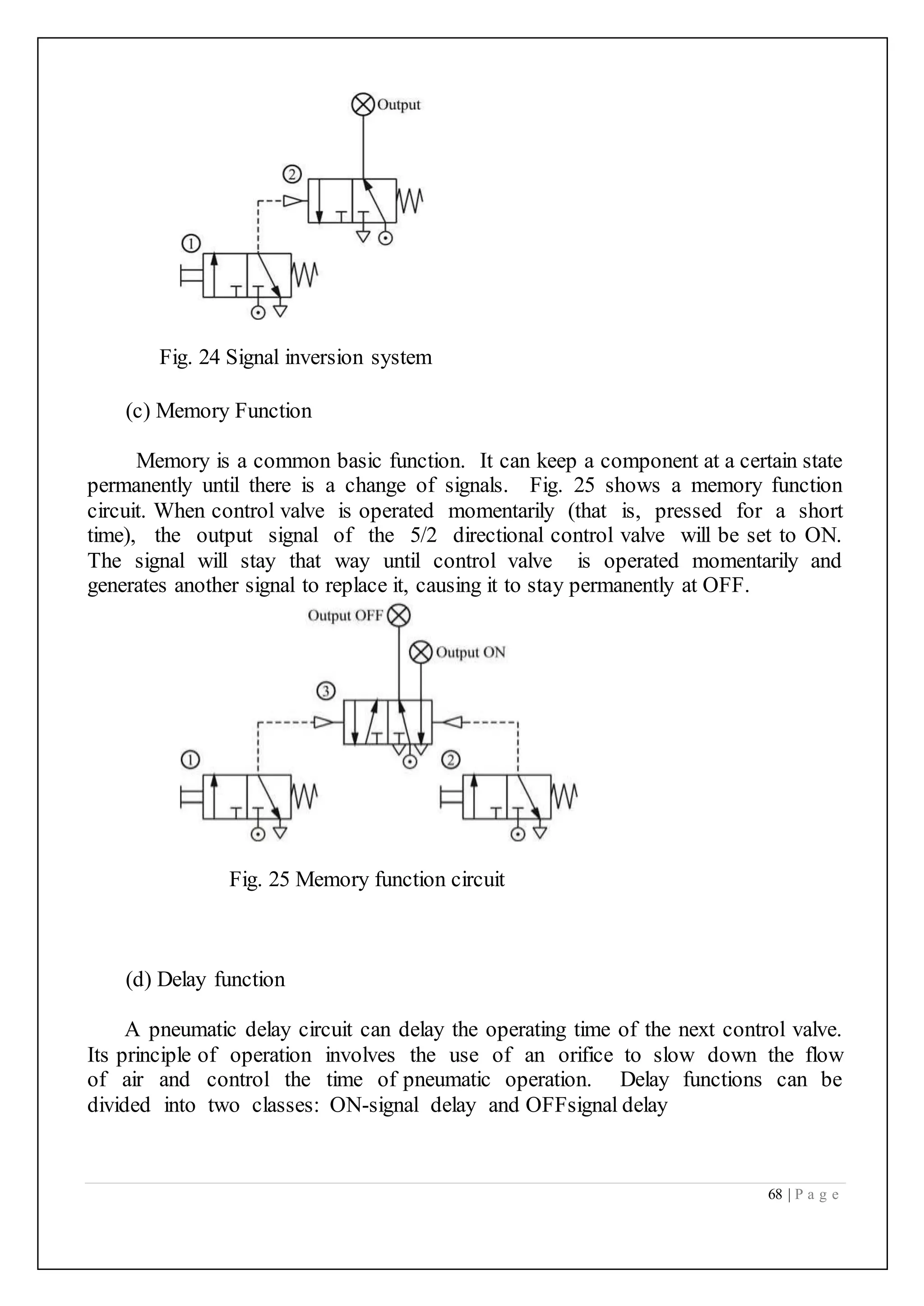
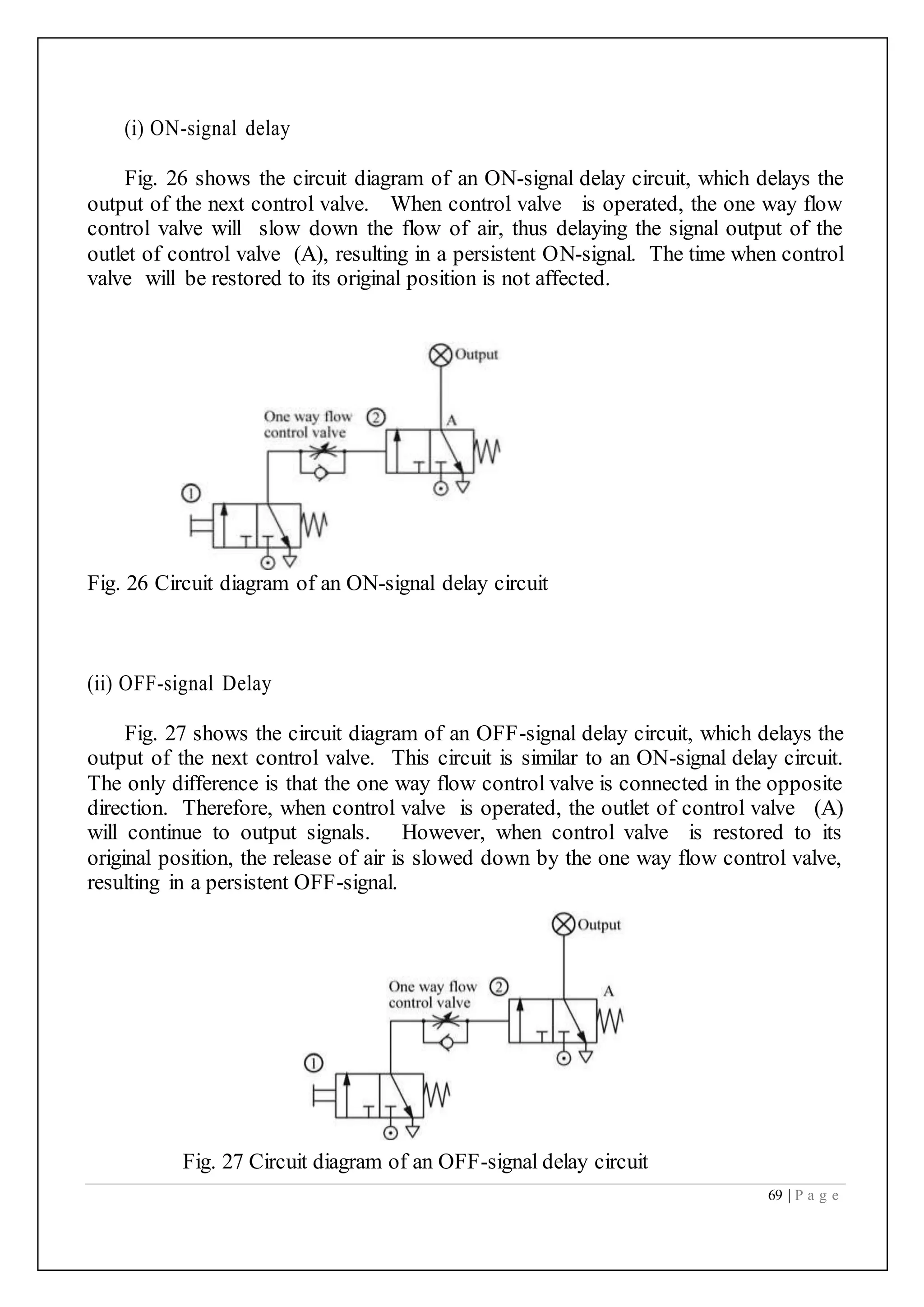
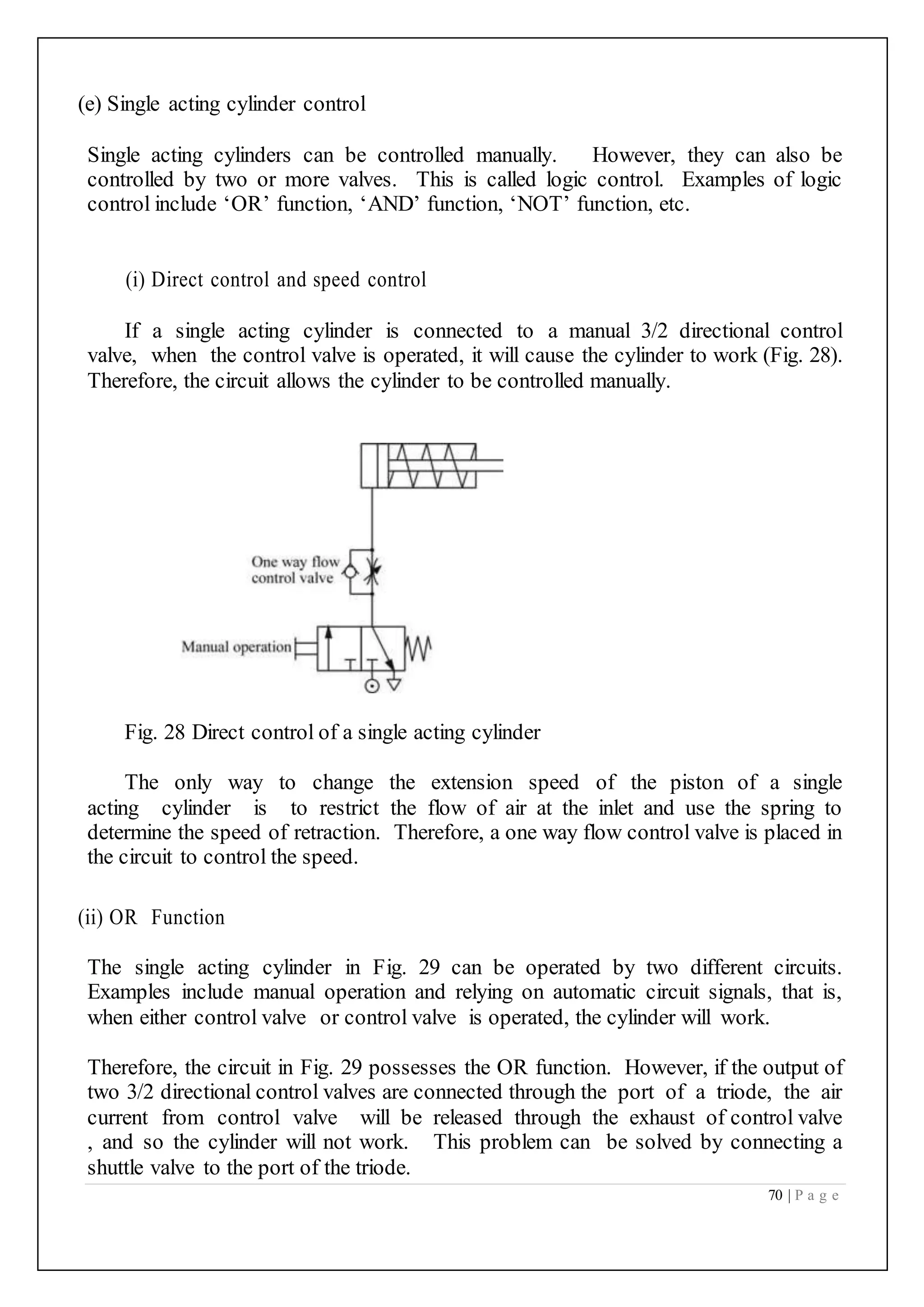
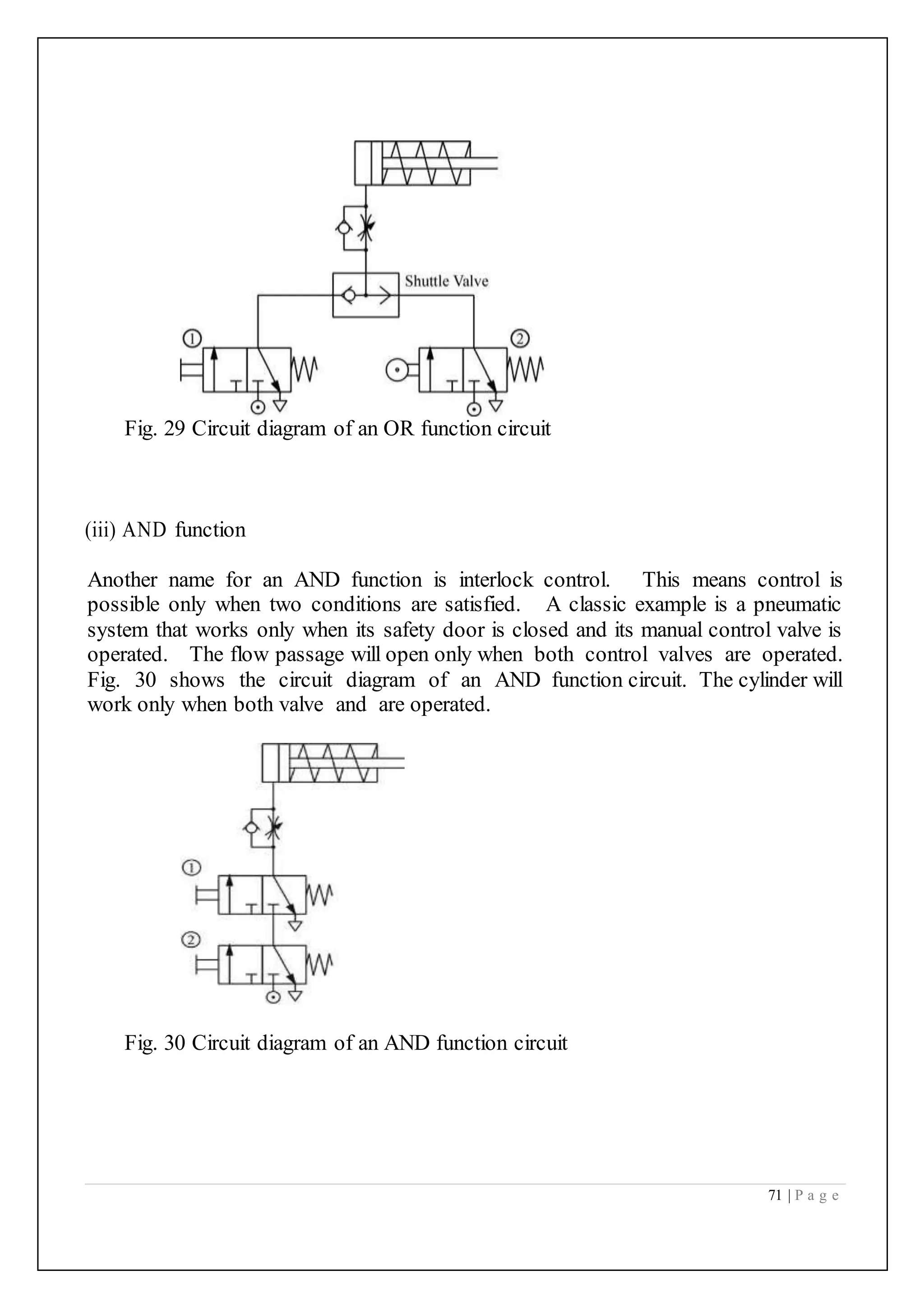
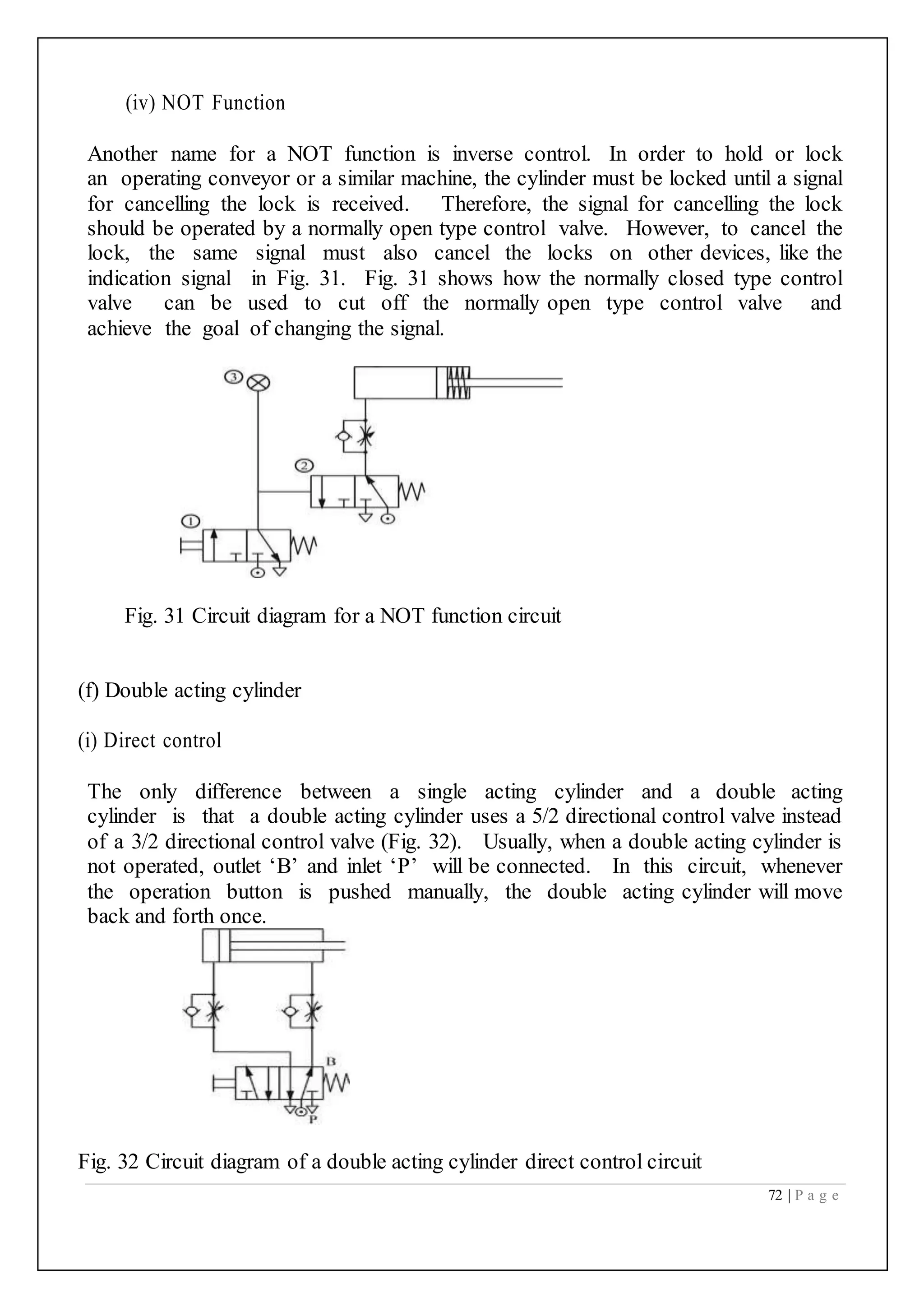
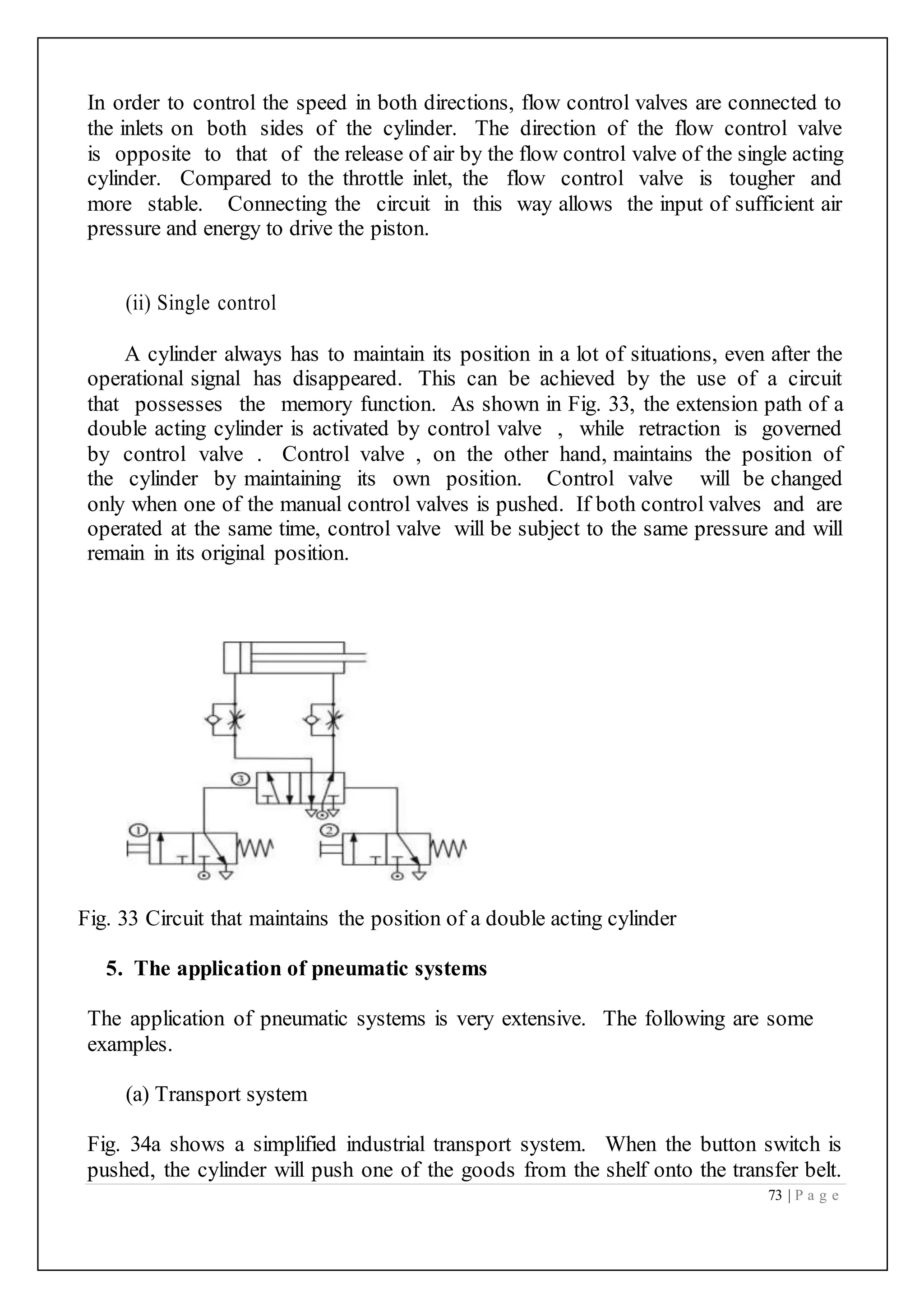
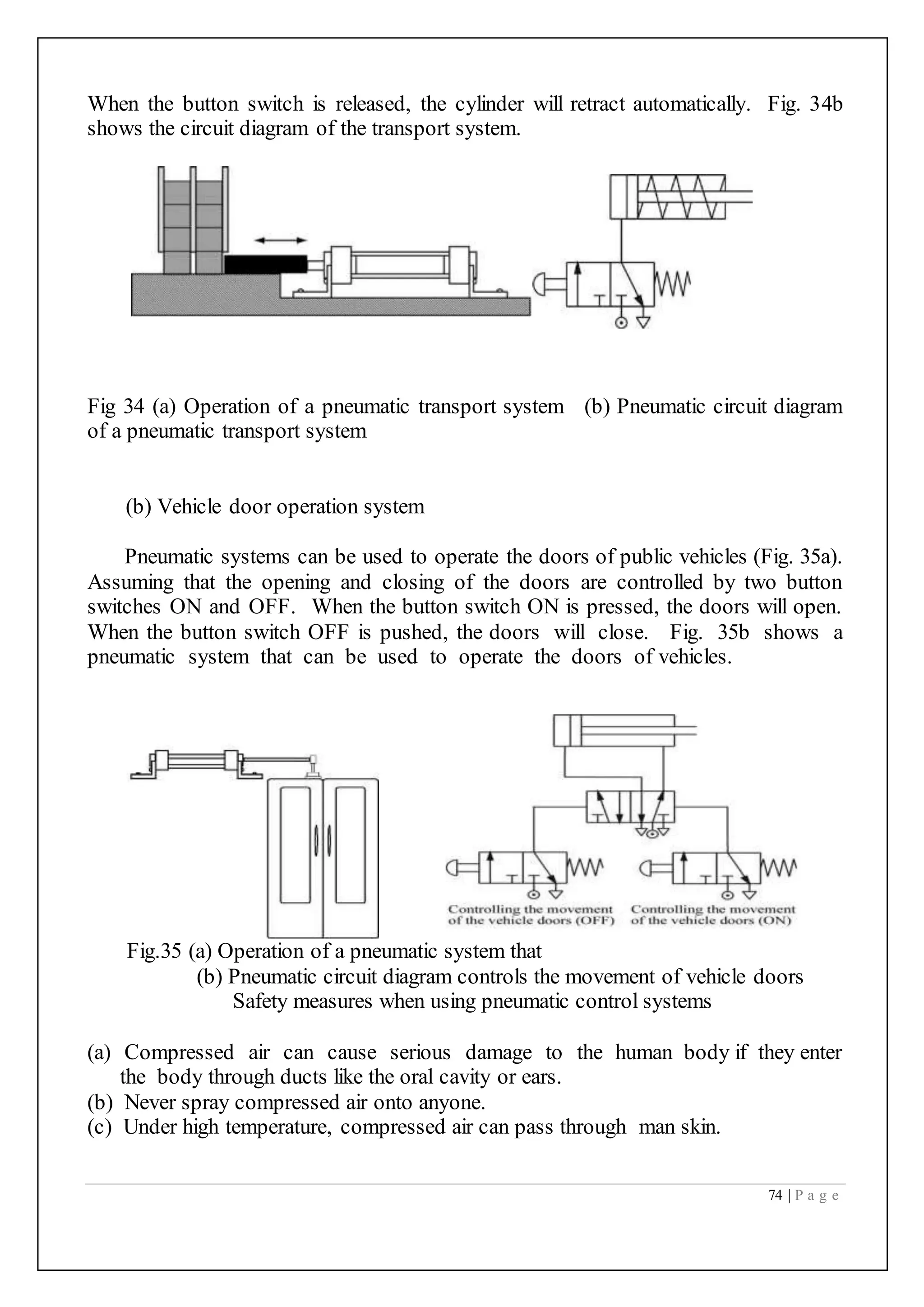
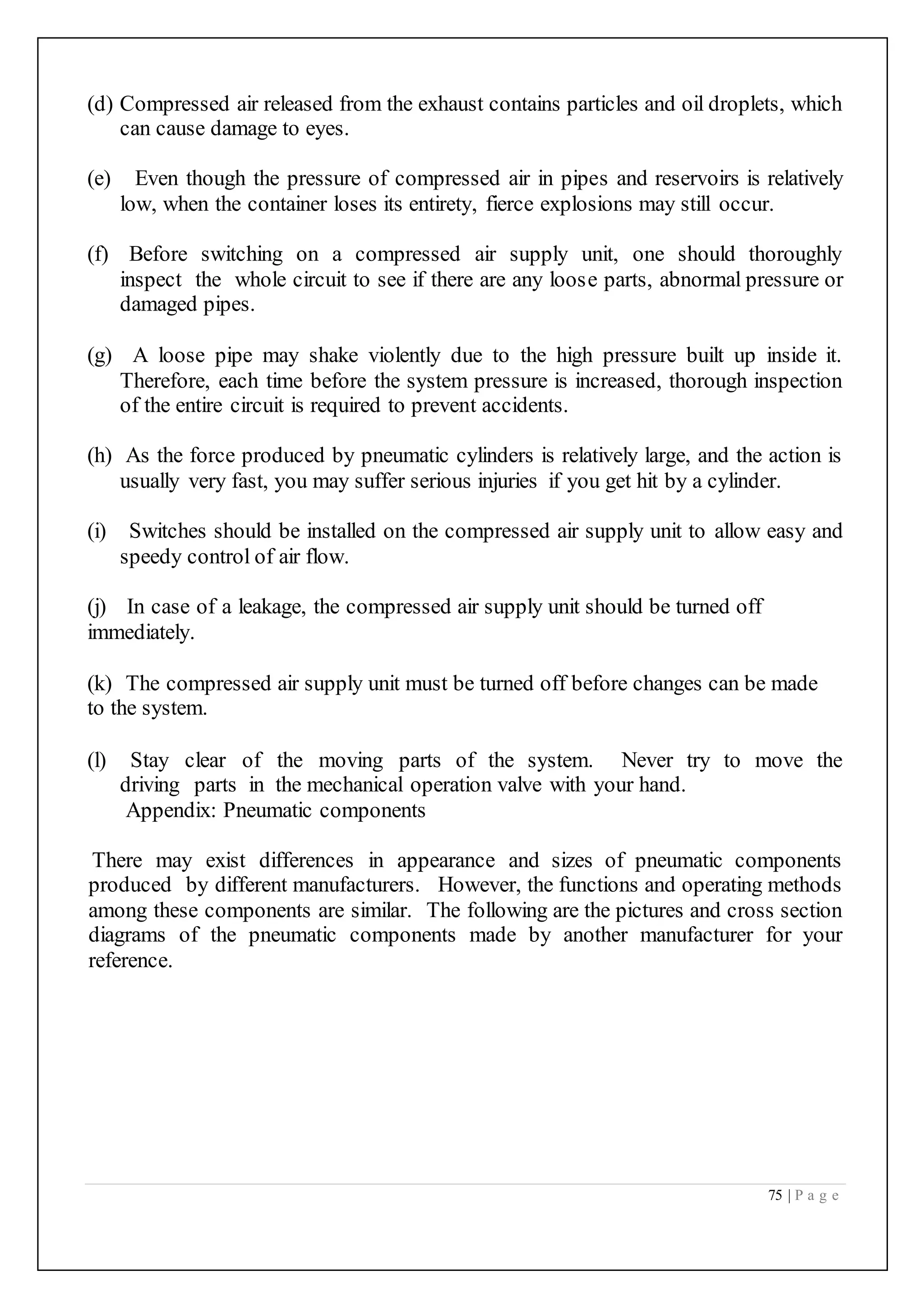
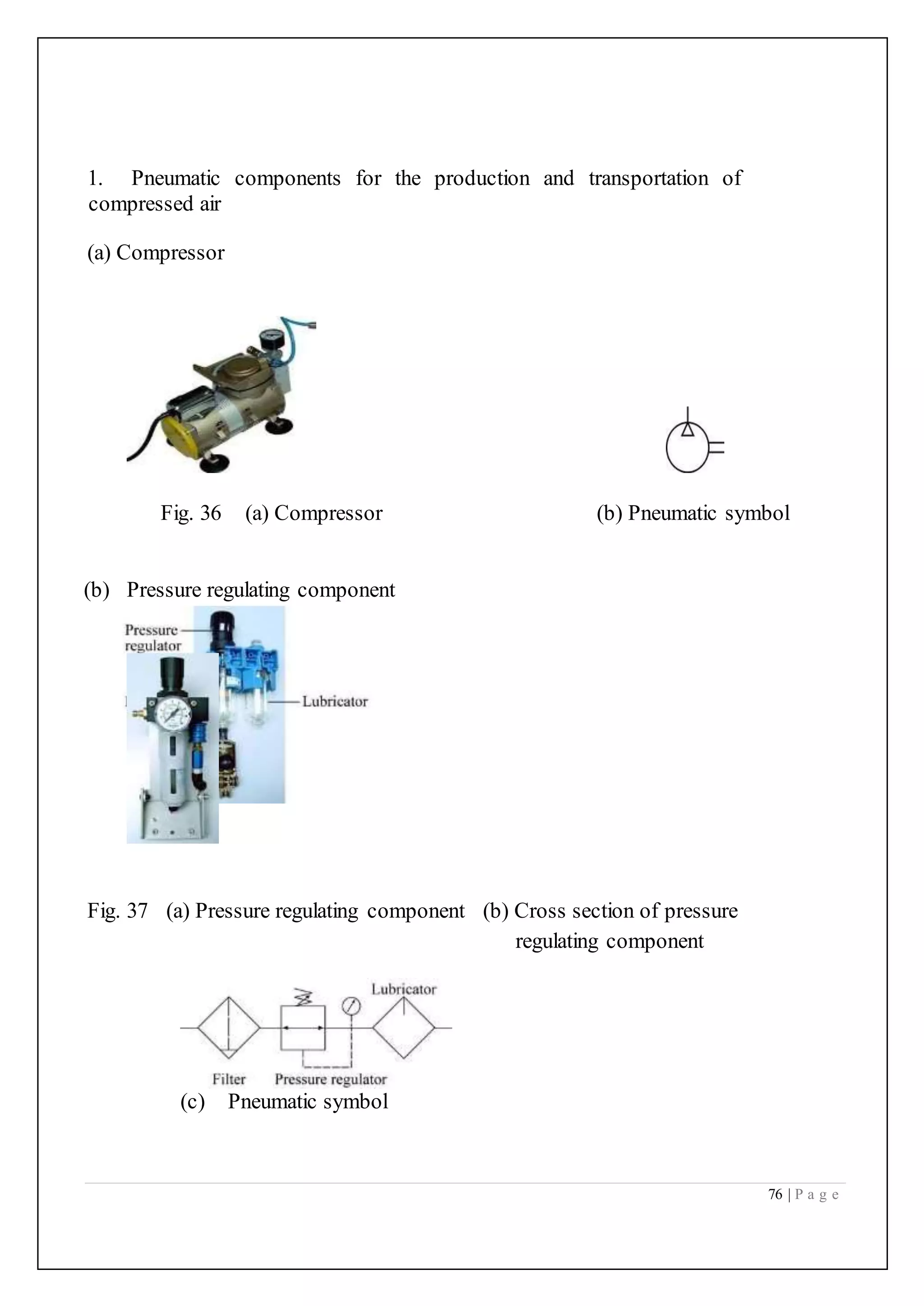
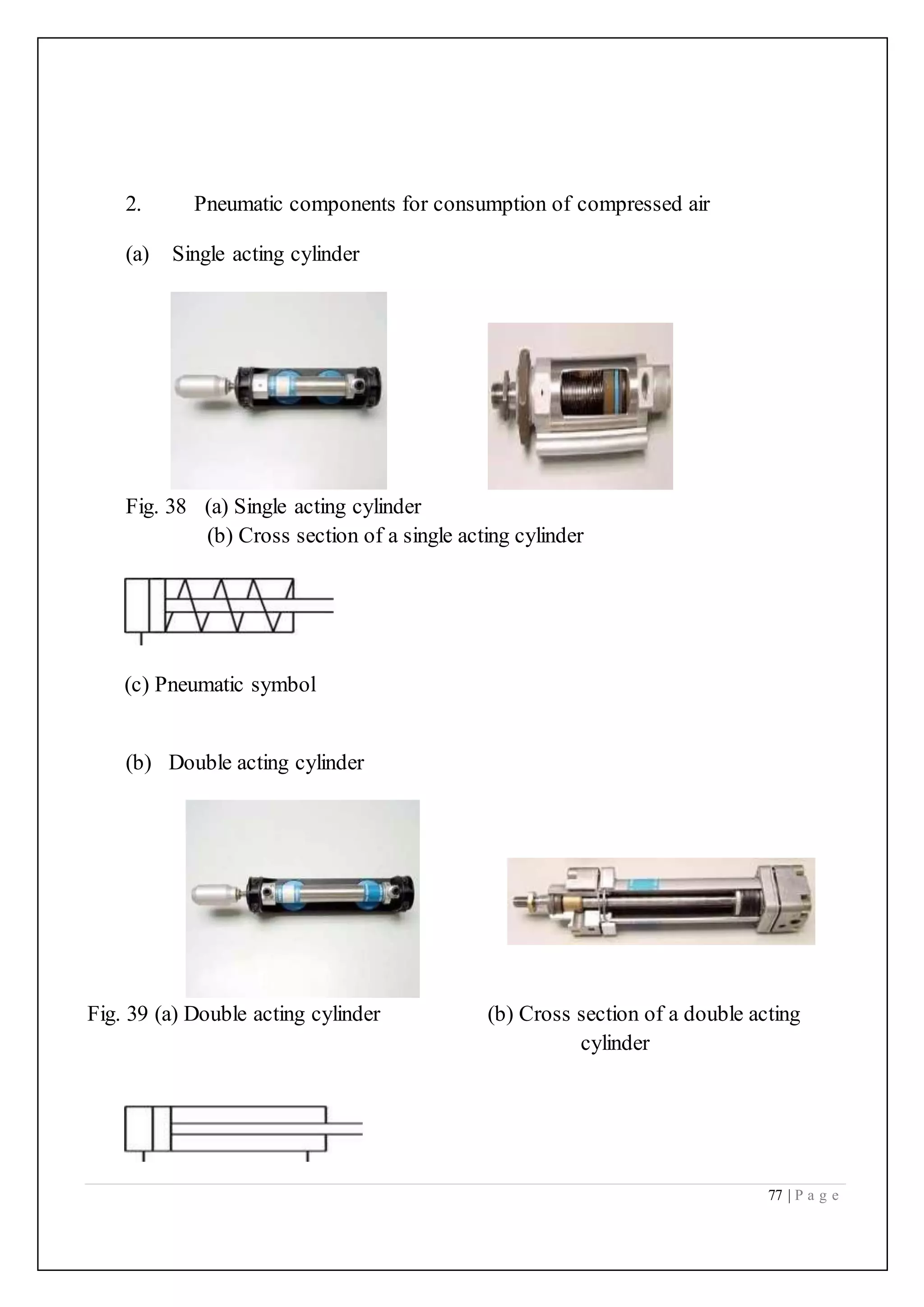
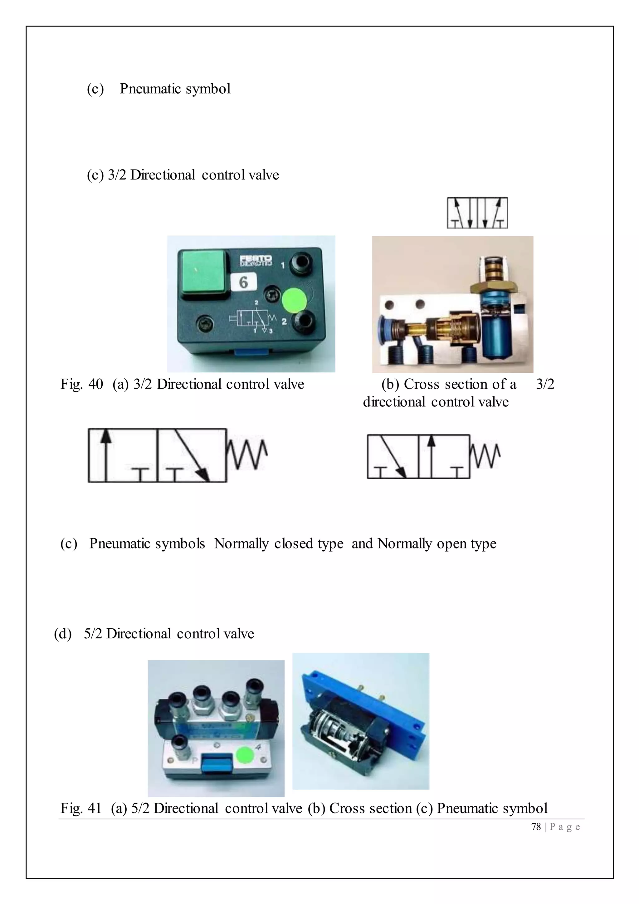
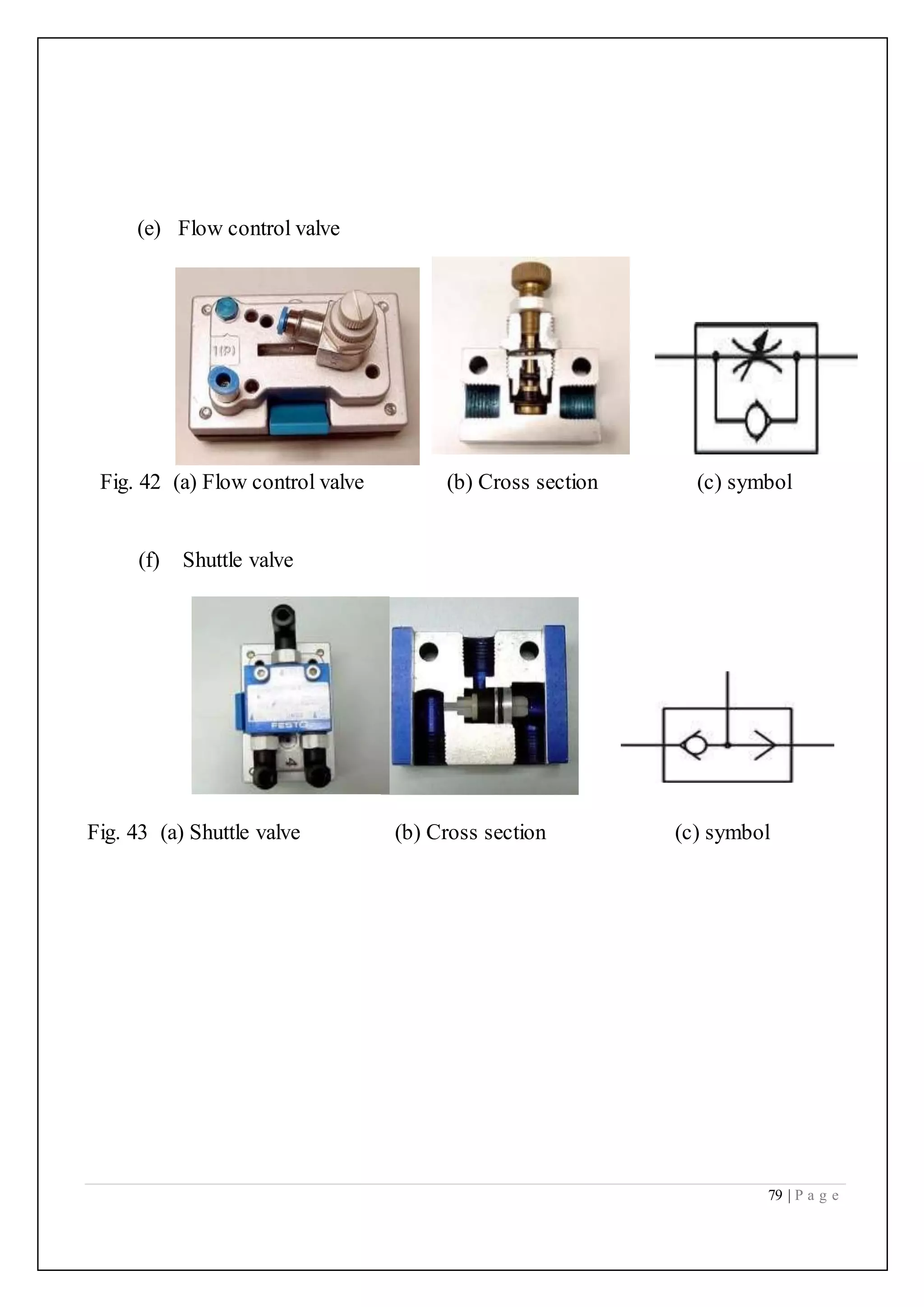
The document discusses pneumatic systems which use compressed air for energy transmission and control, highlighting their applications in industries such as automobile production. It outlines the advantages of pneumatic systems including high effectiveness, durability, adaptability, safety, and cost-effectiveness, as well as their limitations like low accuracy and noise. Additionally, it describes essential components, circuit design, and basic functions of pneumatic control systems, providing details on various types of valves and their operations.