Download as PDF, PPTX


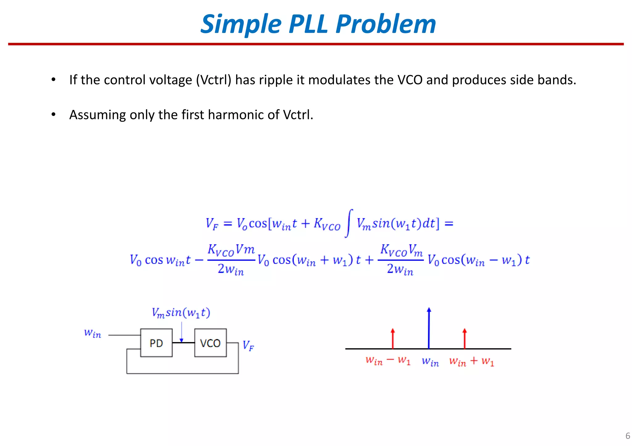
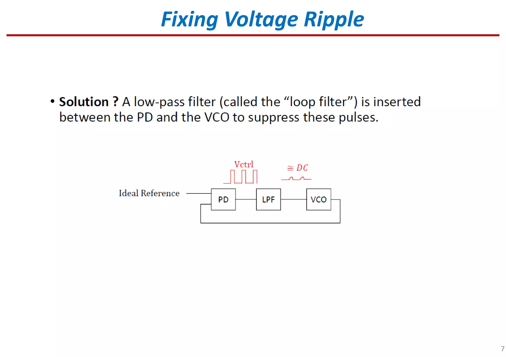


1) A phase-locked loop (PLL) is a control system that generates an output signal whose phase is related to the phase of an input signal, allowing it to synchronize signals or generate a frequency that is a multiple of the input frequency. 2) In a simple PLL, a phase detector (PD) converts the phase difference between the input and a voltage-controlled oscillator (VCO) output to a voltage, which changes the VCO frequency to follow the input. 3) Ripple in the control voltage to the VCO can produce side bands, so a low-pass filter is used to fix this voltage ripple problem and improve stability.
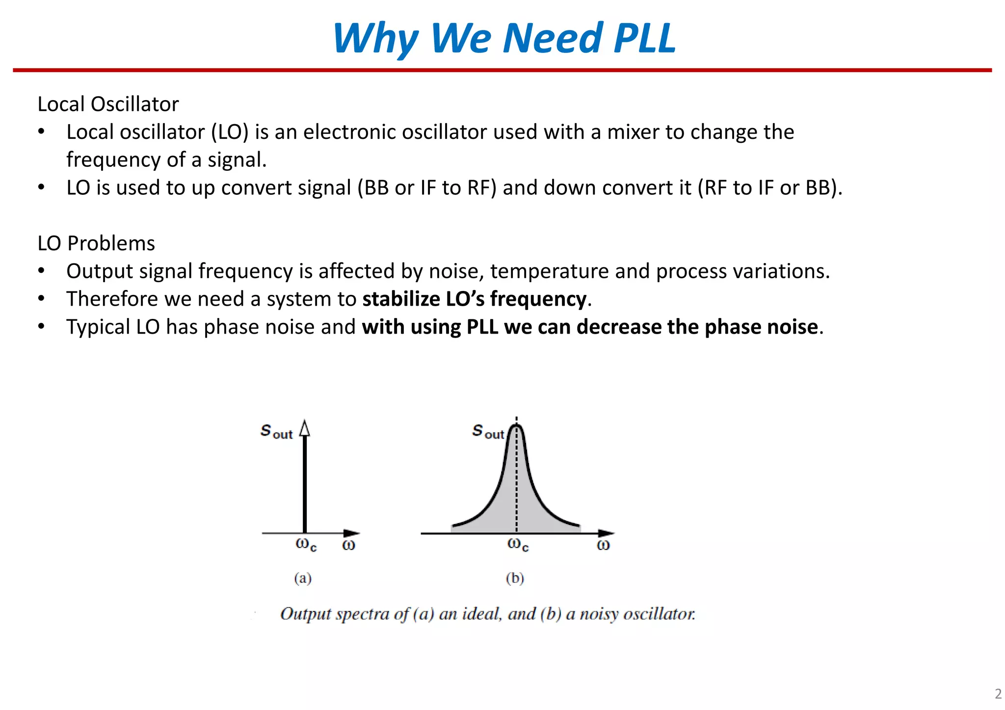
Overview of PLL and its significance in stabilizing local oscillator frequencies.
Defines local oscillator (LO), its role in signal conversion, and PLL's function in reducing phase noise.
Explains PLL as a control system that synchronizes phases and frequencies of signals.
Introduction to the fundamental composition of a PLL, including VCO and phase detector.
Describes the feedback loop in PLL operation and how phase difference is converted to voltage.
Identifies issues due to control voltage ripple affecting VCO performance.
Indicates methods or strategies to fix control voltage ripple found in PLL systems.
Comparison of VCO test results with and without low pass filtering.
Introduction and brief overview of the phase detector functionality in PLL.
Detailed explanation of phase detector operations in PLL systems.
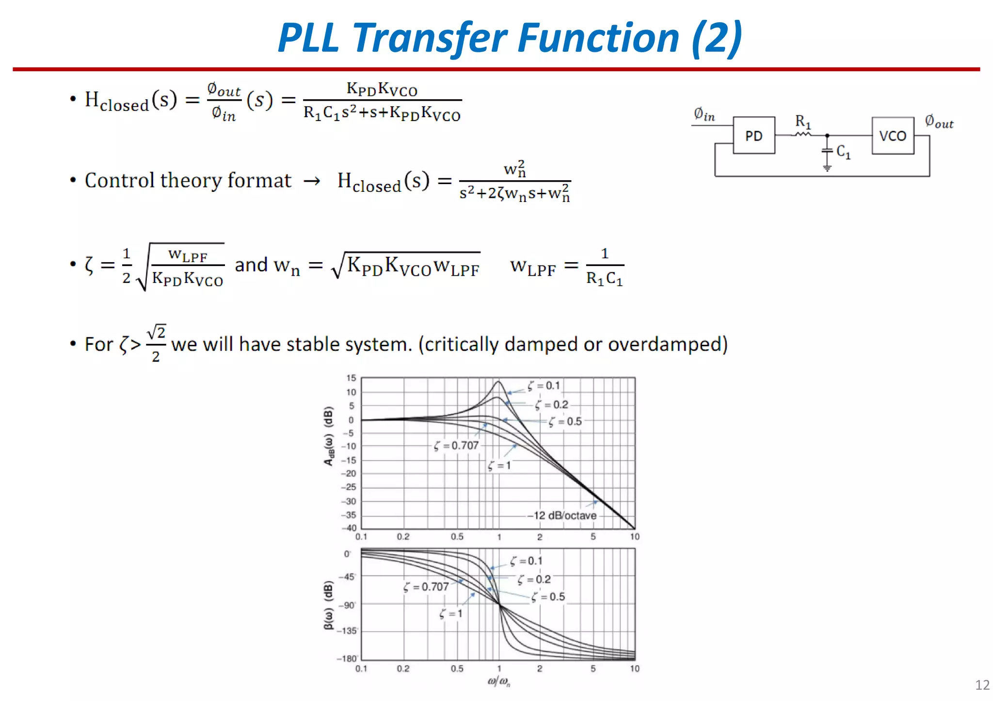
Introduction to PLL transfer functions and their significance in signal processing.
Further analysis of PLL transfer functions and their implications for performance.
Initial examination of phase margin in PLL and its relevance to system stability.
Illustrates Bode plots for type-I PLL and the impact of varying KVCO on stability.
Summarizes the effects of KVCO and KPD on stability issues in PLL systems.


![RF Circuit Design - [Ch2-2] Smith Chart](https://cdn.slidesharecdn.com/ss_thumbnails/ch2-2-150613064401-lva1-app6891-thumbnail.jpg?width=640&height=640&fit=bounds)


