Download as PDF, PPTX
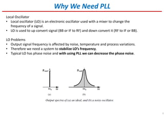
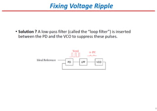
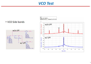
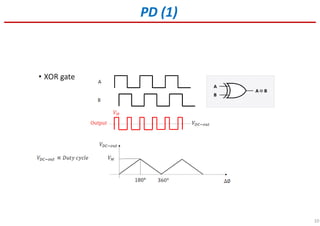
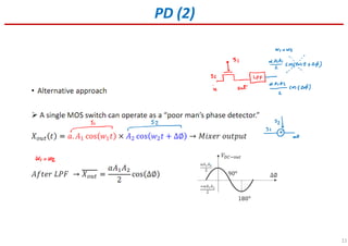
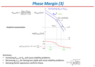
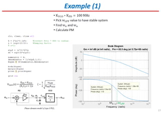
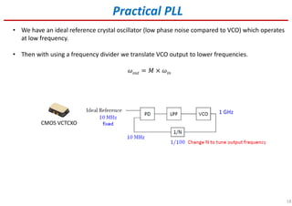
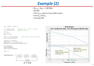
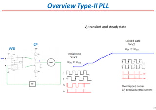
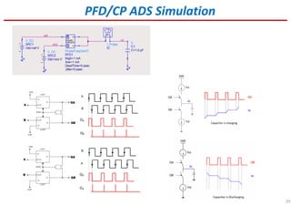
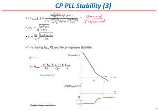
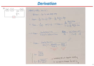
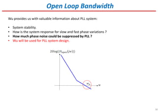
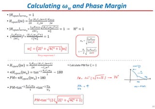
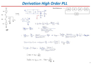
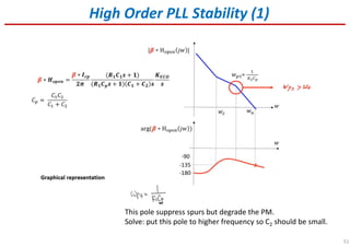
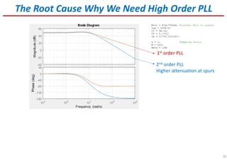


The document provides an overview of phase-locked loops (PLLs), explaining their components such as voltage-controlled oscillators (VCOs) and phase detectors (PDs), as well as their functionality in synchronizing and tracking frequency signals. It discusses issues like stability, phase noise, and the importance of components like charge pumps and phase/frequency detectors in improving performance. Additionally, it outlines design strategies and considerations for achieving optimal bandwidth and minimizing ripple effects in PLLs.


![RF Module Design - [Chapter 6] Power Amplifier](https://cdn.slidesharecdn.com/ss_thumbnails/rfch6-150613070347-lva1-app6891-thumbnail.jpg?width=640&height=640&fit=bounds)


![RF Module Design - [Chapter 8] Phase-Locked Loops](https://cdn.slidesharecdn.com/ss_thumbnails/rfch8-150613070348-lva1-app6892-thumbnail.jpg?width=640&height=640&fit=bounds)


![[Deck] What's New in Spark-Iceberg Integration via DSV2.pptx](https://cdn.slidesharecdn.com/ss_thumbnails/deckwhatsnewinspark-icebergintegrationviadsv2-260210005337-25955b12-thumbnail.jpg?width=640&height=640&fit=bounds)


