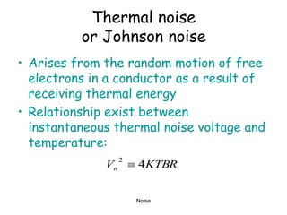
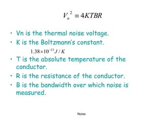
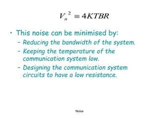
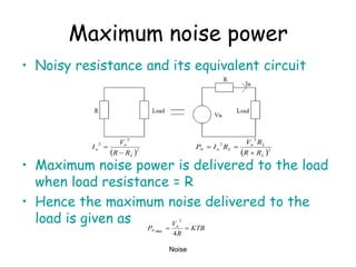
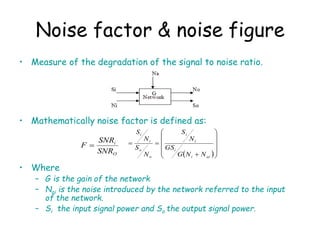
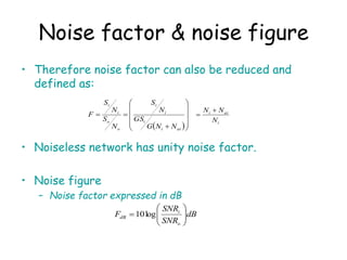
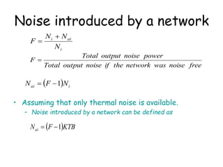
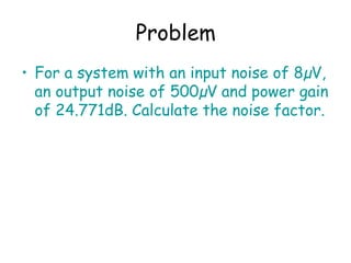
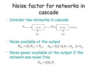
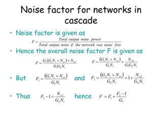
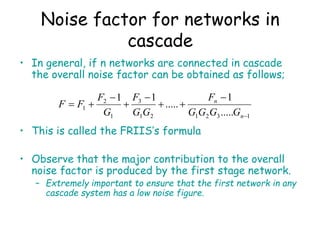
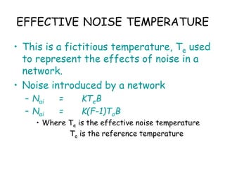
Noise
TELECOMMUNUCATION
NOISE
Presented by
Mr M Nkoloma
To
D3E Students
Noise
NOISE CATEGORIES
– External
• Natural noise
• Man-made noise
– Internal
• Thermal noise
• Shot noise
• Partition noise
• Flicker noise
Noise
External noise
• Noise originating from outside the
communication system.
– Natural noise
• Noise that arise due to natural phenomenon
– eg Lighting, thunderstorm, solar flares and other general
atmospheric disturbances (eg cosmic noise)
– Man-made noise
• Noises that arise due to pick up of undesired signals from
other sources.
– eg faulty electrical contacts, electrical appliances, ignition
radiation, fluorescent lighting.
» Removing the noise source or shielding the
communication system minimise their effects.
Noise
Internal noise
• Noise generated within the components
used in the communication system.
• Difficult to eliminate as they come from
various components.
– Eg:
• Thermal noise or Johnson noise
• Shot noise
• Partition noise
• Flicker noise
Noise
Internal noise cont.
• Internal noise obey certain physics laws.
• An understanding of these laws enables
systems to be designed in such a way as
to minimise their effects.
Noise
Thermal noise
or Johnson noise
• Arises from the random motion of free
electrons in a conductor as a result of
receiving thermal energy
• Relationship exist between
instantaneous thermal noise voltage and
temperature:
KTBR
Vn 4
2

Noise
KTBR
Vn 4
2

• Vn is the thermal noise voltage.
• K is the Boltzmann’s constant.
• T is the absolute temperature of the
conductor.
• R is the resistance of the conductor.
• B is the bandwidth over which noise is
measured.
K
J /
10
38
.
1 23


Noise
• This noise can be minimised by:
– Reducing the bandwidth of the system.
– Keeping the temperature of the
communication system low.
– Designing the communication system
circuits to have a low resistance.
KTBR
Vn 4
2

Noise
Noise equivalent circuit
• Consist of a noise voltage generator in
series with a noiseless resistance, or a
noise current generator in parallel with
noiseless conductance.
Noise
Maximum noise power
• Noisy resistance and its equivalent circuit
• Maximum noise power is delivered to the load
when load resistance = R
• Hence the maximum noise delivered to the
load is given as
 2
2
2
L
n
n
R
R
V
I


 2
2
2
L
L
n
L
n
N
R
R
R
V
R
I
P



KTB
R
V
P n
N 

4
2
max
TELECOMMUNICATION
NOISE
Presented
by
Mr M Nkoloma
to
D3E Students
Signal to Noise ratio
• Telecommunication systems are characterized by the
fact that received signals are always accompanied by
noise.
• Effectiveness is measured in terms of the ratio of
signal power to noise power, SNR.
• SNR measures:
– Performance of the communication system.
– Purity of the signal.
Signal to Noise Ratio
• Signal power is given as:-
• Noise power is given as:-
• Signal to noise ratio (SNR) is given as
– This is usually expressed in decibels (dB)
• Minimum accepted SNR depends on application
– Telephone circuits = 16db
– High quality audio transmission = 60db
– Tv transmission = 47db
R
V
P s
S
4
2

R
V
P N
N
4
2

2
2
2










N
s
N
s
V
V
V
V
SNR









N
s
dB
V
V
SNR log
20
• Measure of the degradation of the signal to noise ratio.
• Mathematically noise factor is defined as:
• Where
– G is the gain of the network
– Nai is the noise introduced by the network referred to the input
of the network.
– Si the input signal power and So the output signal power.
Noise factor & noise figure
O
i
SNR
SNR
F 
 














ai
i
i
i
i
o
o
i
i
N
N
G
GS
N
S
N
S
N
S
• Therefore noise factor can also be reduced and
defined as:
• Noiseless network has unity noise factor.
• Noise figure
– Noise factor expressed in dB
Noise factor & noise figure
dB
SNR
SNR
F
o
i
dB 







 log
10
i
ai
i
N
N
N 

 













ai
i
i
i
i
o
o
i
i
N
N
G
GS
N
S
N
S
N
S
F
Noise introduced by a network
• Assuming that only thermal noise is available.
– Noise introduced by a network can be defined as
i
ai
i
N
N
N
F


free
noise
was
network
the
if
noise
output
Total
power
noise
output
Total
F 
  i
ai N
F
N 1


 KTB
F
Nai 1


Problem
• For a system with an input noise of 8µV,
an output noise of 500µV and power gain
of 24.771dB. Calculate the noise factor.
Noise factor for networks in
cascade
• Consider two networks in cascade
• Noise available at the output
• Noise power available at the output if the
network was noise free
2
1
2
02 a
o N
N
G
N 
   2
1
1
2
02 a
a
i N
N
N
G
G
N 


i
N
G
G
N 2
1
02 
Noise factor for networks in
cascade
• Noise factor is given as
• Hence the overall noise factor F is given as
• But and
• Thus hence
free
noise
was
network
the
if
noise
output
Total
power
noise
output
Total
F 
 
i
a
a
i
N
G
G
N
N
N
G
G
F
2
1
2
1
1
2 


 
i
a
i
a
i
N
G
G
N
N
G
N
N
G
F
2
1
2
1
1
1



 
i
a
i
N
G
N
N
G
F
1
1
1
1


 
i
a
i
a
i
N
G
N
N
G
N
N
G
F
2
2
2
1
2
2 1



i
a
N
G
N
F
2
2
2 1

1
2
1
1
G
F
F
F



Noise factor for networks in
cascade
• In general, if n networks are connected in cascade
the overall noise factor can be obtained as follows;
• This is called the FRIIS’s formula
• Observe that the major contribution to the overall
noise factor is produced by the first stage network.
– Extremely important to ensure that the first network in any
cascade system has a low noise figure.
1
3
2
1
2
1
3
1
2
1
.....
1
.....
1
1









n
n
G
G
G
G
F
G
G
F
G
F
F
F
Problems
• A preamplifier with power gain to be found
and a noise figure of 2.5 dB is cascade with a
mixer with a gain of 2 dB and a noise figure
of 8 dB. Find the preamplifier gain such that
the overall noise figure of the cascade is at
most 4 dB.
– Answer: 8.6 dB
• Given that three amplifiers are connected in
cascade and have the following data: F1 = 7,
F2 = 5, F3 = 4, A1 = 100, A2 = 30 and A3 = 20.
Calculate the overall noise figure in dB.
• F= 4dB
F=F1 + (f2-1)/G1
• Change to non-dB’s
F1=1.778 (ant-log)
F= 2.511
F2= 6.3096
2.511= 1.778 + ( 6.3096-1)/G1
G1= 7.244
G1= 8.5998 (10 log 7.244)
Noise
EFFECTIVE NOISE TEMPERATURE
• This is a fictitious temperature, Te used
to represent the effects of noise in a
network.
• Noise introduced by a network
– Nai = KTeB
– Nai = K(F-1)ToB
• Where Te is the effective noise temperature
To is the reference temperature
EFFECTIVE NOISE TEMPERATURE - Passive
network
• Passive network
– Realized when network gain G<1
– Characterized by insertion loss, L.
• L is the reciprocal of power gain, 1/G
– L = F when a network is matched both at the input and output
• Therefore Te = (F-1)To
• OR Te = (L-1)To for a passive matched network
– L is attenuation loss factor or insertion loss
• F = 1 + Te/To
power
Output
power
Input
L 
EFFECTIVE NOISE TEMPERATURE
• Overall noise factor, F is given as
• From the relationship: F = 1 + Te/To
• Hence the overall effective noise temperature is
given as
• Therefore the overall effective noise
temperature is given as
1
3
2
1
2
1
3
1
2
1
.....
1
.....
1
1









n
n
G
G
G
G
F
G
G
F
G
F
F
F
o
n
en
o
e
o
e
o
e
o
e
T
G
G
G
G
T
T
G
G
T
T
G
T
T
T
T
T
1
3
2
1
2
1
3
1
2
1
.....
.....
1
1








1
3
2
1
2
1
3
1
2
1
.....
.....






n
en
e
e
e
e
G
G
G
G
T
G
G
T
G
T
T
T
Problem
• Consider a receiver system consisting of an antenna with lead-in
cable having a loss factor of L = 1.5dB = F, an RF preamplifier
with a noise figure of 7dB and a gain of 20dB, followed by a
mixer with a noise figure of 10dB and a conversion gain of 8dB,
and finally an integrated-circuit IF amplifier with a noise figure
6dB and a gain of 60dB.
– Find the overall noise figure and noise temperature of the
system. 8.57dB, 1796K
– Find the overall noise figure and noise temperature of the
system with the preamplifier and cable interchanged.
7.12dB, 1203K
• L1= 1.5dB=F1
• F2= 7dB, G2= 20dB
• F3= 10dB, G3= 8dB
• F4= 6dB, G4= 60dB
(Hint= change the dBz into Non-dBz;
using ant-logs)
Noise

NOISE.ppt

  • 1.
  • 2.
    Noise NOISE CATEGORIES – External •Natural noise • Man-made noise – Internal • Thermal noise • Shot noise • Partition noise • Flicker noise
  • 3.
    Noise External noise • Noiseoriginating from outside the communication system. – Natural noise • Noise that arise due to natural phenomenon – eg Lighting, thunderstorm, solar flares and other general atmospheric disturbances (eg cosmic noise) – Man-made noise • Noises that arise due to pick up of undesired signals from other sources. – eg faulty electrical contacts, electrical appliances, ignition radiation, fluorescent lighting. » Removing the noise source or shielding the communication system minimise their effects.
  • 4.
    Noise Internal noise • Noisegenerated within the components used in the communication system. • Difficult to eliminate as they come from various components. – Eg: • Thermal noise or Johnson noise • Shot noise • Partition noise • Flicker noise
  • 5.
    Noise Internal noise cont. •Internal noise obey certain physics laws. • An understanding of these laws enables systems to be designed in such a way as to minimise their effects.
  • 6.
    Noise Thermal noise or Johnsonnoise • Arises from the random motion of free electrons in a conductor as a result of receiving thermal energy • Relationship exist between instantaneous thermal noise voltage and temperature: KTBR Vn 4 2 
  • 7.
    Noise KTBR Vn 4 2  • Vnis the thermal noise voltage. • K is the Boltzmann’s constant. • T is the absolute temperature of the conductor. • R is the resistance of the conductor. • B is the bandwidth over which noise is measured. K J / 10 38 . 1 23  
  • 8.
    Noise • This noisecan be minimised by: – Reducing the bandwidth of the system. – Keeping the temperature of the communication system low. – Designing the communication system circuits to have a low resistance. KTBR Vn 4 2 
  • 9.
    Noise Noise equivalent circuit •Consist of a noise voltage generator in series with a noiseless resistance, or a noise current generator in parallel with noiseless conductance.
  • 10.
    Noise Maximum noise power •Noisy resistance and its equivalent circuit • Maximum noise power is delivered to the load when load resistance = R • Hence the maximum noise delivered to the load is given as  2 2 2 L n n R R V I    2 2 2 L L n L n N R R R V R I P    KTB R V P n N   4 2 max
  • 11.
  • 12.
    Signal to Noiseratio • Telecommunication systems are characterized by the fact that received signals are always accompanied by noise. • Effectiveness is measured in terms of the ratio of signal power to noise power, SNR. • SNR measures: – Performance of the communication system. – Purity of the signal.
  • 13.
    Signal to NoiseRatio • Signal power is given as:- • Noise power is given as:- • Signal to noise ratio (SNR) is given as – This is usually expressed in decibels (dB) • Minimum accepted SNR depends on application – Telephone circuits = 16db – High quality audio transmission = 60db – Tv transmission = 47db R V P s S 4 2  R V P N N 4 2  2 2 2           N s N s V V V V SNR          N s dB V V SNR log 20
  • 14.
    • Measure ofthe degradation of the signal to noise ratio. • Mathematically noise factor is defined as: • Where – G is the gain of the network – Nai is the noise introduced by the network referred to the input of the network. – Si the input signal power and So the output signal power. Noise factor & noise figure O i SNR SNR F                  ai i i i i o o i i N N G GS N S N S N S
  • 15.
    • Therefore noisefactor can also be reduced and defined as: • Noiseless network has unity noise factor. • Noise figure – Noise factor expressed in dB Noise factor & noise figure dB SNR SNR F o i dB          log 10 i ai i N N N                  ai i i i i o o i i N N G GS N S N S N S F
  • 16.
    Noise introduced bya network • Assuming that only thermal noise is available. – Noise introduced by a network can be defined as i ai i N N N F   free noise was network the if noise output Total power noise output Total F    i ai N F N 1    KTB F Nai 1  
  • 17.
    Problem • For asystem with an input noise of 8µV, an output noise of 500µV and power gain of 24.771dB. Calculate the noise factor.
  • 18.
    Noise factor fornetworks in cascade • Consider two networks in cascade • Noise available at the output • Noise power available at the output if the network was noise free 2 1 2 02 a o N N G N     2 1 1 2 02 a a i N N N G G N    i N G G N 2 1 02 
  • 19.
    Noise factor fornetworks in cascade • Noise factor is given as • Hence the overall noise factor F is given as • But and • Thus hence free noise was network the if noise output Total power noise output Total F    i a a i N G G N N N G G F 2 1 2 1 1 2      i a i a i N G G N N G N N G F 2 1 2 1 1 1      i a i N G N N G F 1 1 1 1     i a i a i N G N N G N N G F 2 2 2 1 2 2 1    i a N G N F 2 2 2 1  1 2 1 1 G F F F   
  • 20.
    Noise factor fornetworks in cascade • In general, if n networks are connected in cascade the overall noise factor can be obtained as follows; • This is called the FRIIS’s formula • Observe that the major contribution to the overall noise factor is produced by the first stage network. – Extremely important to ensure that the first network in any cascade system has a low noise figure. 1 3 2 1 2 1 3 1 2 1 ..... 1 ..... 1 1          n n G G G G F G G F G F F F
  • 21.
    Problems • A preamplifierwith power gain to be found and a noise figure of 2.5 dB is cascade with a mixer with a gain of 2 dB and a noise figure of 8 dB. Find the preamplifier gain such that the overall noise figure of the cascade is at most 4 dB. – Answer: 8.6 dB • Given that three amplifiers are connected in cascade and have the following data: F1 = 7, F2 = 5, F3 = 4, A1 = 100, A2 = 30 and A3 = 20. Calculate the overall noise figure in dB.
  • 22.
    • F= 4dB F=F1+ (f2-1)/G1 • Change to non-dB’s F1=1.778 (ant-log) F= 2.511 F2= 6.3096 2.511= 1.778 + ( 6.3096-1)/G1 G1= 7.244 G1= 8.5998 (10 log 7.244) Noise
  • 23.
    EFFECTIVE NOISE TEMPERATURE •This is a fictitious temperature, Te used to represent the effects of noise in a network. • Noise introduced by a network – Nai = KTeB – Nai = K(F-1)ToB • Where Te is the effective noise temperature To is the reference temperature
  • 24.
    EFFECTIVE NOISE TEMPERATURE- Passive network • Passive network – Realized when network gain G<1 – Characterized by insertion loss, L. • L is the reciprocal of power gain, 1/G – L = F when a network is matched both at the input and output • Therefore Te = (F-1)To • OR Te = (L-1)To for a passive matched network – L is attenuation loss factor or insertion loss • F = 1 + Te/To power Output power Input L 
  • 25.
    EFFECTIVE NOISE TEMPERATURE •Overall noise factor, F is given as • From the relationship: F = 1 + Te/To • Hence the overall effective noise temperature is given as • Therefore the overall effective noise temperature is given as 1 3 2 1 2 1 3 1 2 1 ..... 1 ..... 1 1          n n G G G G F G G F G F F F o n en o e o e o e o e T G G G G T T G G T T G T T T T T 1 3 2 1 2 1 3 1 2 1 ..... ..... 1 1         1 3 2 1 2 1 3 1 2 1 ..... .....       n en e e e e G G G G T G G T G T T T
  • 26.
    Problem • Consider areceiver system consisting of an antenna with lead-in cable having a loss factor of L = 1.5dB = F, an RF preamplifier with a noise figure of 7dB and a gain of 20dB, followed by a mixer with a noise figure of 10dB and a conversion gain of 8dB, and finally an integrated-circuit IF amplifier with a noise figure 6dB and a gain of 60dB. – Find the overall noise figure and noise temperature of the system. 8.57dB, 1796K – Find the overall noise figure and noise temperature of the system with the preamplifier and cable interchanged. 7.12dB, 1203K
  • 27.
    • L1= 1.5dB=F1 •F2= 7dB, G2= 20dB • F3= 10dB, G3= 8dB • F4= 6dB, G4= 60dB (Hint= change the dBz into Non-dBz; using ant-logs) Noise