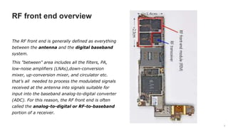
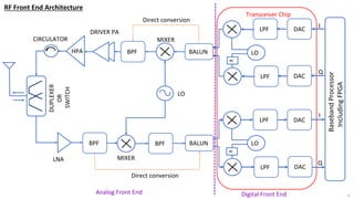
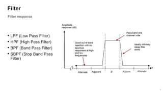
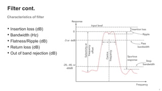
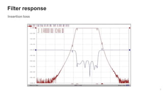
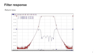
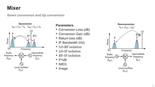
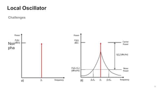
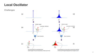
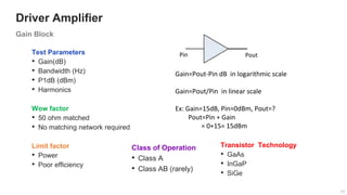
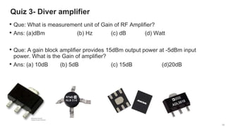
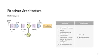
Analog RF Front End Architecture
Shiv Dutt
RF Product Design Engineer (H/W)
Basic Blocks of RF for a generic RFFE Architecture
2
2
Contents
• RF Front end Overview
• Tx/Rx chain explanation
• Link budget calculation
• Receiver Architecture
3
3
RF front end overview
3
The RF front end is generally defined as everything
between the antenna and the digital baseband
system.
This "between" area includes all the filters, PA,
low-noise amplifiers (LNAs),down-conversion
mixer, up-conversion mixer, and circulator etc.
that’s all needed to process the modulated signals
received at the antenna into signals suitable for
input into the baseband analog-to-digital converter
(ADC). For this reason, the RF front end is often
called the analog-to-digital or RF-to-baseband
portion of a receiver.
4
4
4
Transceiver Chip
DAC
DAC
LPF
LPF
LO
90
BALUN
DAC
DAC
LPF
LPF
90
BALUN
Baseband
Processor
Including
FPGA
BPF
LO
BPF
BPF
DUPLEXER
OR
SWITCH
MIXER
LO
DRIVER PA
HPA
LNA
MIXER
Direct conversion
Direct conversion
RF Front End Architecture
Digital Front End
Analog Front End
I
I
Q
Q
CIRCULATOR
5
5
5
Filter
• LPF (Low Pass Filter)
• HPF (High Pass Filter)
• BPF (Band Pass Filter)
• SBPF (Stop Band Pass
Filter)
5
6
6
6
Filter cont.
• Insertion loss (dB)
• Bandwidth (Hz)
• Flatness/Ripple (dB)
• Return loss (dB)
• Out of band rejection (dB)
6
7
Filter response
7
8
8
Filter response
8
9
9
Quiz 1- Filter
• Que: which return loss is better ?
• Ans: (a) -20dB (b) -15dB (c) -40dB (d) -8dB
• Que: what is unit of filter bandwidth
• Ans: (a) MHz (b) Hz (c) dB (d) a and b both
9
10
10
Mixer
Parameters
• Conversion Loss (dB)
• Conversion Gain (dB)
• Return loss (dB)
• IF Bandwidth (Hz)
• LO-RF isolation
• LO-IF isolation
• RF-IF isolation
• P1dB
• IMD3
• Image
10
11
11
Mixer cont.
1.LO power
should be at least
20dB higher than
RF Power.
2.1dB
compression
point typically 10
dB lower than LO
Power.
11
12
12
Quiz 2- Mixer
12
• Que: In the up-conversion, which is true
• Ans: (a)RF=LO-IF (b) RF=LO+IF (c) IF=LO-RF(d) a and b both
• Que: If a mixer has 15dBm LO power, what should be the p1dB
compression point?
• Ans: (a) 10dbm (b) 5dBm (c) 15dBm (d)12dBm
13
13
Local Oscillator
13
PLL Synthesizer Basic Building Blocks
• Phase-Frequency Detector (PFD)
• Reference Counter (R)
• Feedback Counter (N)
• The Phase-Frequency Detector (PFD)
14
14
Local Oscillator
14
Challenges
15
15
Local Oscillator
15
Noise in Oscillator Systems-
phase noise
Challenges
16
16
Local Oscillator
16
Challenges
17
17
17
Test Parameters
• Gain(dB)
• Bandwidth (Hz)
• P1dB (dBm)
• Harmonics
Wow factor
• 50 ohm matched
• No matching network required
Limit factor
• Power
• Poor efficiency
Pin Pout
Gain=Pout-Pin dB in logarithmic scale
Gain=Pout/Pin in linear scale
Ex: Gain=15dB, Pin=0dBm, Pout=?
Pout=Pin + Gain
= 0+15= 15dBm
Class of Operation
• Class A
• Class AB (rarely)
Transistor Technology
• GaAs
• InGaP
• SiGe
Driver Amplifier
Gain Block
18
18
Quiz 3- Diver amplifier
18
• Que: What is measurement unit of Gain of RF Amplifier?
• Ans: (a)dBm (b) Hz (c) dB (d) Watt
• Que: A gain block amplifier provides 15dBm output power at -5dBm input
power. What is the Gain of amplifier?
• Ans: (a) 10dB (b) 5dB (c) 15dB (d)20dB
19
19
Power Amplifier
19
Test Parameters
• Gain(dB)
• Bandwidth (Hz)
• P1dB (dBm)
• P3dB (dBm)
• Harmonics (dBm)
• PAE (%)
• IMD (dBm)
Wow factor
• High power available
Limit factor
• It required matching network
• Best tune for one parameter
• Oscillation tendency
Class of Operation
• Class A,B,AB,C,D,E and F
• Mixed class
Architecture
• Doherty PA
• Feedforward PA
Transistor Technology
• LDMOS
• GaN
• AlGaN
20
20
PA Parameter
• Gain=Pout –Pin ;in log scale, Gain=Pout/Pin ;in linear scale
• Bandwidth =amplification range from F1 to F2
Low power PA- broadband
High power PA- narrow band
• P1db Pout α Pin,  Pout=G*Pin  G=Pout-Pin
In linear operation when Pin increased, Pout increased by constant gain, after some time a point
comes where Gain starts to reduce and compressed by 1dB at certain Pout that point is called p1dB.
• P3db- Gain compressed by 3dB at certain Pout that point is called p3dB
• Harmonics (dBm)- integer multiple of fundamental frequency, n=1,2,3……….
• PAE(%) = (Pout-Pin/Pdc)*100=(Pout-Pin/(Vdd*Id))*100 ;power should be in linear
• IMD(dBm)= This is linearity test of PA, Two tones are to be feed to PA keeping specific
separation, as PA attains nonlinearity with increasing tones amplitude Intermodulation
occurs and generating other frequencies.
IMD=nF1+mF2 Where M & N are integers (can be positive or negative)
20
21
21
Quiz 4- Power Amplifier
21
© 2019-2020 Sterlite Technologies Limited
• Que: When PA attains p1db, which parameter get reduced at further input?
• Ans: (a)Harmonics (b) bandwidth (c) Gain (d) Efficiency
• Que: What is PAE of an amplifier?
• Ans: (a) (Pout/Pdc)*100
(b) (Pdc/Pin)*100
(c) ((Pout-Pin)/Pdc)*100
(d) ((Pin-Pout)/Pdc)*100
• Que: if F1=850 MHz is fundamental frequency of a PA, what will be 3rd harmonic?
• Ans: (a)850 MHz (b) 1700MHz (c) 2550 MHz (d) 425MHz
22
22
23
23
24
24
25
25
Quiz 5- Circulator/Duplexer
25
• Que: A circulator is known as isolator, if third port except through port is terminated with
following termination resistor ?
• Ans: (a)75 Ohm (b) 50 Ohm (c) 100 Ohm (d) 50k Ohm
• Que: which front end component is used in TDD system?
• Ans: (a) Duplexer (b) SPDT switch (c) Circulator (d) b and c both
• Que: which front end component is used in FDD system?
• Ans: (a) Duplexer (b) SPDT switch (c) Circulator (d) a and c both
• Que: Suppose 10Watt average power is transmitting at antenna port of a radio, what
should be the peak handling power of SPDT switch for a normal operation?
• Ans: (a)10Watt (b) 20Watt (c) 5Watt (d) 50watt
26
26
Rx Chain
26
27
27
28
28
29
29
Quiz 6- LNA
29
• Que: A band pass filter has 1dB insertion loss, what is the Noise figure?
• Ans: (a)3 dB (b) 2dB (c) 0 dB (d) 1dB
• Que: A LNA has input of -30dBm with noise power of -40dBm, what is the SNR?
• Ans: (a) -70dB (b) 70dB (c) -10dB (d) 10dB
• Que: A LNA has SNRin=10dB and SNRout=6dB, what is noise figure of LNA
• Ans: (a) 2.2dB (b) 4dB (c) 6dB (d) 10dB
• Que: there are two LNA in Rx chain in cascaded, NF1=1dB, G1=10dB, NF2=3dB,
G2=20dB, what is total equivalent Noise figure?
• Ans: (a) 1.3dB (b) 1dB (c) 1.2dB (d) 3dB
30
30
31
31
32
32
33
33
34
34
Quiz 7- Link Budget
34
• Que1: PA1 has 10dB gain and p1dB of 25dBm, if RF input is 20dBm what is
output power?
• Ans: (a)25dBm (b) 30dBm (c) 10dBm (d) slightly greater than
25dBm
• Que2: PA1 has 10dB gain and p1dB of 25dBm, PA2 has 10dB gain and
p1dB of 30dBm, if RF input is 10dBm what is output power of PA2?
• Ans: (a) 20dBm (b) 30dBm (c) 25dBm (d) 10dBm
• Que3: A circulator of insertion loss 0.5dB has been planned at the output of
PA2 in Que2, what is the output power now?
• Ans: (a) 20dBm (b) 30dBm (c) 29.5dBm (d) 10dBm
35
35
36
36
37
37
38
39
39
39
Thankyou
https://www.slideshare.net/SHIVDUTT3/edit_my_uploads

Analog RF Front End Architecture

  • 1.
    Analog RF FrontEnd Architecture Shiv Dutt RF Product Design Engineer (H/W) Basic Blocks of RF for a generic RFFE Architecture
  • 2.
    2 2 Contents • RF Frontend Overview • Tx/Rx chain explanation • Link budget calculation • Receiver Architecture
  • 3.
    3 3 RF front endoverview 3 The RF front end is generally defined as everything between the antenna and the digital baseband system. This "between" area includes all the filters, PA, low-noise amplifiers (LNAs),down-conversion mixer, up-conversion mixer, and circulator etc. that’s all needed to process the modulated signals received at the antenna into signals suitable for input into the baseband analog-to-digital converter (ADC). For this reason, the RF front end is often called the analog-to-digital or RF-to-baseband portion of a receiver.
  • 4.
  • 5.
    5 5 5 Filter • LPF (LowPass Filter) • HPF (High Pass Filter) • BPF (Band Pass Filter) • SBPF (Stop Band Pass Filter) 5
  • 6.
    6 6 6 Filter cont. • Insertionloss (dB) • Bandwidth (Hz) • Flatness/Ripple (dB) • Return loss (dB) • Out of band rejection (dB) 6
  • 7.
  • 8.
  • 9.
    9 9 Quiz 1- Filter •Que: which return loss is better ? • Ans: (a) -20dB (b) -15dB (c) -40dB (d) -8dB • Que: what is unit of filter bandwidth • Ans: (a) MHz (b) Hz (c) dB (d) a and b both 9
  • 10.
    10 10 Mixer Parameters • Conversion Loss(dB) • Conversion Gain (dB) • Return loss (dB) • IF Bandwidth (Hz) • LO-RF isolation • LO-IF isolation • RF-IF isolation • P1dB • IMD3 • Image 10
  • 11.
    11 11 Mixer cont. 1.LO power shouldbe at least 20dB higher than RF Power. 2.1dB compression point typically 10 dB lower than LO Power. 11
  • 12.
    12 12 Quiz 2- Mixer 12 •Que: In the up-conversion, which is true • Ans: (a)RF=LO-IF (b) RF=LO+IF (c) IF=LO-RF(d) a and b both • Que: If a mixer has 15dBm LO power, what should be the p1dB compression point? • Ans: (a) 10dbm (b) 5dBm (c) 15dBm (d)12dBm
  • 13.
    13 13 Local Oscillator 13 PLL SynthesizerBasic Building Blocks • Phase-Frequency Detector (PFD) • Reference Counter (R) • Feedback Counter (N) • The Phase-Frequency Detector (PFD)
  • 14.
  • 15.
    15 15 Local Oscillator 15 Noise inOscillator Systems- phase noise Challenges
  • 16.
  • 17.
    17 17 17 Test Parameters • Gain(dB) •Bandwidth (Hz) • P1dB (dBm) • Harmonics Wow factor • 50 ohm matched • No matching network required Limit factor • Power • Poor efficiency Pin Pout Gain=Pout-Pin dB in logarithmic scale Gain=Pout/Pin in linear scale Ex: Gain=15dB, Pin=0dBm, Pout=? Pout=Pin + Gain = 0+15= 15dBm Class of Operation • Class A • Class AB (rarely) Transistor Technology • GaAs • InGaP • SiGe Driver Amplifier Gain Block
  • 18.
    18 18 Quiz 3- Diveramplifier 18 • Que: What is measurement unit of Gain of RF Amplifier? • Ans: (a)dBm (b) Hz (c) dB (d) Watt • Que: A gain block amplifier provides 15dBm output power at -5dBm input power. What is the Gain of amplifier? • Ans: (a) 10dB (b) 5dB (c) 15dB (d)20dB
  • 19.
    19 19 Power Amplifier 19 Test Parameters •Gain(dB) • Bandwidth (Hz) • P1dB (dBm) • P3dB (dBm) • Harmonics (dBm) • PAE (%) • IMD (dBm) Wow factor • High power available Limit factor • It required matching network • Best tune for one parameter • Oscillation tendency Class of Operation • Class A,B,AB,C,D,E and F • Mixed class Architecture • Doherty PA • Feedforward PA Transistor Technology • LDMOS • GaN • AlGaN
  • 20.
    20 20 PA Parameter • Gain=Pout–Pin ;in log scale, Gain=Pout/Pin ;in linear scale • Bandwidth =amplification range from F1 to F2 Low power PA- broadband High power PA- narrow band • P1db Pout α Pin,  Pout=G*Pin  G=Pout-Pin In linear operation when Pin increased, Pout increased by constant gain, after some time a point comes where Gain starts to reduce and compressed by 1dB at certain Pout that point is called p1dB. • P3db- Gain compressed by 3dB at certain Pout that point is called p3dB • Harmonics (dBm)- integer multiple of fundamental frequency, n=1,2,3………. • PAE(%) = (Pout-Pin/Pdc)*100=(Pout-Pin/(Vdd*Id))*100 ;power should be in linear • IMD(dBm)= This is linearity test of PA, Two tones are to be feed to PA keeping specific separation, as PA attains nonlinearity with increasing tones amplitude Intermodulation occurs and generating other frequencies. IMD=nF1+mF2 Where M & N are integers (can be positive or negative) 20
  • 21.
    21 21 Quiz 4- PowerAmplifier 21 © 2019-2020 Sterlite Technologies Limited • Que: When PA attains p1db, which parameter get reduced at further input? • Ans: (a)Harmonics (b) bandwidth (c) Gain (d) Efficiency • Que: What is PAE of an amplifier? • Ans: (a) (Pout/Pdc)*100 (b) (Pdc/Pin)*100 (c) ((Pout-Pin)/Pdc)*100 (d) ((Pin-Pout)/Pdc)*100 • Que: if F1=850 MHz is fundamental frequency of a PA, what will be 3rd harmonic? • Ans: (a)850 MHz (b) 1700MHz (c) 2550 MHz (d) 425MHz
  • 22.
  • 23.
  • 24.
  • 25.
    25 25 Quiz 5- Circulator/Duplexer 25 •Que: A circulator is known as isolator, if third port except through port is terminated with following termination resistor ? • Ans: (a)75 Ohm (b) 50 Ohm (c) 100 Ohm (d) 50k Ohm • Que: which front end component is used in TDD system? • Ans: (a) Duplexer (b) SPDT switch (c) Circulator (d) b and c both • Que: which front end component is used in FDD system? • Ans: (a) Duplexer (b) SPDT switch (c) Circulator (d) a and c both • Que: Suppose 10Watt average power is transmitting at antenna port of a radio, what should be the peak handling power of SPDT switch for a normal operation? • Ans: (a)10Watt (b) 20Watt (c) 5Watt (d) 50watt
  • 26.
  • 27.
  • 28.
  • 29.
    29 29 Quiz 6- LNA 29 •Que: A band pass filter has 1dB insertion loss, what is the Noise figure? • Ans: (a)3 dB (b) 2dB (c) 0 dB (d) 1dB • Que: A LNA has input of -30dBm with noise power of -40dBm, what is the SNR? • Ans: (a) -70dB (b) 70dB (c) -10dB (d) 10dB • Que: A LNA has SNRin=10dB and SNRout=6dB, what is noise figure of LNA • Ans: (a) 2.2dB (b) 4dB (c) 6dB (d) 10dB • Que: there are two LNA in Rx chain in cascaded, NF1=1dB, G1=10dB, NF2=3dB, G2=20dB, what is total equivalent Noise figure? • Ans: (a) 1.3dB (b) 1dB (c) 1.2dB (d) 3dB
  • 30.
  • 31.
  • 32.
  • 33.
  • 34.
    34 34 Quiz 7- LinkBudget 34 • Que1: PA1 has 10dB gain and p1dB of 25dBm, if RF input is 20dBm what is output power? • Ans: (a)25dBm (b) 30dBm (c) 10dBm (d) slightly greater than 25dBm • Que2: PA1 has 10dB gain and p1dB of 25dBm, PA2 has 10dB gain and p1dB of 30dBm, if RF input is 10dBm what is output power of PA2? • Ans: (a) 20dBm (b) 30dBm (c) 25dBm (d) 10dBm • Que3: A circulator of insertion loss 0.5dB has been planned at the output of PA2 in Que2, what is the output power now? • Ans: (a) 20dBm (b) 30dBm (c) 29.5dBm (d) 10dBm
  • 35.
  • 36.
  • 37.
  • 38.
  • 39.