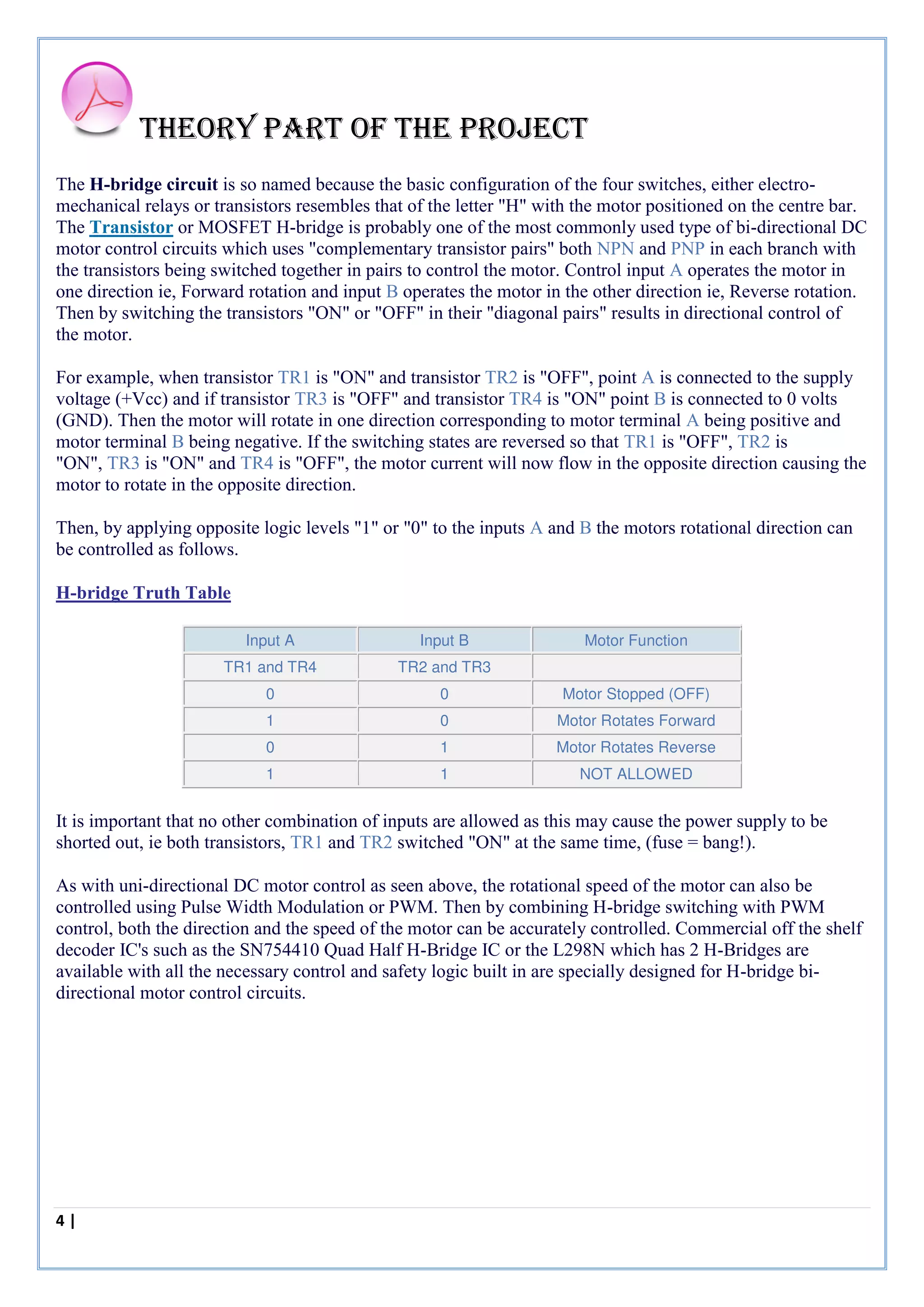
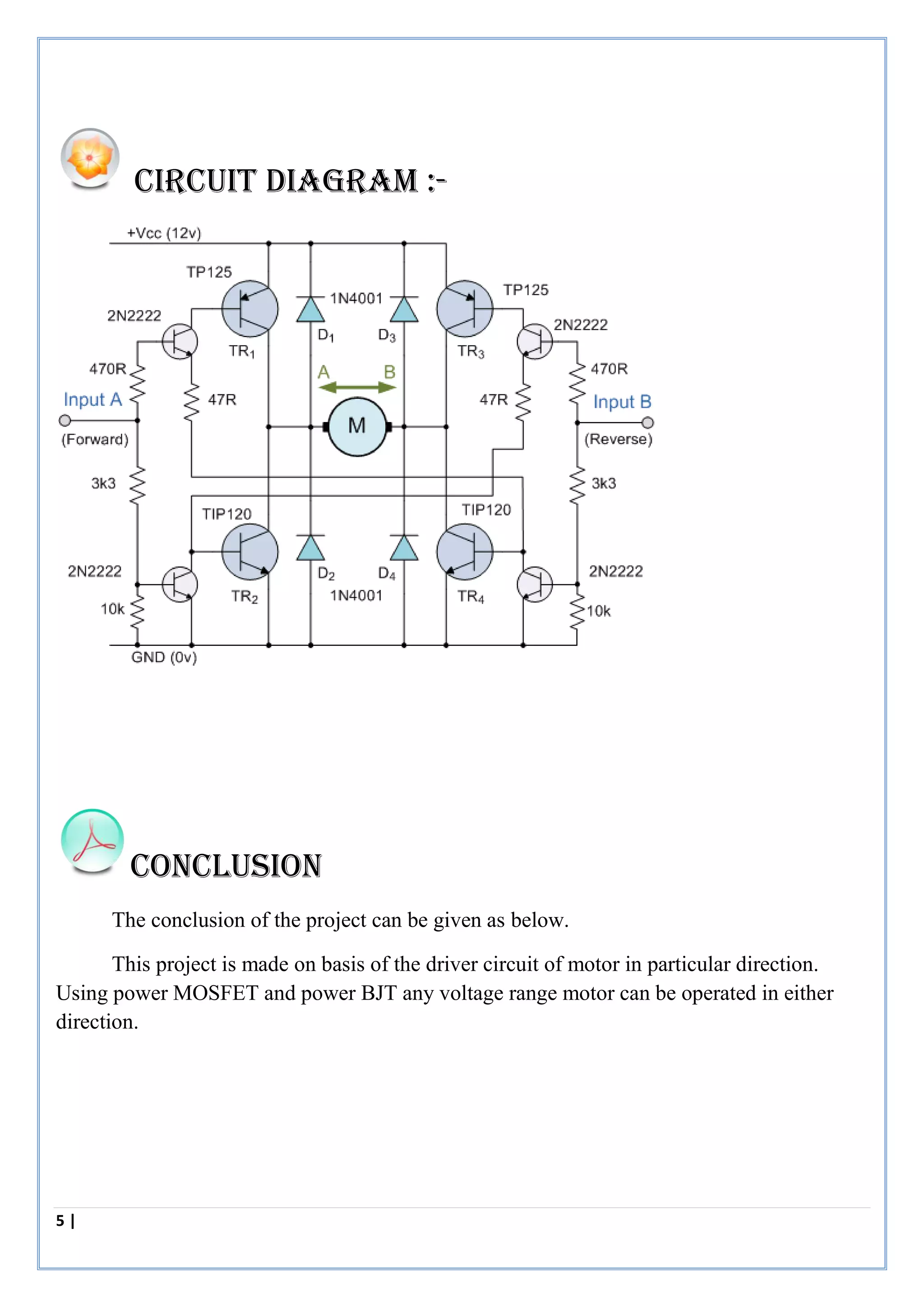
This project is made on basis of the driver circuit of motor in particular direction. Using power MOSFET and power BJT any voltage range motor can be operated in either direction.
The document discusses an H-bridge circuit used to control DC motors. An H-bridge uses four transistors arranged in a bridge configuration to allow reversing polarity of a motor. It explains that H-bridges are used in robotics to control motor direction. The key components and operation are described, including how different transistor states result in motor rotation, braking or free spinning. Implementing an H-bridge circuit with transistors on a breadboard is recommended to learn how it works in practice.
An H bridge is an electronic circuit that allows the direction of current flowing through a motor to be reversed. It contains four switches that can be opened and closed in different combinations to determine the direction of current flow. H bridges are commonly used in robotics and other applications to allow DC motors to run forwards and backwards. They can also be used to brake or disconnect a motor. H bridges can be constructed from discrete components or integrated circuits and are often used in motor control circuits.
Here is the description of motor driver IC. How does it work ?
Pin description and functionality and working process is presented. Interfacing of L293D with arduino UNO board.
The document presents information on the Motor Driver IC L293D. It begins with an introduction of the topic and importance of topic presentations. It then provides details on the L293D including what it is, its pin descriptions, circuit diagram, working procedures, description of an H-bridge, and applications. The L293D is an integrated circuit used to control the direction and speed of two DC motors simultaneously up to 36V and 600mA. It works by using an H-bridge circuit configuration to allow controlling the direction of current and voltage applied to the motor. Applications mentioned include controlling robots.
This document discusses different types of actuators used in robotics including rotational actuators like DC motors and stepper motors, and linear actuators like pneumatics and artificial muscles. It focuses on DC motors and geared motors, explaining their operation and benefits. It also covers motor drivers, comparing electromechanical drivers using relays to solid-state drivers using transistors. H-bridge motor drivers are described in detail as they allow controlling motor direction. Integrated h-bridge ICs are also mentioned.
An H-bridge circuit allows voltage to be applied across a motor in either direction, enabling full control over the motor's direction and speed. It is commonly used with a motor driver integrated circuit like the L293D or L298, which contains H-bridge components and can switch higher motor currents than a microcontroller alone. These ICs act as switches to control two DC motors independently according to the logic applied to their inputs.
The L298 Driver is a high voltage, high current dual ful bridge driver designed to accept standard TTL logic levels and drive inductive loads such relays, solenoids, DC and stepping motors. Two enable inputs are provided to enable or disable the device independently of the input signals. The emitters of the lower transistors of each bridge are connected together the corresponding external terminal can be used for the connection of an external sensing resistor.
Motor Control Relay, Pwm, DC and Stepper MotorsDevashish Raval
In this presentation, a brief introduction of relay, optoisolaters, interfacing and working of stepper motor and DC motor is given.
The contents are referred from the book of mazidi.
Dc motor interfacing with 8051 microcontrollerUmar Shuaib
The document discusses two methods for interfacing a DC motor with an 8051 microcontroller: using an L293 motor driver IC or building an H-bridge circuit. The L293 is a dedicated motor driver IC that provides high current capacity and protection from voltage spikes. It requires only 3 pins from the microcontroller to control the motor's direction. An H-bridge circuit uses four transistors in a bridge configuration to reverse the motor's polarity and change rotation directions by controlling the transistors with two pins from the microcontroller. Both methods allow the microcontroller to control the DC motor bidirectionally while protecting the microcontroller.
In this project we will be controlling the speed of Dc motor using Arduino controller. Dc motor is drive by using PWM technique and then using encoder to sense the rpm of DC motor. Encoder produces pulses in the output, which is feed into Arduino and Arduino controls the speed of DC motor. So we have implemented the feedback system which controls the speed of DC motor.
DC Motor Direction Control Using 8051 C ProgramDinesh Damodar
this ppt illustrates the interfacing of 8051 microcontrollers and DC motor. Here we had undertaken Simple geared DC motor as a subject to control, using 8051. 8051 is considered since it is an entrance of basics in learning microcontrollers
This document presents information about the L293D motor driver integrated circuit. It includes sections on what an L293D is, describing it as an IC that can control two DC motors simultaneously. It also covers the pin descriptions of the L293D, its circuit diagram, working procedures including how it enables motor direction, a description of an H-bridge circuit, and applications of the L293D such as in robots.
Speed Control of DC motor using AT89C52 ICDisha Modi
This document describes a project to control the speed of a DC motor using pulse width modulation (PWM) generated by an AT89C52 microcontroller. The document outlines the purpose, components, circuit diagram, programming, and workflow. Key components include an AT89C52 microcontroller, L293D motor driver, DC motor, voltage regulator, and buttons. PWM signals of varying duty cycles control the motor's speed. Code uses timers to generate PWM and buttons to select speed. The summary provides an overview of the goal and approach.
SPEED CONTROL OF SEPARATELY EXCITED DC MOTOR USING POWER ELECTRONIC CONVERTER ijiert bestjournal
In a modern technology the use of power electronic devices in the control strategies of
electrical drives is increasing. The speed of a DC motor can be varied by controlling the field
flux, the armature resistance or the terminal voltage applied to the armature circuit. The three
most common speed control methods are field resistance control, armature voltage control,
and armature resistance control. But here a technique of drive has been used for DC motor’s
speed control is chopper and some power electronics devices. It has been shown here the use
of chopper and power electronics devices which paves the way of controlling also torque and
speed characteristics of DC motor. Now the simulation of model is done and analysed in
MATLAB (Simulink) under varying speed and torque condition
This document discusses how to connect and control a DC motor using an Arduino Uno board. It explains the components needed like the motor, MOSFET transistor, diode rectifier and resistor. It describes how the motor works using electromagnetic principles and how the diode rectifier converts AC to DC power. It shows the pin connections and provides an example Arduino code using PWM to control the motor's speed by writing analog values to the motor control pin.
Electromagnetic relays are classified based on technology and function. An attracted armature relay uses electromagnetic force and is fast acting, making it suitable for protection applications. Relays respond to electrical quantities like voltage, current, frequency, and phase angle. A polarized relay only operates based on the direction of current or voltage. Burden refers to the power consumed by a relay. Static relays offer advantages over electromagnetic relays like lower power consumption and compact size.
Seperation of losses in three phase induction motorarikesh
This document provides instructions to separate the losses in a three-phase induction motor. It lists the required apparatus, describes the theory behind separating core and friction/windage losses through a no-load test at variable voltages, outlines the procedure to conduct the test, and explains how to calculate losses by plotting no-load power versus voltage and extrapolating to zero voltage. Measurements of stator resistance and calculations of copper loss are also described to fully separate motor losses.
Abstract
This report focuses on controlling the speed of a DC motor using PWM technique.
Direct current (DC) motors have been widely used in many industrial applications such as electric vehicles, steel rolling mills, electric cranes, and robotic manipulators due to precise, wide, simple, and continuous control characteristics
The dc motor speed in general is directly proportional to the supply voltage, so if reduce the voltage from 12 volts to 6 volts then our speed become half of what it originally had. But in practice, for changing the speed of a dc motor we cannot go on changing the supply voltage all the time. Rather than simply adjusting the voltage sent to the motor, we can switch the motor supply on and off where switching is done so much fast that the motor only notices the average voltage effect and not the switching operation.
This document describes a project to control the speed of a single-phase induction motor using a TRIAC. It includes sections on the circuit description, induction motor working, SCR, TRIAC, DIAC, applications, advantages and disadvantages. The circuit uses a DIAC to trigger a TRIAC, allowing control of the firing angle to vary the voltage applied to the motor. This provides speed control of the induction motor for applications like pumps, fans and refrigeration.
This document is a report on an internship at ABB in Nashik submitted by Amol Nanaji Bagul. It includes an acknowledgements section thanking those who helped with the internship. The document then covers topics related to vacuum circuit breakers and vacuum contactors, including their construction, operating principles, testing procedures, and applications. Sections describe key components like vacuum interrupters, operating mechanisms, and control circuits. Maintenance and servicing are also discussed.
This document discusses different methods of controlling the speed of DC motors, focusing on pulse width modulation (PWM). PWM works by rapidly switching the voltage to the motor on and off to vary the average power and control motor speed. A higher duty cycle (proportion of time the voltage is on) results in a higher average voltage and faster motor speed. Examples are provided of calculating duty cycles and switching frequencies for different speed control applications.
Doc speed control of a dc motor using micro controller 8051embdnew
This document describes a project to control the speed of a DC motor using pulse width modulation (PWM) generated by a microcontroller. A group of four students developed the project under a professor's supervision. PWM pulses are generated by an 8051 microcontroller to vary the motor speed by changing the duty cycle. The project aims to provide a reliable and efficient method of DC motor speed control.
This document describes a project report on a DC motor controller using an 89C51 microcontroller. It was submitted by three students to fulfill requirements for their engineering degree. The project involved designing a circuit to control a DC motor interfaced with a driver circuit using an 89C51 microcontroller. It also included constructing a prototype solar cell movement system and an emergency light inverter circuit to operate lights from a battery charged by the solar panel.
MATLAB Simulation on Speed Control of Four Quadrant DC Drive Using ChopperADARSH KUMAR
MATLAB Simulation on Speed Control of Four Quadrant DC Drive Using Chopper
Abstract - This paper deals with the speed of dc motor can be control by using chopper is to designed the four quadrant speed control model. the speed control of dc motor provide designed model for four quadrant in both direction i.e. clockwise direction, counter clockwise direction along with braking of the dc motor .this operation will not superior than ac motor , compare with dc motor because the ac motor changing the rotation of motor is unmanageable and complicated to design as compared with the dc motor. Therefore for the smooth in operation we can used the insulate gate bipolar transistor (IGBT). For speed control of dc motor in both direction the chopper circuit is designed by using IGBT. The pulse width modulation (PWM) is used foe switching operation of IGBT. The PWM designed signal model can be generated by using IC LM324 (quart op-amp). To control the direction and the speed of motor, the four quadrant speed control technique is not a complicated
El L293D es un circuito integrado que permite controlar motores de corriente continua de hasta 1 amperio. Contiene cuatro puentes en H que actúan como conmutadores bidireccionales para controlar el giro y la velocidad de los motores. Se activan por pares mediante señales TTL de habilitación y cuentan con protecciones como diodos incorporados para una alta corriente de salida de forma segura.
The document discusses the L293D motor driver IC, which contains four half-H bridges that can be used to bidirectionally control two DC motors. It provides up to 600 mA of current to each motor and is interfaced with a microcontroller through four input pins to control the direction and speed of two motors independently.
The L293 and L293D are integrated circuits that provide bidirectional current of up to 1A and 0.6A respectively to drive devices such as motors and solenoids. They have separate voltage supply inputs for logic and power, with a range of 4.5V to 36V. Each device has four driver channels that are paired and enabled together, with internal diode protection for inductive loads.
This document summarizes information about analog to digital converters (ADCs). It discusses the differences between analog and digital signals, examples of ADC applications like microphones and thermocouples, and the main types of ADCs - dual slope, successive approximation, flash, and delta-sigma. For successive approximation ADCs, it describes how a successive approximation register tries different bit values to convert the analog input signal into a digital output. The document was prepared by electrical engineering students for a course assignment.
1. Analog to digital conversion takes place in 3 steps: sampling, quantization, and code word generation.
2. Sampling measures the amplitude of a signal at equal intervals and converts it to a discrete time signal. Quantization rounds the signal to the nearest finite level. Code word generation converts the signal into binary form.
3. Higher sample rates and bit depths allow analog waveforms to be more closely matched in digital format, improving quality. But higher frequencies require higher sample rates to accurately capture the shape of the wave.
The document discusses the 8051 microcontroller, its features, and applications. It provides details on the 8051's architecture including its CPU, memory blocks, I/O ports, timers/counters, and serial communication capabilities. It describes the 8051's registers including TMOD and TCON for timer control. The document also covers the 8051's memory mapping and provides many examples of how 8051 microcontrollers are used in applications like cell phones, appliances, industrial systems, and more.
The document discusses the Microcontroller 8051. It provides a block diagram and pin description of the 8051. It describes the registers, memory mapping, stack, I/O ports, timers and interrupts of the 8051 microcontroller. It compares microprocessors and microcontrollers, discussing the differences in hardware structure and applications.
The document discusses DC motors. It describes 3 types of DC motors - shunt motors, series motors, and compound motors. It explains the construction and working principles of each type. Speed control methods for DC motors are also discussed, including flux control, armature control, and voltage control. Various applications of each DC motor type are provided.
Microcontroller 8051 and its interfacingAnkur Mahajan
The document discusses microcontrollers and interfacing. It begins with definitions of microprocessors and microcontrollers, comparing their differences. It then focuses on the 8051 microcontroller, describing its features, block diagram, manufacturers, and addressing modes. The document outlines how to write programs for the 8051 and discusses real-world interfacing examples like LCDs, ADCs, relays, motors. It concludes with applications of the 8051 and contact information.
1. A DC motor runs on direct current electricity. It has a field winding that produces a magnetic field when energized, and an armature winding that rotates when placed in this magnetic field.
2. The key parts of a DC motor include the yoke, poles, field winding, armature core, armature winding, commutator, and brushes. The field winding produces flux, and the rotation of the armature winding within this flux induces voltage that is used to power the load.
3. DC motors can be shunt wound, series wound, or compound wound depending on how the field and armature windings are connected. Shunt and series motors have different torque-speed characteristics due
The document discusses different types of analog to digital converters (ADCs). It begins by defining analog and digital signals and the basic principle of an ADC which uses a comparator to determine binary output bits. It then discusses three main ADC types: flash ADCs which use multiple comparators, dual slope/counter ADCs which use a capacitor and counter, and successive approximation ADCs which use feedback to iteratively approximate the analog value. It compares the resolution, speed and cost of different ADC types and gives examples of ADC applications.
The document describes experiments on electric drive systems in the Electrical Department lab at JIS College of Engineering. The 10 listed experiments include:
1. Studying thyristor controlled DC drives and chopper fed DC drives.
2. Studying AC single phase motor speed control using a TRIAC.
3. Studying PWM inverter fed 3-phase induction motor control using software.
The document provides theory, circuit diagrams, and procedures for each experiment. It describes using equipment like thyristors, choppers, inverters, motors, and software to control motor speed and study electric drive systems.
Review on Speed and Direction Control of DC Motor By using Single MOSFET and ...IRJET Journal
This document describes a circuit design for controlling the speed and direction of a DC motor using a single MOSFET and two SPDT relays.
Traditionally, an H-bridge circuit with four switches is used to control DC motor speed and direction. The proposed circuit aims to simplify this design by using a single MOSFET controlled by pulse-width modulation to vary motor speed, and two SPDT relays controlled by separate signals to select motor direction.
The document outlines the circuit schematic, operating principles, control logic, and advantages of the proposed design. It claims the design offers improvements over traditional H-bridge circuits in terms of lower cost, simpler design, reduced component count, and greater reliability.
A Single Switch High Gain Coupled Inductor Boost ConverterIRJET Journal
This document summarizes a research paper on a single switch high gain coupled inductor boost converter with closed loop control and low switch voltage stress. The proposed converter uses a coupled inductor and passive clamp network to achieve high voltage gain without high duty cycles. This prevents problems like reverse recovery and reduces switch voltage stress. Simulation results show the converter operates with a 40V input and 400V/400W output at 50kHz switching frequency using optimized component values determined through design calculations.
Single Phase Thirteen-Level Inverter using Seven Switches for Photovoltaic sy...Editor IJMTER
This paper proposes a single-phase thirteen-level inverter using seven switches, with a
novel pulse width-modulated (PWM) control scheme. The Proposed multilevel inverter output
voltage level increasing by using less number of switches driven by the multicarrier modulation
techniques. The inverter is capable of producing thirteen levels of output-voltage (Vdc, 5/6Vdc,
4/6Vdc, 3/6Vdc, 2/6Vdc, 1/6Vdc, 0, -5/6Vdc, -4/6Vdc, -3/6Vdc, -2/6Vdc, -1/6Vdc,-Vdc) from the
dc supply voltage. A digital multi carrier PWM algorithm was implemented in a Spartan 3E FPGA.
The proposed system was verified through simulation and implemented in a prototype.
Design and Control of Half-Bridge Resonant Converter Topology of PID ControllerIRJET Journal
This document discusses the design and control of a half-bridge resonant converter topology using a PID controller. It describes how a closed loop LLC resonant DC-DC half-bridge converter with a PID controller can provide constant output voltage for both linear and non-linear loads. The converter is simulated in MATLAB/Simulink and the hardware is tested, showing high efficiency of 95% and constant output voltage regulation. Key aspects of the half-bridge resonant converter such as the resonant tank circuit and soft switching operation are explained.
1.SINGLE PHASE HALF WAVE CONTROLLED CONVERTER WITH RESISTIVEINDUCTIVE LOAD
2 SINGLE PHASE FULLY CONTROLLED CONVERTER WITH RESISTIVEINDUCTIVE LOAD
3 SPEED CONTROL OF 3-PHASE SLIP RING (WOUND ROTOR) INDUCTION MOTOR
4 THYRISTORISED DRIVE FOR DC MOTOR WITH CLOSED LOOP CONTROL
5 THYRISTORISED DRIVE FOR PMDC MOTOR WITH SPEED MEASUREMENT & CLOSED LOOP CONTROL
6 SPEED MEASUREMENT OF PMDC MOTOR WITH CLOSED LOOP CONTROL
7 IGBT USING SINGLE 4 QUADRANT CHOPPER DRIVE FOR PMDC MOTOR WITH SPEED MEASUREMENT AND CLOSED LOOP AND CONTROL
8 SINGLE PHASE CYCLO CONVERTER BASED AC INDUCTION MOTOR CONTROLLER
9 THREE PHASE INPUT THYRISTORISED DRIVE 3HP DC MOTOR WITH CLOSED LOOP CONTROL
10 THREE PHASE INPUT IGBT DRIVE FOR 4 QUADRANT CHOPPER OF 3HP DC MOTOR WITH CLOSED LOOP CONTROL
This document describes a project to create a tongue-driven wheelchair control system using a microcontroller. It includes 4 chapters: an introduction describing the motivation and components of the project, hardware components including sensors, a microcontroller and motor driver, software components including analog-to-digital conversion and pulse-width modulation algorithms, and conclusions. The system is intended to provide independent mobility for people with severe disabilities by detecting tongue motion with magnetic sensors and using the signals to control a powered wheelchair.
Asymmetrical Nine-level Inverter Topology with Reduce Power Semicondutor DevicesTELKOMNIKA JOURNAL
In this paper a new single-phase multilevel inverter topology is presented. Proposed topology is
capable of producing nine-level output voltage with reduce device counts. It can be achieved by arranging
available switches and dc sources in a fashion such that the maximum combination of addition and
subtraction of the input dc sources can be obtained. To verify the viability of the proposed topology, the
circuit model is developed and simulated in Matlab-Simulink software. Experimental testing results of the
proposed nine-level inverter topology, developed in the laboratory, are presented. A low frequency
switching strategy is employed in this work. The results show that the proposed topology is capable to
produce a nine-level output voltage, capable in handling inductive load and yields acceptable harmonic
distortion content.
Review on Automatic Power Factor Improvement of Induction MotorIRJET Journal
This document provides a review of techniques for automatic power factor improvement of induction motors. It begins with an abstract discussing the purpose of designing new techniques for power factor improvement in 3-phase and single-phase induction motors. The document then reviews the various components involved in an automatic power factor improvement system using a microcontroller, including the power supply, zero crossing detectors, microcontroller, electromagnetic relays, LCD display, capacitor bank, and software details. It concludes that power factor correction techniques can make power systems more stable and efficient while reducing costs when using a microcontroller.
IRJET- A Dual Stage Flyback Converter using VC MethodIRJET Journal
This document describes a dual stage flyback converter that uses voltage control (VC) method. It consists of two flyback converters operated alternately using a PI controller. The PI controller compares the reference voltage to the feedback voltage and compensates for errors. The output of the PI controller is compared to a triangular wave to generate driving signals for synchronous rectifiers in the two converters with 180 degree phase shift. This allows reducing additional freewheeling power. The converter is simulated in MATLAB Simulink. The simulation results show it can maintain the output voltage at 35V even when a 5V disturbance is added to the 24V input voltage, demonstrating the effectiveness of the closed-loop control strategy.
International Journal of Engineering Research and Applications (IJERA) is an open access online peer reviewed international journal that publishes research and review articles in the fields of Computer Science, Neural Networks, Electrical Engineering, Software Engineering, Information Technology, Mechanical Engineering, Chemical Engineering, Plastic Engineering, Food Technology, Textile Engineering, Nano Technology & science, Power Electronics, Electronics & Communication Engineering, Computational mathematics, Image processing, Civil Engineering, Structural Engineering, Environmental Engineering, VLSI Testing & Low Power VLSI Design etc.
IRJET- Design and Implementation of Isolated Multi-Output Flyback ConverterIRJET Journal
This document describes the design and implementation of an isolated multi-output flyback converter. A flyback converter uses a single switch and transformer to provide isolated output voltages from an input source. The designed converter uses a toroidal transformer with multiple secondary windings to generate multiple isolated output voltages at fixed levels. Simulation results and specifications for the transformer, switch, and outputs are provided. The flyback converter provides an efficient and low-cost solution for applications requiring multiple isolated low-power DC outputs.
BIDIRECTIONAL SPEED CONTROL OF DC MOTOR USING 8051 MICROCONTROLLERShanmukha S. Potti
1. This project deals with bidirectional speed control of DC motor using 8051 micro-controller.
2. Design of H bridge dc-dc converter is an IGBT based bridge circuit.
3. The control circuit consists of the 8051 microcontroller which is programmed to generate pulses to turn on IGBTs per required sequence.
4. The H bridge dc-dc converter is implemented with hardware setup and software program in the 8051 –C code.
This document describes an AC to AC step down cycloconverter that uses SCRs and an Arduino microcontroller to control the speed of an induction motor in three steps (full speed, half speed, and one-third speed). A cycloconverter can change the frequency of AC power without an intermediate DC link. This single-stage cycloconverter has two full-wave thyristor bridges connected back-to-back to produce an output frequency lower than the input frequency. The Arduino receives signals from slide switches to select the motor speed and triggers the appropriate SCRs to achieve speed control in three steps. MATLAB simulations show the output waveforms at different speeds. Pseudocode is provided for the Arduino program.
Comparator holds a dominant place in fast ADC circuit for the conversion of analog to digital signal. In this modernized digital world every utilization circuits requires an ADC’s with low power to consumption. This in turn reflects in the design of comparators during the design process of the fast ADC circuits, scope is due to the higher number of comparator usage. As the technologies are scaling down, the number of transistor per unit area increases, so that the sub threshold leakage current increases which leads to power consumption in any circuit. This sources the project idea to design a comparator. It is presumed during the design that, it consumes low power in its double tail configuration which when replaces an inverter circuit in latch stage of the double tail comparator by a sleepy inverter. This presumption is validated through the analysis of the simulation results. The power consumption of the designed proposed double tail comparator is 30μw when compared to 35 μw in the conventional type. 2-bit flash ADC circuit is designed and analyzed under two different configurations of the double tail comparator. From the results, it is clear that the power consumption of the ADC circuit designed with proposed sleepy inverter based double tail comparator is observed to be 45mw.
This document summarizes a student project report on analyzing a flyback converter. The project involved designing a simulation circuit for a flyback converter with an input of 12V DC and output of 240V DC. The report includes chapters on the operating principle, simulation, results, and conclusions. The key findings were that the flyback converter was able to step up the input voltage to the desired output level, and the output voltage, current, and input voltage waveforms were obtained through simulation as desired. The switching element used was a MOSFET due to its high power rating and switching speed.
This document presents a soft-switching two-switch resonant AC-DC converter that achieves high power factor and efficiency. The converter integrates a boost power factor correction circuit with a two-switch resonant converter. This allows it to achieve soft-switching, reduce component stress, and recycle energy stored in transformer leakage inductance. Simulation results show the converter achieves a power factor of 0.9 and soft-switching of the main switches and output diodes to reduce losses. The converter provides high efficiency power conversion with a simple control scheme.
This paper presents parameters analysis of 4-level capacitor-clamped boost converter with hard-switching and soft-switching implementation. Principally, by considering the selected circuit structure of the 4-level capacitor-clamped boost converter and appropriate pulse width modulation (PWM) switching strategy, the overall converter volume able to be reduced. Specifically, phase-shifted of 120° of each switching signal is applied in the 4-level capacitor-clamped boost converter in order to increase the inductor current ripple frequency, thus the charging and discharging times of the inductor is reduced. Besides, volume of converters is greatly reduced if very high switching frequency is considered. However, it causes increasing of semiconductor losses and consequently the converter efficiency is affected. The results show that the efficiency of 2-level conventional boost converter and 4-level capacitor-clamped boost converter are 98.59% and 97.67%, respectively in hard-switching technique, and 99.31% and 98.15%, respectively in soft-switching technique. Therefore, by applying soft-switching technique, switching loss of the semiconductor devices is greatly minimized although high switching frequency is applied. In this study, passive lossless snubber circuit is selected for the soft-switching implementation in the 4-level capacitor-clamped boost converter. Based on the simulation results, the switching loss is approximately eliminated by applying soft-switching technique compared to the hard-switching technique implementation.
This document discusses single phase and three phase inverters. It begins by defining an inverter as a device that converts DC power to AC power. It then describes different types of inverters including single phase half bridge and full bridge inverters as well as three phase inverters. The document explains the operating principles and switching sequences of these inverter types. It also discusses applications of inverters such as in motor drives, UPS systems, portable devices, power generation systems and more.
Single Stage Differential Folded Cascode AmplifierAalay Kapadia
The document presents the final report of a folded cascode amplifier design project. Key aspects of the design include:
1) The amplifier was designed to meet specifications including a gain of 85 dB, output swing of 1.4 V, and slew rate of 10 V/us.
2) A folded cascode topology was chosen to provide high output swing. Transistor sizes were calculated to meet the gain, slew rate, and output swing requirements.
3) Simulation results showed the design met all specifications, with an actual gain of 85.76 dB, phase margin of 60.1 degrees, and slew rate of 9.52 V/us.
Project Presentation :Analysis and characterization of different high density...Aalay Kapadia
For switched capacitor power converter (SCPC) designs at the power level below 100mW, if the capacitors can be integrated on‐chip, then the entire system can achieve monolithic implementation. This is very important for the applications requiring small system form factors. On‐chip capacitors can be implemented using high‐density capacitor technologies such as deep trench capacitors in IBM SOI processes. However, that will lead to high fabrication cost. With standard CMOS process, from the perspective of circuit designs (neither process, nor device), We are asked to suggest the most effective techniques to achieve high density on‐chip SCPC.
Analysis and characterization of different high density on chip switched capa...Aalay Kapadia
Power converter is a key component in micro-scale energy harvesting systems. Micro-scale energy harvesting has become an increasingly viable and promising area for powering ultra-low power systems. Switched-capacitor (SC) power converters that use capacitors as energy storage elements offer much better power density than switched-inductor counterparts and are thus attractive in low-power area-constrained applications. Switched-capacitor (SC) converters have shown tremendous promise in this regard due to favorable device utilization and scaling trends, and the emergence of high-density silicon-compatible capacitor technologies. With the rising integration levels used to increase digital processing performance, there is a clear need for multiple independent on-chip supplies in order to support per-IP or block power management. The growing demand for both performance and battery life in portable consumer electronics requires SoCs and power management circuits to be small, efficient, and dynamically powerful. This project first reviews various design techniques for implementing high density On-chip Switched-capacitor (SC) power converters and secondly suggests the best technique to solve aspects of power converter design: Area Density, Power Consumption & Efficiency.
This presentation presents a review of novel technology which provides a promising solution for designing self-powered microsystems. Micro-Electro Mechanical System (MEMS) energy harvesting is an emerging alternative for scavenging energy from natural sources. It has extensive potential in wireless sensor applications to provide a natural energy source that is essentially inexhaustible. It is an increasingly attractive alternative to costly batteries. This essentially free energy source is available maintenance-free throughout the lifetime of the application. Many systems, such as wireless sensor networks, portable electronics and cell phones, can use this technology as a power source. Although some types of MEMS, such as electro-magnetic MEMS, electrostatic MEMS, and piezoelectric MEMS, are used to provide energy in various applications, they have several technical barriers that limit their applications, including low efficiency, issues of scaling, and high cost.Novel MEMS solar energy harvesting technology is scalable and also easily integrated in microsystems. The RF MEMS design not only has to provide functional efficiency, but also must work within the limits of maximum charge and discharge conversion efficiency. The energy harvesting technologies currently available which utilizes RF MEMS to convert solar energy into charge, can achieve better benefits than photovoltaic cells. In this presentation the design,fabrication, testing and evaluation of RF MEMS and its working limits in charging and discharging is illustrated.
Bandwidth is a very critical parameter in any communication system.
trade-off between the system bandwidth and various other system parameters like latency, power consumption etc.
Higher bandwidth is vital in many applications
In order to increase the range of the operating frequency, the front end of the communication system (i.e. antenna) must be able to radiate efficiently over a wider bandwidth.
Commercial UWB systems require small low-cost antennas with larger bandwidth and non-dispersive behaviour
In the project#1, IBM 130nm process is used to design and manual layout a 128 word SRAM, with word size 10bits. Cadence's Virtuoso is applied for layout editing, DRC and LVS running and circuit simulation.
Introduction and parameters
Advantages and disadvantages
Basic principle operation
Field pattern
Frequency of operation
Feeding methods for patch micro strip antenna
Fringing Field Effect
Video simulation of transient fields under a micro strip antenna
Planar inverted-f antenna(p.i.f.a.)
Video introduction and analysis of patch/micro- strip antenna
A Major Project Report: Development Of Hard IP Core For Convolution EncoderAalay Kapadia
This document is a major project report submitted to fulfill degree requirements. It was created by Archit Vora and Aalay Kapadia under the guidance of Prof. Usha Mehta. The report details the development of a hard intellectual property core for a convolution encoder. It was submitted to the Department of Electrical Engineering at the Institute of Technology, Nirma University in partial fulfillment of a Bachelor of Technology degree in Electronics and Communication Engineering.
The document provides an overview of High Speed Packet Data Evolution (HSPA+). It discusses the goals of HSPA+ to achieve performance comparable to Long Term Evolution (LTE) with a bandwidth of 5MHz. The key techniques discussed to achieve these goals include Multiple Input Multiple Output (MIMO), higher order modulation up to 64QAM, control channel improvements, and protocol optimizations. In conclusion, the combination of these techniques allows HSPA+ to reach close to LTE performance targets, though some targets like lower latency may not be achievable due to the longer transmission time interval of HSPA+.
The BOOT LOADER is also known as Bootstrap Loader. The BOOT LOADER pattern describes the mechanisms that are necessary to start a computer, from being switched on, up to full operability. In order to run-up into a defined state of operation, with the operating system initialized and started, a sequence of single bootstrap steps is performed, each gaining a higher level of operability. This technique also supports flexibility in different dimensions, e.g. selecting a software version, a boot device, or even updating the whole software. General Purpose Computers (such as PCs, workstations, mainframes), Embedded Systems.
Analysis and Characterization of Different Comparator TopologiesAalay Kapadia
Comparator is one of the most important analog circuits required in many analog integrated circuits. It is used for the comparison between two different or same electrical signals. The design of Comparator becomes an important issue when technology is scaled down. Due to the non-linear behavior of threshold voltage (VT) when technology is scaled down, performance of Comparator is affected. Many versions of comparator are proposed to achieve desirable output in sub-micron and deep sub-micron technologies. The selection of particular topology is dependent upon the requirements and application. In this paper, we have shown the implementation of different topologies in 0.5 μm technology using the Mentor Graphics Tool. We have done the pre-layout simulation of two different topologies. We have performed DC, AC and transient analysis. We have also calculated output impedance. We have prepared a comparative analysis about them.
Advanced control scheme of doubly fed induction generator for wind turbine us...IJECEIAES
This paper describes a speed control device for generating electrical energy on an electricity network based on the doubly fed induction generator (DFIG) used for wind power conversion systems. At first, a double-fed induction generator model was constructed. A control law is formulated to govern the flow of energy between the stator of a DFIG and the energy network using three types of controllers: proportional integral (PI), sliding mode controller (SMC) and second order sliding mode controller (SOSMC). Their different results in terms of power reference tracking, reaction to unexpected speed fluctuations, sensitivity to perturbations, and resilience against machine parameter alterations are compared. MATLAB/Simulink was used to conduct the simulations for the preceding study. Multiple simulations have shown very satisfying results, and the investigations demonstrate the efficacy and power-enhancing capabilities of the suggested control system.
Harnessing WebAssembly for Real-time Stateless Streaming PipelinesChristina Lin
Traditionally, dealing with real-time data pipelines has involved significant overhead, even for straightforward tasks like data transformation or masking. However, in this talk, we’ll venture into the dynamic realm of WebAssembly (WASM) and discover how it can revolutionize the creation of stateless streaming pipelines within a Kafka (Redpanda) broker. These pipelines are adept at managing low-latency, high-data-volume scenarios.
International Conference on NLP, Artificial Intelligence, Machine Learning an...gerogepatton
International Conference on NLP, Artificial Intelligence, Machine Learning and Applications (NLAIM 2024) offers a premier global platform for exchanging insights and findings in the theory, methodology, and applications of NLP, Artificial Intelligence, Machine Learning, and their applications. The conference seeks substantial contributions across all key domains of NLP, Artificial Intelligence, Machine Learning, and their practical applications, aiming to foster both theoretical advancements and real-world implementations. With a focus on facilitating collaboration between researchers and practitioners from academia and industry, the conference serves as a nexus for sharing the latest developments in the field.
Electric vehicle and photovoltaic advanced roles in enhancing the financial p...IJECEIAES
Climate change's impact on the planet forced the United Nations and governments to promote green energies and electric transportation. The deployments of photovoltaic (PV) and electric vehicle (EV) systems gained stronger momentum due to their numerous advantages over fossil fuel types. The advantages go beyond sustainability to reach financial support and stability. The work in this paper introduces the hybrid system between PV and EV to support industrial and commercial plants. This paper covers the theoretical framework of the proposed hybrid system including the required equation to complete the cost analysis when PV and EV are present. In addition, the proposed design diagram which sets the priorities and requirements of the system is presented. The proposed approach allows setup to advance their power stability, especially during power outages. The presented information supports researchers and plant owners to complete the necessary analysis while promoting the deployment of clean energy. The result of a case study that represents a dairy milk farmer supports the theoretical works and highlights its advanced benefits to existing plants. The short return on investment of the proposed approach supports the paper's novelty approach for the sustainable electrical system. In addition, the proposed system allows for an isolated power setup without the need for a transmission line which enhances the safety of the electrical network
A review on techniques and modelling methodologies used for checking electrom...nooriasukmaningtyas
The proper function of the integrated circuit (IC) in an inhibiting electromagnetic environment has always been a serious concern throughout the decades of revolution in the world of electronics, from disjunct devices to today’s integrated circuit technology, where billions of transistors are combined on a single chip. The automotive industry and smart vehicles in particular, are confronting design issues such as being prone to electromagnetic interference (EMI). Electronic control devices calculate incorrect outputs because of EMI and sensors give misleading values which can prove fatal in case of automotives. In this paper, the authors have non exhaustively tried to review research work concerned with the investigation of EMI in ICs and prediction of this EMI using various modelling methodologies and measurement setups.
ACEP Magazine edition 4th launched on 05.06.2024Rahul
This document provides information about the third edition of the magazine "Sthapatya" published by the Association of Civil Engineers (Practicing) Aurangabad. It includes messages from current and past presidents of ACEP, memories and photos from past ACEP events, information on life time achievement awards given by ACEP, and a technical article on concrete maintenance, repairs and strengthening. The document highlights activities of ACEP and provides a technical educational article for members.
Embedded machine learning-based road conditions and driving behavior monitoringIJECEIAES
Car accident rates have increased in recent years, resulting in losses in human lives, properties, and other financial costs. An embedded machine learning-based system is developed to address this critical issue. The system can monitor road conditions, detect driving patterns, and identify aggressive driving behaviors. The system is based on neural networks trained on a comprehensive dataset of driving events, driving styles, and road conditions. The system effectively detects potential risks and helps mitigate the frequency and impact of accidents. The primary goal is to ensure the safety of drivers and vehicles. Collecting data involved gathering information on three key road events: normal street and normal drive, speed bumps, circular yellow speed bumps, and three aggressive driving actions: sudden start, sudden stop, and sudden entry. The gathered data is processed and analyzed using a machine learning system designed for limited power and memory devices. The developed system resulted in 91.9% accuracy, 93.6% precision, and 92% recall. The achieved inference time on an Arduino Nano 33 BLE Sense with a 32-bit CPU running at 64 MHz is 34 ms and requires 2.6 kB peak RAM and 139.9 kB program flash memory, making it suitable for resource-constrained embedded systems.
Batteries -Introduction – Types of Batteries – discharging and charging of battery - characteristics of battery –battery rating- various tests on battery- – Primary battery: silver button cell- Secondary battery :Ni-Cd battery-modern battery: lithium ion battery-maintenance of batteries-choices of batteries for electric vehicle applications.
Fuel Cells: Introduction- importance and classification of fuel cells - description, principle, components, applications of fuel cells: H2-O2 fuel cell, alkaline fuel cell, molten carbonate fuel cell and direct methanol fuel cells.
1. 1 | P a g e
-: PROJECT REPORT :-
On
Bi-directional h-bridge circuit
Prepared by
Aalay Kapadia(09bec025)
Ishan shah(09bec022)
Submitted to
MISS AARTI gEHANI
Faculty of
Power electronics &antenna theory
Institute of technology
Nirma University
April, 2012
Institute of Technology
2. 2 | P a g e
CERTIFICATE
This is to certify that Aalay Kapadia and Ishan shah studying
in 6th semester, B .Tech . (Electronics and Communi-cations Engg.
) from Nirma University, Ahemdabad . successfully completed his
Minor Project on BI DIRECTIONAL H- BRIDGE CIRCUIT during
2012
Date of Submission: 18 April, 2011
Staff in-Charge Head of Department
Aarti Gehani A.S.Ranade
3. 3 | P a g e
ACKNOWLEDGEMENT:
WE ACKNOWLEDGE WISH SINCE THANKS TO OUR PROJECT IN
CHARGE VIJAY SIR FOR EXCELLENT GUIDANCE AND UNITING OF SELFLESS
EFFORTS. WITHOUT HIS CO-OPERATIVE ATTITUDE AND CONSTANT
INSPIRATION , DEDICATED AT EACH AND EVERY STAGE OF THIS PROJECT , IT
WOULD NOT HAVE POSSIBLE TO MAKE THIS PROJECT COMPLETELY SUCCEED.
4. 4 | P a g e
Theory part of the project
The H-bridge circuit is so named because the basic configuration of the four switches, either electro-
mechanical relays or transistors resembles that of the letter "H" with the motor positioned on the centre bar.
The Transistor or MOSFET H-bridge is probably one of the most commonly used type of bi-directional DC
motor control circuits which uses "complementary transistor pairs" both NPN and PNP in each branch with
the transistors being switched together in pairs to control the motor. Control input A operates the motor in
one direction ie, Forward rotation and input B operates the motor in the other direction ie, Reverse rotation.
Then by switching the transistors "ON" or "OFF" in their "diagonal pairs" results in directional control of
the motor.
For example, when transistor TR1 is "ON" and transistor TR2 is "OFF", point A is connected to the supply
voltage (+Vcc) and if transistor TR3 is "OFF" and transistor TR4 is "ON" point B is connected to 0 volts
(GND). Then the motor will rotate in one direction corresponding to motor terminal A being positive and
motor terminal B being negative. If the switching states are reversed so that TR1 is "OFF", TR2 is
"ON", TR3 is "ON" and TR4 is "OFF", the motor current will now flow in the opposite direction causing the
motor to rotate in the opposite direction.
Then, by applying opposite logic levels "1" or "0" to the inputs A and B the motors rotational direction can
be controlled as follows.
H-bridge Truth Table
Input A Input B Motor Function
TR1 and TR4 TR2 and TR3
0 0 Motor Stopped (OFF)
1 0 Motor Rotates Forward
0 1 Motor Rotates Reverse
1 1 NOT ALLOWED
It is important that no other combination of inputs are allowed as this may cause the power supply to be
shorted out, ie both transistors, TR1 and TR2 switched "ON" at the same time, (fuse = bang!).
As with uni-directional DC motor control as seen above, the rotational speed of the motor can also be
controlled using Pulse Width Modulation or PWM. Then by combining H-bridge switching with PWM
control, both the direction and the speed of the motor can be accurately controlled. Commercial off the shelf
decoder IC's such as the SN754410 Quad Half H-Bridge IC or the L298N which has 2 H-Bridges are
available with all the necessary control and safety logic built in are specially designed for H-bridge bi-
directional motor control circuits.
5. 5 | P a g e
CIRCUIT Diagram :-
Conclusion
The conclusion of the project can be given as below.
This project is made on basis of the driver circuit of motor in particular direction.
Using power MOSFET and power BJT any voltage range motor can be operated in either
direction.