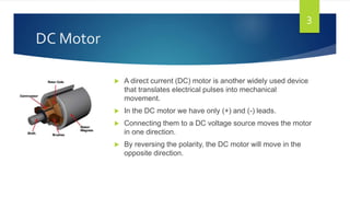
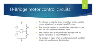
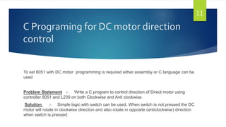
BIOMEDICAL ENGINEERING DEPARTMENT
GOVERNMENT ENGINEERING COLLEGE,
GANDHINAGAR
Dc motor direction control using
8051 microcontroller and c
programming
B.E SEM V
PREPARED BY :-
Balat Viral S. (150133103004)
Damodar Dinesh R.(150133103011)
Introduction :-
 In this topic we need to control direction of DC motor using a 8051
Microcontroller with C language Programming.
 The Maximum current that can be sourced or sunk from the a 8051
microcontroller is 15 mA at 5v.
 But a DC Motor need currents very much more than that and it need voltages 6v,
12v, 24v etc. depending upon the type of motor used.
 Another problem is that the back EMF produced by the motor may affect the
proper functioning of the microcontroller. Due to these reasons we can’t connect
a DC Motor directly to a microcontroller.
 To interface DC motor with 8051 microcontroller we requires cleared basic
fundamentals regarding to both as well programming language.
2
DC Motor
 A direct current (DC) motor is another widely used device
that translates electrical pulses into mechanical
movement.
 In the DC motor we have only (+) and (-) leads.
 Connecting them to a DC voltage source moves the motor
in one direction.
 By reversing the polarity, the DC motor will move in the
opposite direction.
3
4
 Motor can be controlled in two ways.
1) Unidirectional Control
2) Bidirectional Control
 As shown in figure DC motor rotation
for Clockwise rotation and Anticlockwise
rotation.
 With the help of relays or some specially
designed chips we can change the
direction of the DC motor rotation.
H-Bridge motor control circuits
 An h-bridge is a bipolar driver circuit that is often used to
control a load such as a brush type DC motor.
 The h-bridge consists of four switches – two half-bridges
with the load connected between them.
 The switches are usually solid-state devices such as
bipolar transistors or power MOSFET’s.
 As depicted in figure when all switches are in off condition
it is in rest condition and don’t rotates.
5
6
 When S1 and S4 are on, current tends to
flow from the positive rail of the power
supply through the motor left to right and
then to ground.
 This configuration used for rotating motor
clockwise direction.
 When S3 and S2 are on, current tends to
flow in vice versa direction this
configuration used to rotating motor in
anticlockwise direction.
 There also a third mode where the
motor leads are effectively shorted
together.
 This can be done by turning on
both high side and both low side
switches.
 This allows current to recirculate
through the motor freely. When
done briefly as the “off” portion of
a PWM cycle, it allows current to
decay slowly.
 When held in this state while a DC
motor is spinning, the back-EMF
of the motor will case a
recirculating current to flow that
will rapidly brake the motor to a
stop.
 This is known as “dynamic
braking”.
7
H-Bridge Logic configuration summary
8
Motor Operation SW1 SW2 SW3 SW4
Off Open Open Open Open
Clockwise Closed Open Open Closed
Counter Clockwise Open Closed Closed Open
Invalid Closed Closed Closed Closed
Some H-Bridge Logic Configuration for Figure
Configuration for Interface 8051 with DC
motor using L293
9
Description of the circuit
 Previous figure depicted the connection between 8051 and L293.
 For sustained operation of the motor It is required to use heat sink because L239 produce heat more
during operation.
 The opto - isolator uses to provide additional protection of the 8051
 L293 uses a separate power supply for the motor and L293 than for the 8051.
 D1,D2,D3,D4 are IN4004 diodes.
 8051 complete the task of controlling dc motor using the sequence of programming establish by
programmer the run the DC motor.
10
C Programing for DC motor direction
control
To set 8051 with DC motor programming is required either assembly or C language can be
used
Problem Statement :- Write a C program to control direction of Direct motor using
controller 8051 and L239 on both Clockwise and Anti clockwise.
Solution :- Simple logic with switch can be used. When switch is not pressed the DC
motor will rotate in clockwise direction and also rotate in opposite (anticlockwise) direction
when switch is pressed.
11
#include <reg51.h> //include header file reg51.h//
sbit SW = P2^7; //define P2.7 as a switch//
sbit ENABLE = P1^0; //define P1.0 as o/p//
sbit MTR_0 = P1^1; //define P1.1 as o/p//
sbit MTR_1 = P1^2; //define P1.2 as o/p//
void main()
{
SW = 1; //switch declares as i/p port//
ENABLE = 0; //declaring o/p port//
MTR_0 = 0; //declaring o/p port//
MTR_1 = 0; //declaring o/p port//
while(1) //Continuous loop//
{
ENABLE = 1; //toggle pin high//
if(SW == 1) //when switch is off//
{
MTR_0 = 1; //rotate in clockwise direction//
MTR_1 = 0;
}
12
else
{
MTR_0 = 0;
MTR_1 = 1; //rotate in anticlockwise direction//
}
}
}
References:-
1) THE 8051 MICROCONTROLLER AND EMBEDDED SYSTEM BY MUHAMMAD ALI MAZIDI
2) HTTP://WWW.MICRODIGITALED.COM/8051/CODE/EXAMPLE%2017-8.TXT
3) HTTPS://ELECTROSOME.COM/INTERFACING-DC-MOTOR-8051-KEIL-C-AT89C51/
4) HTTPS://THSENGINEERING.COM/2009/03/INTRO-H-BRIDGE-MOTOR-CONTROL-CIRCUITS/

DC Motor Direction Control Using 8051 C Program

  • 1.
    BIOMEDICAL ENGINEERING DEPARTMENT GOVERNMENTENGINEERING COLLEGE, GANDHINAGAR Dc motor direction control using 8051 microcontroller and c programming B.E SEM V PREPARED BY :- Balat Viral S. (150133103004) Damodar Dinesh R.(150133103011)
  • 2.
    Introduction :-  Inthis topic we need to control direction of DC motor using a 8051 Microcontroller with C language Programming.  The Maximum current that can be sourced or sunk from the a 8051 microcontroller is 15 mA at 5v.  But a DC Motor need currents very much more than that and it need voltages 6v, 12v, 24v etc. depending upon the type of motor used.  Another problem is that the back EMF produced by the motor may affect the proper functioning of the microcontroller. Due to these reasons we can’t connect a DC Motor directly to a microcontroller.  To interface DC motor with 8051 microcontroller we requires cleared basic fundamentals regarding to both as well programming language. 2
  • 3.
    DC Motor  Adirect current (DC) motor is another widely used device that translates electrical pulses into mechanical movement.  In the DC motor we have only (+) and (-) leads.  Connecting them to a DC voltage source moves the motor in one direction.  By reversing the polarity, the DC motor will move in the opposite direction. 3
  • 4.
    4  Motor canbe controlled in two ways. 1) Unidirectional Control 2) Bidirectional Control  As shown in figure DC motor rotation for Clockwise rotation and Anticlockwise rotation.  With the help of relays or some specially designed chips we can change the direction of the DC motor rotation.
  • 5.
    H-Bridge motor controlcircuits  An h-bridge is a bipolar driver circuit that is often used to control a load such as a brush type DC motor.  The h-bridge consists of four switches – two half-bridges with the load connected between them.  The switches are usually solid-state devices such as bipolar transistors or power MOSFET’s.  As depicted in figure when all switches are in off condition it is in rest condition and don’t rotates. 5
  • 6.
    6  When S1and S4 are on, current tends to flow from the positive rail of the power supply through the motor left to right and then to ground.  This configuration used for rotating motor clockwise direction.  When S3 and S2 are on, current tends to flow in vice versa direction this configuration used to rotating motor in anticlockwise direction.
  • 7.
     There alsoa third mode where the motor leads are effectively shorted together.  This can be done by turning on both high side and both low side switches.  This allows current to recirculate through the motor freely. When done briefly as the “off” portion of a PWM cycle, it allows current to decay slowly.  When held in this state while a DC motor is spinning, the back-EMF of the motor will case a recirculating current to flow that will rapidly brake the motor to a stop.  This is known as “dynamic braking”. 7
  • 8.
    H-Bridge Logic configurationsummary 8 Motor Operation SW1 SW2 SW3 SW4 Off Open Open Open Open Clockwise Closed Open Open Closed Counter Clockwise Open Closed Closed Open Invalid Closed Closed Closed Closed Some H-Bridge Logic Configuration for Figure
  • 9.
    Configuration for Interface8051 with DC motor using L293 9
  • 10.
    Description of thecircuit  Previous figure depicted the connection between 8051 and L293.  For sustained operation of the motor It is required to use heat sink because L239 produce heat more during operation.  The opto - isolator uses to provide additional protection of the 8051  L293 uses a separate power supply for the motor and L293 than for the 8051.  D1,D2,D3,D4 are IN4004 diodes.  8051 complete the task of controlling dc motor using the sequence of programming establish by programmer the run the DC motor. 10
  • 11.
    C Programing forDC motor direction control To set 8051 with DC motor programming is required either assembly or C language can be used Problem Statement :- Write a C program to control direction of Direct motor using controller 8051 and L239 on both Clockwise and Anti clockwise. Solution :- Simple logic with switch can be used. When switch is not pressed the DC motor will rotate in clockwise direction and also rotate in opposite (anticlockwise) direction when switch is pressed. 11
  • 12.
    #include <reg51.h> //includeheader file reg51.h// sbit SW = P2^7; //define P2.7 as a switch// sbit ENABLE = P1^0; //define P1.0 as o/p// sbit MTR_0 = P1^1; //define P1.1 as o/p// sbit MTR_1 = P1^2; //define P1.2 as o/p// void main() { SW = 1; //switch declares as i/p port// ENABLE = 0; //declaring o/p port// MTR_0 = 0; //declaring o/p port// MTR_1 = 0; //declaring o/p port// while(1) //Continuous loop// { ENABLE = 1; //toggle pin high// if(SW == 1) //when switch is off// { MTR_0 = 1; //rotate in clockwise direction// MTR_1 = 0; } 12 else { MTR_0 = 0; MTR_1 = 1; //rotate in anticlockwise direction// } } }
  • 13.
    References:- 1) THE 8051MICROCONTROLLER AND EMBEDDED SYSTEM BY MUHAMMAD ALI MAZIDI 2) HTTP://WWW.MICRODIGITALED.COM/8051/CODE/EXAMPLE%2017-8.TXT 3) HTTPS://ELECTROSOME.COM/INTERFACING-DC-MOTOR-8051-KEIL-C-AT89C51/ 4) HTTPS://THSENGINEERING.COM/2009/03/INTRO-H-BRIDGE-MOTOR-CONTROL-CIRCUITS/