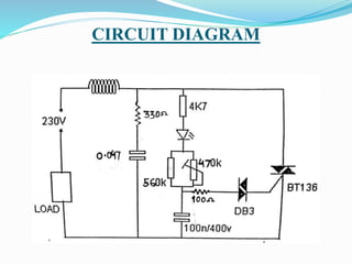
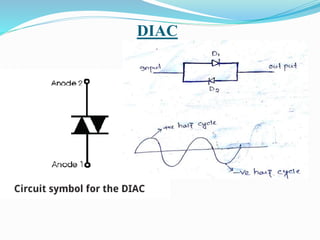
REPRESENTED BY:-
BHUBAN CH. MOHANTA(1301225034)
ABHIJIT PRADHAN(1301225142)
BHABANI PRASANNA DUTTA(1301225189)
KARTIK CHANDRA BEHERA(1301225054)
SWASTIK KUMAR DEY(1301225087)
KETAN KUMAR DAS(1301225025)
SUJESH KU. MOHAPATRA(1301225023)
BALASORE COLLEGE OF ENGG.& TECH.
SERGARH,BALASORE-756060
CONTENTS
 Introduction
Circuit description
Motor Cooling
Induction motor
SCR
TRIAC
DIAC
Application
Advantages & Disadvantages
Conclusion
Reference
INTRODUCTION
oThis project work presents a technique to control the speed of
single phase induction motor by using TRIAC and reversal of
direction of motor.
o A single phase induction motor except that its stator is provided
with a single phase winding.
o The rotor of any single phase induction motor is interchangeable
with that of a poly phase induction motor.
o A single phase winding produce no rotating magnetic field and
no starting torque.
oThe speed of Induction motor can be varied in a narrow range by
varying the voltage applied to the stator winding.
oThis method is suitable for such application where the load varies
approximately as square of speed, such as centrifugal pumps
drives, fan load, refrigerator, blower
INTRODUCTION
o The characteristics of a single phase induction motor are
identical to three phase induction motor except that single
phase induction motor has no inherent starting torque and some
special arrangement have to be made for making itself starting.
o Though single phase induction motor is not self-starting, we
are using it because the three phase supply is not present at
everywhere.
o The voltage variation as well as power control of inductive
load is essential in industrial sector.
o The load may any motor or any inductive load.
o We can use thyristor to this job but it is easier using TRIAC.
INTRODUCTION
o Here we use a different type of triggering device called DIAC.
o Firing angle can be controlled through RC circuit.
o The vast majority of dimmer circuits is only suitable for
regulating resistive (nonreactive) loads, i.e., when there is no
phase difference between the mains voltage and the load
current.
o This means that the trigger pulses can be kept relatively short,
singe the load current-is in phase with the mains voltage
immediately after triggering has taken place
o Normally, the load current is greater than the holding current,
so that the TRIAC or thyristor is triggered immediately, and
remains on.
FEATURES
 Speed controller uses TRIAC as driving device for induction
motor.
 DIAC is used as triggering device.
 Upto 4kw inductive load or induction motor can be controlled.
 Very wide range of control.
CIRCUIT DIAGRAM
CIRCUIT DESCRIPTION
 Here we use TRIAC as a switching element.
 The firing scheme is done through RC network. R is 560K
parallel with 470k and c is 100pf.
 RC time delay varies between 0.0 sec to 0.01 sec. the more the
delay less will be power available to load.
 Firing angle α depends upon RC time constant.
 Variable resistance 470k ohms changes the firing angle.
 470k protects the circuit whenever there is failure of variable
resistance 560k.
CIRCUIT DESCRIPTION
 voltage across capacitor 0.1 rises & when breakdown
voltage ( 30v) achieved, then only TRIAC is triggered with a
small pulse.
 As resistance is low capacitor is charged quickly and so power
available to load is more and vice versa.
 A capacitor 0.01µF capacitor is connected across the
TRIAC for as snubber circuit for dv/dt protection.
 A inductor is also creates the snubber circuit to protect of
TRIAC from di/dt protection.
 Here is a LED is provided as indicator.
MOTOR COOLING
 Energy transfer and energy conversion in rotating machines
manifests losses.
 These losses appear as heat and increase temperature of the
machine beyond its optimum level.
 Heat is dissipated to surrounding by conduction and
convection assisted by radiation from outer surfaces.
 The cooling fan circulates air through the fan so it can release
motor heat into the surrounding air.
 With the introduction of cooling fan become more efficient by
operating only when they need to.
 Electric cooling fan also improve the operation of the air
conditioning system.
Block diagram of motor cooling
A 12v regulated supply is taken as followed:
Each of the blocks is described in more detail below:
 Transformer - steps down high voltage AC mains to low
voltage AC.
 Rectifier - converts AC to DC, but the DC output is varying.
 Filtering - filtering the DC from varying greatly to a small
ripple.
 Regulator - eliminates ripple by setting DC output to a fixed
voltage.
Circuit diagram of motor cooling
INDUCTION MOTOR
 An induction motor is an AC
electric motor in which
the electric current in the
rotor needed to produce
torque is obtained
by electromagnetic
induction from the magnetic
field of the stator winding.
 This motor can therefore be
made without electrical
connections to the rotor.
 An induction motor's rotor
can be either wound
type or squirrel-cage type.
INDUCTION MOTOR
It is divided into two types
1.Single Phase Induction Motor
2.Three Phase Induction Motor
Single Phase Induction Motor
 Single phase induction motors consist of two main parts; stator
and rotor.
 The stator is a stationary part and it has laminated construction,
which is made up of stampings.
 These stampings consists of slots on its periphery to carry the
stator winding. This winding is excited with a single phase AC
supply.
 The rotor is a rotating part and its construction is of squirrel
cage type. The rotor consists of uninsulated aluminum or
copper bars which are placed in the slots
INDUCTION MOTOR
Construction:-
STATOR ROTOR
INDUCTION MOTOR
Working Principle of Single Phase Induction Motor
 We know that for the working of any electrical motor whether
its ac or DC motor, we require two fluxes as, the interaction of
these two fluxes produced the required torque, which is desired
parameter for any motor to rotate.
 When single phase ac supply is given to the stator winding of
single phase induction motor, the alternating current starts
flowing through the stator or main winding.
 This alternating current produces an alternating flux called
main flux.
 This main flux also links with the rotor conductors and hence
cut the rotor conductors.
INDUCTION MOTOR
 According to the Faraday’s law of electromagnetic induction,
emf gets induced in the rotor.
 As the rotor circuit is closed one so, the current starts flowing
in the rotor.
 This current is called the rotor current.
 This rotor current produces its own flux called rotor flux. Since
this flux is produced due to induction principle so, the motor
working on this principle got its name as induction motor.
 Now there are two fluxes one is main flux and another is
called rotor flux.
 These two fluxes produce the desired torque which is required
by the motor to rotate.
INDUCTION MOTOR
 TYPES OF SINGLE PHASE INDUCTION MOTORS
Based on the starting method, single phase induction motors
are basically classified into the following types.
1.Split-phase motor
2.Capacitor start motor
3.Permanent capacitor run motor
4.Capacitor start capacitor run motor
5.Shaded pole motor
INDUCTION MOTOR
Permanent Capacitor Induction Motor
SCR(Silicon Controlled Rectifier)
 A silicon controlled rectifier or semiconductor-controlled
rectifier is a four-layer solid-state current-controlling device...
 SCRs are unidirectional devices.
 It is a current controlled device.
 SCRs can be triggered normally by either a positive or a
negative current applied to its gate electrode.
Construction :-
 The silicon control rectifier (SCR) consists of four layers of
semiconductors, which form NPNP or PNPN structures have
three P-N junctions labeled J1, J2 and J3, and three terminals.
 The anode terminal of an SCR is connected to the p-type
material of a PNPN structure and the cathode terminal is
connected to the n-type layer.
SCR(Silicon Controlled Rectifier)
Modes of operation :-
There are three modes of operation for an SCR depending upon the
biasing given to it:
•Forward blocking mode (off state)
•Forward conduction mode (on state)
•Reverse blocking mode (off state)
SCR(Silicon Controlled Rectifier)
Thyristor turn-on methods:-
1.Forward-voltage triggering
2. Gate triggering
3. dv/dt triggering
4.Temperature triggering
5. Light triggering
SCR(Silicon Controlled Rectifier)
TRIAC
 TRIAC is a three terminal
electronic component that
conduct current in either
direction when triggered.
 Its full form is triode with
AC, which conduct in both
positive half cycle and in
negative half cycle.
 TRIAC have three terminals,
main terminal i.e (MT1 and
MT2),one gate terminal as as
shown in the fig.
TRIAC OPERATION
 TRIAC have two SCR connected
in anti-parallel manner as shown in
the fig.
 Whenever gate pulse is applied to
its gate terminal it becomes turn on
and switch to conduct.
 When positive half cycle gives to
TRIAC the SCR1 conduct.
 And in negative half cycle the SCR2
is conduct.
CONSTRUCTION OF TRIAC
 When MT2 is positive with
respect to MT1 then the TRIAC
conduct through P1-N1-P2-N2.
 When MT2 is negative with
respect to MT1 then TRIAC
should conduct through P2-N1-
P1-N4.
 In this way the TRIAC conduct in
both half of cycle in ac supply.
CHARACTERISTICS OF TRIAC
DIAC
The full form of DIAC is Diode Alternating Circuit.
It is a bidirectional semiconductor device that can allows the
current to pass through the both direction i.e. in forward and
reverse direction.
The DIAC gains its name from the contraction of the
words Diode Alternating Current.
The DIAC is widely used to assist even triggering of a TRIAC
when used in AC switches.
 DIACs are mainly used in dimmer applications and also in
starter circuits for florescent lamps.
DIAC
DIAC OPERATION
 The DIAC is essentially a diode that conducts after a 'break-
over' voltage, designated VBO, is exceeded.
 When the device exceeds this break-over voltage, it enters the
region of negative dynamic resistance.
 This results in a decrease in the voltage drop across the diode
with increasing voltage.
 Accordingly there is a sharp increase in the level of current
that is conducted by the device. The DIAC is essentially a
diode that conducts after a 'break-over' voltage, designated
VBO, is exceeded.
 When the device exceeds this break-over voltage, it enters the
region of negative dynamic resistance.
 This results in a decrease in the voltage drop across the diode
with increasing voltage. Accordingly there is a sharp increase
in the level of current that is conducted by the device.
DIAC APPLICATION
 Typically the DIAC is placed in series with the gate of a
TRIAC.
 DIACs are often used in conjunction with TRIACs because
these devices do not fire symmetrically as a result of slight
differences between the two halves of the device.
 This results in harmonics being generated, and the less
symmetrical the device fires, the greater the level of harmonics
produced.
 It is generally undesirable to have high levels of harmonics in a
power system.
APPLICATION
•Motor speed regulation.
•In manufacturing Industries.
•For domestic use.
•Speed control motor.
•Helpful for conserving electrical energy.
•No heat loss in conduction of load current.
ADVANTAGES
 Induction motor is cheaper in cost.
 Low maintenance.
 Construction of its controlling circuit is very easy.
 They can be operated in hazardous environments.
 They do not produce sparks unlike dc motor.
DISADVANTAGES
 Speed control in induction motor is difficult.
 At low loads the power factor drops to very low values.
 Efficiency drops at low load, this results in higher copper
loss.
 Poor starting torque.
CONCLUSION
 In this paper we proposed a new method to control the speed of
single–phase induction motor in both directions by the use of a
semiconductor device TRIAC and reversed bidirectional by the
use of DIAC. This method is the effective and efficient method
to control the speed of single-phase induction motor in today’s
world.
 It is so designed so that it is complete from any angle like
from technical point of view, from economical point of view.
In testing and working it is working properly as per theory.
Therefore is it is feasible one to lunch to market for public use.
This will reduce the power consumption.
REFERENCE
 Dr. P.S. Bimbhra “Generalize theory of electrical machine”
department of Electrical engineering, Thapar Institute of
Engineering and Technology, Patiala. 147001.
 “Speed Control Of Induction Motor Drive Using Universal
Controller”, IEEE Trans. Ind, 2010.
 Mineo Tsuji, Shuo Chen, Shin-ichiHamasaki, Xiaodan Zhao,
and Eiji Yamada, “A Novel V/f Control of Induction Motors for
Wide and Precise Speed Operation” IEEE Trans. Ind.
 Muhammad H. Rashid “Power electronics circuits, devices and
applications” third edition, department of Electrical and
Computer engineering, University of West Florida.
 Ashfaq Husain “Electrical machines” second edition, Formerly,
Reader in Electrical engineering University Polytechnic,
Aligarh Muslim University, Aligarh.
Speed Control Of Single Phase Induction Motor

Speed Control Of Single Phase Induction Motor

  • 1.
    REPRESENTED BY:- BHUBAN CH.MOHANTA(1301225034) ABHIJIT PRADHAN(1301225142) BHABANI PRASANNA DUTTA(1301225189) KARTIK CHANDRA BEHERA(1301225054) SWASTIK KUMAR DEY(1301225087) KETAN KUMAR DAS(1301225025) SUJESH KU. MOHAPATRA(1301225023) BALASORE COLLEGE OF ENGG.& TECH. SERGARH,BALASORE-756060
  • 2.
    CONTENTS  Introduction Circuit description MotorCooling Induction motor SCR TRIAC DIAC Application Advantages & Disadvantages Conclusion Reference
  • 3.
    INTRODUCTION oThis project workpresents a technique to control the speed of single phase induction motor by using TRIAC and reversal of direction of motor. o A single phase induction motor except that its stator is provided with a single phase winding. o The rotor of any single phase induction motor is interchangeable with that of a poly phase induction motor. o A single phase winding produce no rotating magnetic field and no starting torque. oThe speed of Induction motor can be varied in a narrow range by varying the voltage applied to the stator winding. oThis method is suitable for such application where the load varies approximately as square of speed, such as centrifugal pumps drives, fan load, refrigerator, blower
  • 4.
    INTRODUCTION o The characteristicsof a single phase induction motor are identical to three phase induction motor except that single phase induction motor has no inherent starting torque and some special arrangement have to be made for making itself starting. o Though single phase induction motor is not self-starting, we are using it because the three phase supply is not present at everywhere. o The voltage variation as well as power control of inductive load is essential in industrial sector. o The load may any motor or any inductive load. o We can use thyristor to this job but it is easier using TRIAC.
  • 5.
    INTRODUCTION o Here weuse a different type of triggering device called DIAC. o Firing angle can be controlled through RC circuit. o The vast majority of dimmer circuits is only suitable for regulating resistive (nonreactive) loads, i.e., when there is no phase difference between the mains voltage and the load current. o This means that the trigger pulses can be kept relatively short, singe the load current-is in phase with the mains voltage immediately after triggering has taken place o Normally, the load current is greater than the holding current, so that the TRIAC or thyristor is triggered immediately, and remains on.
  • 6.
    FEATURES  Speed controlleruses TRIAC as driving device for induction motor.  DIAC is used as triggering device.  Upto 4kw inductive load or induction motor can be controlled.  Very wide range of control.
  • 7.
  • 8.
    CIRCUIT DESCRIPTION  Herewe use TRIAC as a switching element.  The firing scheme is done through RC network. R is 560K parallel with 470k and c is 100pf.  RC time delay varies between 0.0 sec to 0.01 sec. the more the delay less will be power available to load.  Firing angle α depends upon RC time constant.  Variable resistance 470k ohms changes the firing angle.  470k protects the circuit whenever there is failure of variable resistance 560k.
  • 9.
    CIRCUIT DESCRIPTION  voltageacross capacitor 0.1 rises & when breakdown voltage ( 30v) achieved, then only TRIAC is triggered with a small pulse.  As resistance is low capacitor is charged quickly and so power available to load is more and vice versa.  A capacitor 0.01µF capacitor is connected across the TRIAC for as snubber circuit for dv/dt protection.  A inductor is also creates the snubber circuit to protect of TRIAC from di/dt protection.  Here is a LED is provided as indicator.
  • 10.
    MOTOR COOLING  Energytransfer and energy conversion in rotating machines manifests losses.  These losses appear as heat and increase temperature of the machine beyond its optimum level.  Heat is dissipated to surrounding by conduction and convection assisted by radiation from outer surfaces.  The cooling fan circulates air through the fan so it can release motor heat into the surrounding air.  With the introduction of cooling fan become more efficient by operating only when they need to.  Electric cooling fan also improve the operation of the air conditioning system.
  • 11.
    Block diagram ofmotor cooling A 12v regulated supply is taken as followed: Each of the blocks is described in more detail below:  Transformer - steps down high voltage AC mains to low voltage AC.  Rectifier - converts AC to DC, but the DC output is varying.  Filtering - filtering the DC from varying greatly to a small ripple.  Regulator - eliminates ripple by setting DC output to a fixed voltage.
  • 12.
    Circuit diagram ofmotor cooling
  • 13.
    INDUCTION MOTOR  Aninduction motor is an AC electric motor in which the electric current in the rotor needed to produce torque is obtained by electromagnetic induction from the magnetic field of the stator winding.  This motor can therefore be made without electrical connections to the rotor.  An induction motor's rotor can be either wound type or squirrel-cage type.
  • 14.
    INDUCTION MOTOR It isdivided into two types 1.Single Phase Induction Motor 2.Three Phase Induction Motor Single Phase Induction Motor  Single phase induction motors consist of two main parts; stator and rotor.  The stator is a stationary part and it has laminated construction, which is made up of stampings.  These stampings consists of slots on its periphery to carry the stator winding. This winding is excited with a single phase AC supply.  The rotor is a rotating part and its construction is of squirrel cage type. The rotor consists of uninsulated aluminum or copper bars which are placed in the slots
  • 15.
  • 16.
    INDUCTION MOTOR Working Principleof Single Phase Induction Motor  We know that for the working of any electrical motor whether its ac or DC motor, we require two fluxes as, the interaction of these two fluxes produced the required torque, which is desired parameter for any motor to rotate.  When single phase ac supply is given to the stator winding of single phase induction motor, the alternating current starts flowing through the stator or main winding.  This alternating current produces an alternating flux called main flux.  This main flux also links with the rotor conductors and hence cut the rotor conductors.
  • 17.
    INDUCTION MOTOR  Accordingto the Faraday’s law of electromagnetic induction, emf gets induced in the rotor.  As the rotor circuit is closed one so, the current starts flowing in the rotor.  This current is called the rotor current.  This rotor current produces its own flux called rotor flux. Since this flux is produced due to induction principle so, the motor working on this principle got its name as induction motor.  Now there are two fluxes one is main flux and another is called rotor flux.  These two fluxes produce the desired torque which is required by the motor to rotate.
  • 18.
    INDUCTION MOTOR  TYPESOF SINGLE PHASE INDUCTION MOTORS Based on the starting method, single phase induction motors are basically classified into the following types. 1.Split-phase motor 2.Capacitor start motor 3.Permanent capacitor run motor 4.Capacitor start capacitor run motor 5.Shaded pole motor
  • 19.
  • 20.
    SCR(Silicon Controlled Rectifier) A silicon controlled rectifier or semiconductor-controlled rectifier is a four-layer solid-state current-controlling device...  SCRs are unidirectional devices.  It is a current controlled device.  SCRs can be triggered normally by either a positive or a negative current applied to its gate electrode. Construction :-  The silicon control rectifier (SCR) consists of four layers of semiconductors, which form NPNP or PNPN structures have three P-N junctions labeled J1, J2 and J3, and three terminals.  The anode terminal of an SCR is connected to the p-type material of a PNPN structure and the cathode terminal is connected to the n-type layer.
  • 21.
    SCR(Silicon Controlled Rectifier) Modesof operation :- There are three modes of operation for an SCR depending upon the biasing given to it: •Forward blocking mode (off state) •Forward conduction mode (on state) •Reverse blocking mode (off state)
  • 22.
    SCR(Silicon Controlled Rectifier) Thyristorturn-on methods:- 1.Forward-voltage triggering 2. Gate triggering 3. dv/dt triggering 4.Temperature triggering 5. Light triggering
  • 23.
  • 24.
    TRIAC  TRIAC isa three terminal electronic component that conduct current in either direction when triggered.  Its full form is triode with AC, which conduct in both positive half cycle and in negative half cycle.  TRIAC have three terminals, main terminal i.e (MT1 and MT2),one gate terminal as as shown in the fig.
  • 25.
    TRIAC OPERATION  TRIAChave two SCR connected in anti-parallel manner as shown in the fig.  Whenever gate pulse is applied to its gate terminal it becomes turn on and switch to conduct.  When positive half cycle gives to TRIAC the SCR1 conduct.  And in negative half cycle the SCR2 is conduct.
  • 26.
    CONSTRUCTION OF TRIAC When MT2 is positive with respect to MT1 then the TRIAC conduct through P1-N1-P2-N2.  When MT2 is negative with respect to MT1 then TRIAC should conduct through P2-N1- P1-N4.  In this way the TRIAC conduct in both half of cycle in ac supply.
  • 27.
  • 28.
    DIAC The full formof DIAC is Diode Alternating Circuit. It is a bidirectional semiconductor device that can allows the current to pass through the both direction i.e. in forward and reverse direction. The DIAC gains its name from the contraction of the words Diode Alternating Current. The DIAC is widely used to assist even triggering of a TRIAC when used in AC switches.  DIACs are mainly used in dimmer applications and also in starter circuits for florescent lamps.
  • 29.
  • 30.
    DIAC OPERATION  TheDIAC is essentially a diode that conducts after a 'break- over' voltage, designated VBO, is exceeded.  When the device exceeds this break-over voltage, it enters the region of negative dynamic resistance.  This results in a decrease in the voltage drop across the diode with increasing voltage.  Accordingly there is a sharp increase in the level of current that is conducted by the device. The DIAC is essentially a diode that conducts after a 'break-over' voltage, designated VBO, is exceeded.  When the device exceeds this break-over voltage, it enters the region of negative dynamic resistance.  This results in a decrease in the voltage drop across the diode with increasing voltage. Accordingly there is a sharp increase in the level of current that is conducted by the device.
  • 31.
    DIAC APPLICATION  Typicallythe DIAC is placed in series with the gate of a TRIAC.  DIACs are often used in conjunction with TRIACs because these devices do not fire symmetrically as a result of slight differences between the two halves of the device.  This results in harmonics being generated, and the less symmetrical the device fires, the greater the level of harmonics produced.  It is generally undesirable to have high levels of harmonics in a power system.
  • 32.
    APPLICATION •Motor speed regulation. •Inmanufacturing Industries. •For domestic use. •Speed control motor. •Helpful for conserving electrical energy. •No heat loss in conduction of load current.
  • 33.
    ADVANTAGES  Induction motoris cheaper in cost.  Low maintenance.  Construction of its controlling circuit is very easy.  They can be operated in hazardous environments.  They do not produce sparks unlike dc motor.
  • 34.
    DISADVANTAGES  Speed controlin induction motor is difficult.  At low loads the power factor drops to very low values.  Efficiency drops at low load, this results in higher copper loss.  Poor starting torque.
  • 35.
    CONCLUSION  In thispaper we proposed a new method to control the speed of single–phase induction motor in both directions by the use of a semiconductor device TRIAC and reversed bidirectional by the use of DIAC. This method is the effective and efficient method to control the speed of single-phase induction motor in today’s world.  It is so designed so that it is complete from any angle like from technical point of view, from economical point of view. In testing and working it is working properly as per theory. Therefore is it is feasible one to lunch to market for public use. This will reduce the power consumption.
  • 36.
    REFERENCE  Dr. P.S.Bimbhra “Generalize theory of electrical machine” department of Electrical engineering, Thapar Institute of Engineering and Technology, Patiala. 147001.  “Speed Control Of Induction Motor Drive Using Universal Controller”, IEEE Trans. Ind, 2010.  Mineo Tsuji, Shuo Chen, Shin-ichiHamasaki, Xiaodan Zhao, and Eiji Yamada, “A Novel V/f Control of Induction Motors for Wide and Precise Speed Operation” IEEE Trans. Ind.  Muhammad H. Rashid “Power electronics circuits, devices and applications” third edition, department of Electrical and Computer engineering, University of West Florida.  Ashfaq Husain “Electrical machines” second edition, Formerly, Reader in Electrical engineering University Polytechnic, Aligarh Muslim University, Aligarh.