The document discusses speed control of a DC motor using a chopper, specifically employing the armature voltage control method. It explains the principles of chopper operation, types of choppers, and their applications in motor control and regenerative braking. The simulation results demonstrate successful speed control under varying conditions, and the findings can potentially be implemented in hardware.
Speed control ofdc motor using
chopper
Presented by: Under the guidance of:
Ajeeta Srivastava (1473720005) Assi. Prof. Nikhil Chowdhary
Akansha (1473720006)
DEPARTMENT OF ELECTRICAL ENGINEERING
RAJKIYA ENGINEERING COLLEGE
AMBEDKAR NAGAR-224122(U.P.)
2.
Abstract
The speed ofa d.c. motor is given by relationship
N= ( V- Ia Ra)/kΦ
Speed of dc motor can be varied by following methods
Armature voltage control (for below base speed)
Field flux control (for above base speed)
Armature resistance control
Here, we are using armature voltage control method for
speed control. In this method, the voltage applied to
armature circuit, V is varied using DC-DC converter, a
power electronics device which converts fixed dc input
voltage to a variable dc output voltage.
3.
Introduction
Chopper arestatic power electronics device which
converts fixed dc input voltage to a variable dc
output voltage. It can be step-up or step-down.
Separately excited dc motor has field winding and
armature winding with separate supply voltage.
Field winding supplies field flux to armature.
When dc voltage is supplied to motor, current is fed
to the armature winding through brushes and
commutator .
4.
Choppers
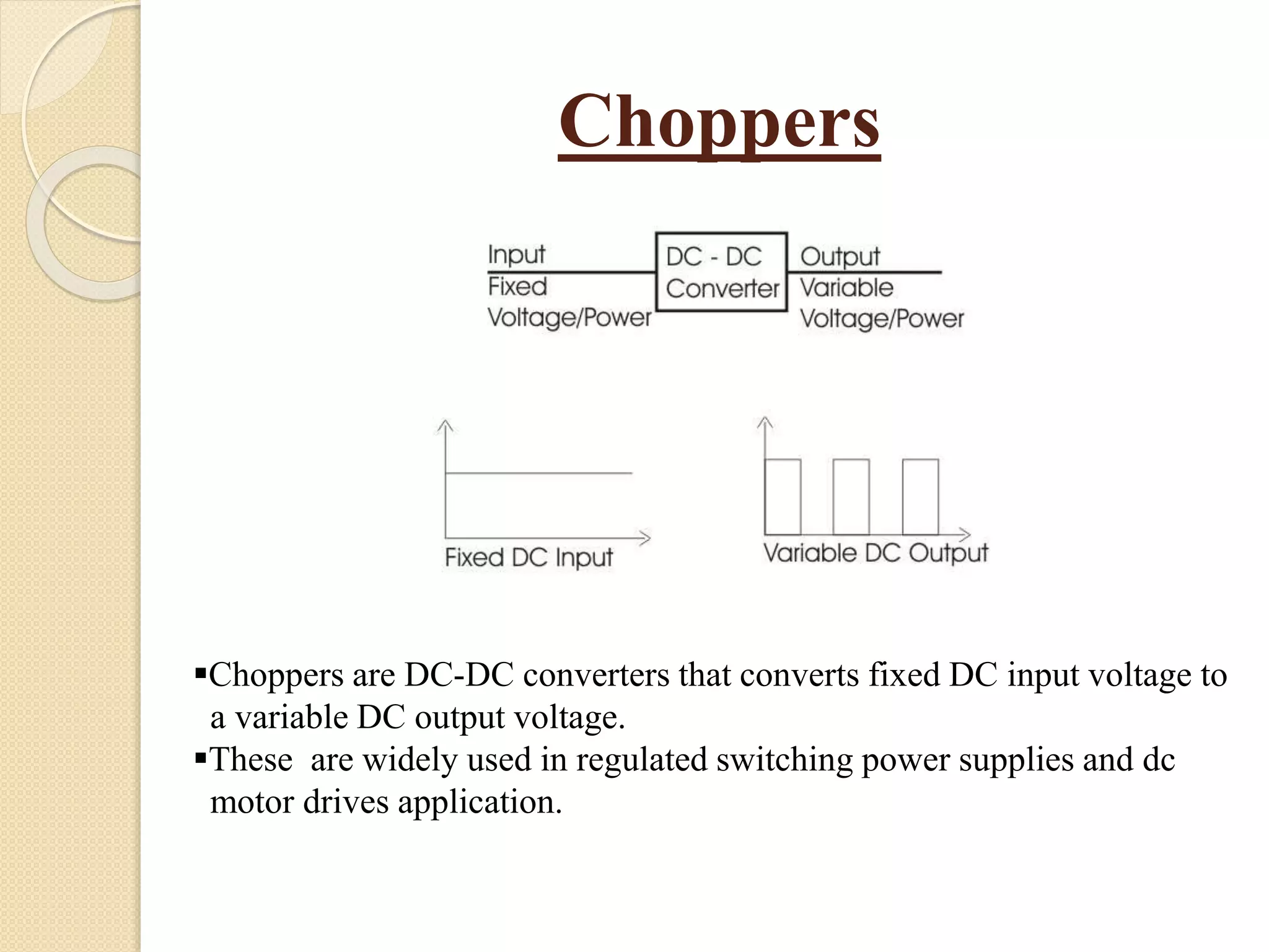
Choppers are DC-DCconverters that converts fixed DC input voltage to
a variable DC output voltage.
These are widely used in regulated switching power supplies and dc
motor drives application.
5.
Types of Choppers
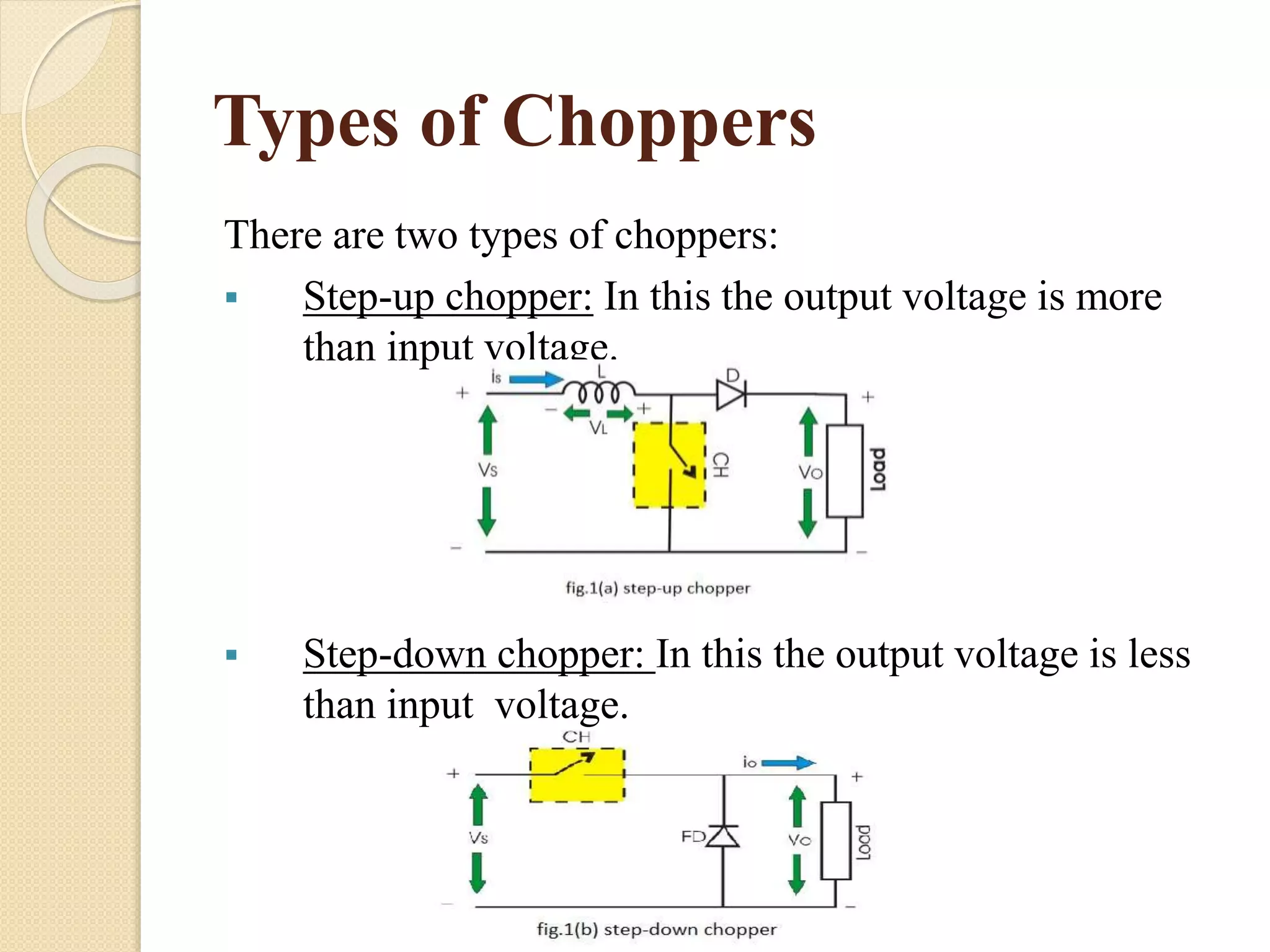
Thereare two types of choppers:
Step-up chopper: In this the output voltage is more
than input voltage.
Step-down chopper: In this the output voltage is less
than input voltage.
6.
Principle of Chopperoperation
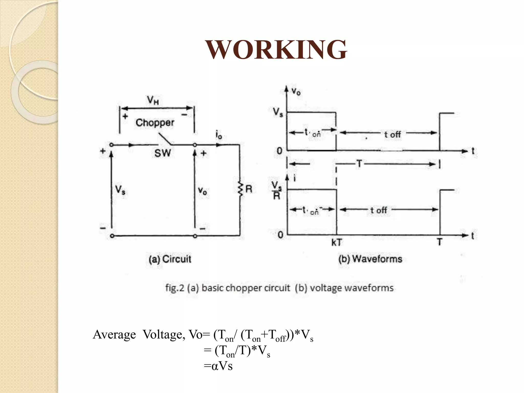
There are basically two time periods in chopper
operation, one is the “on” time denoted as TON and
other is the “off” time denoted as TOFF.
During TON we get the constant source voltage VS
across the load and during TOFF we get zero voltage
across the load.
In this way we obtain a chopped dc voltage at the load
terminals.
Working Of SeparatelyExcited DC
Motor
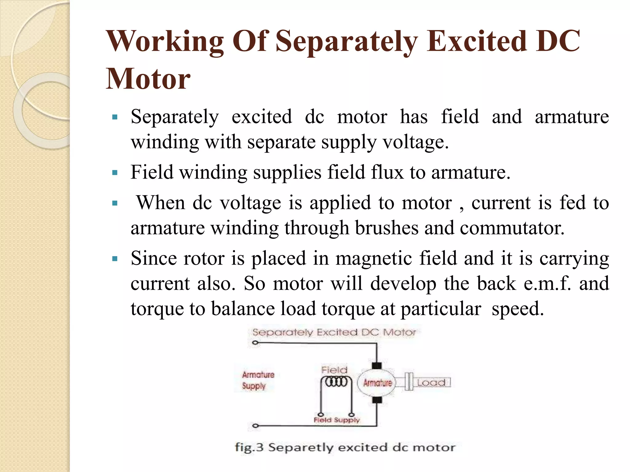
Separately excited dc motor has field and armature
winding with separate supply voltage.
Field winding supplies field flux to armature.
When dc voltage is applied to motor , current is fed to
armature winding through brushes and commutator.
Since rotor is placed in magnetic field and it is carrying
current also. So motor will develop the back e.m.f. and
torque to balance load torque at particular speed.
Application of chopperin DC
Motor
1) For regenerative braking of DC motor
2) Power control or motoring control
3) Choppers are used in electric cars, airplanes and
spaceships, where onboard-regulated DC power
supplies are required.
11.
Simulation Result
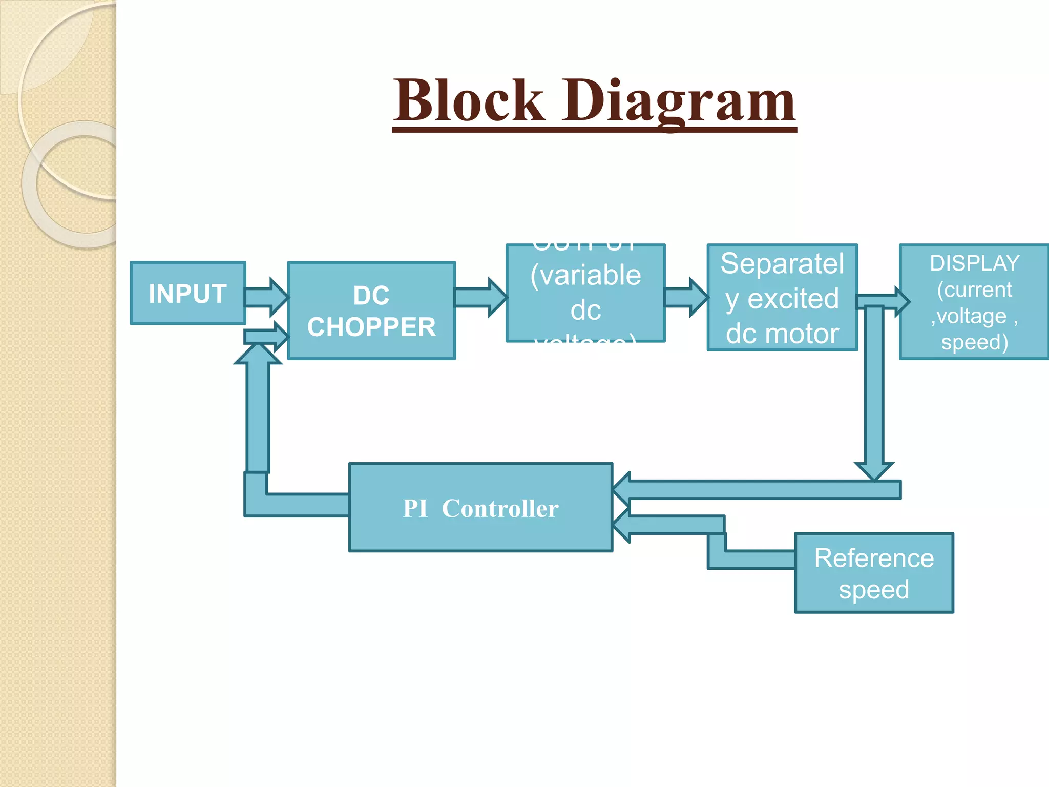
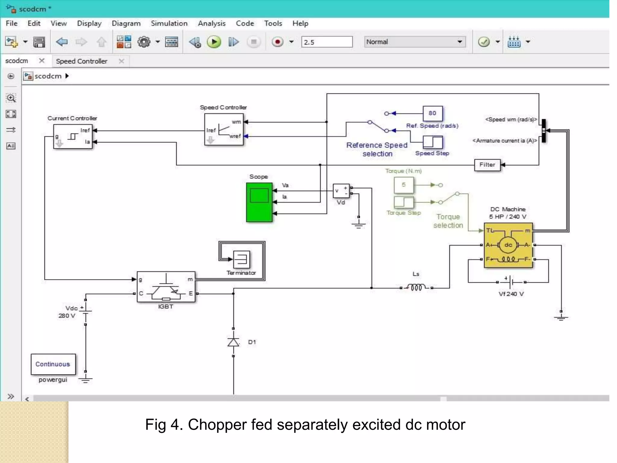
The simulinkmodel of speed control of DC motor is
shown in figure 4. It consists of speed controller ,
current controller, filter , chopper and a motor . Now the
simulation of model is done and analyzed in MATLAB
(Simulink) under varying speed and torque condition.
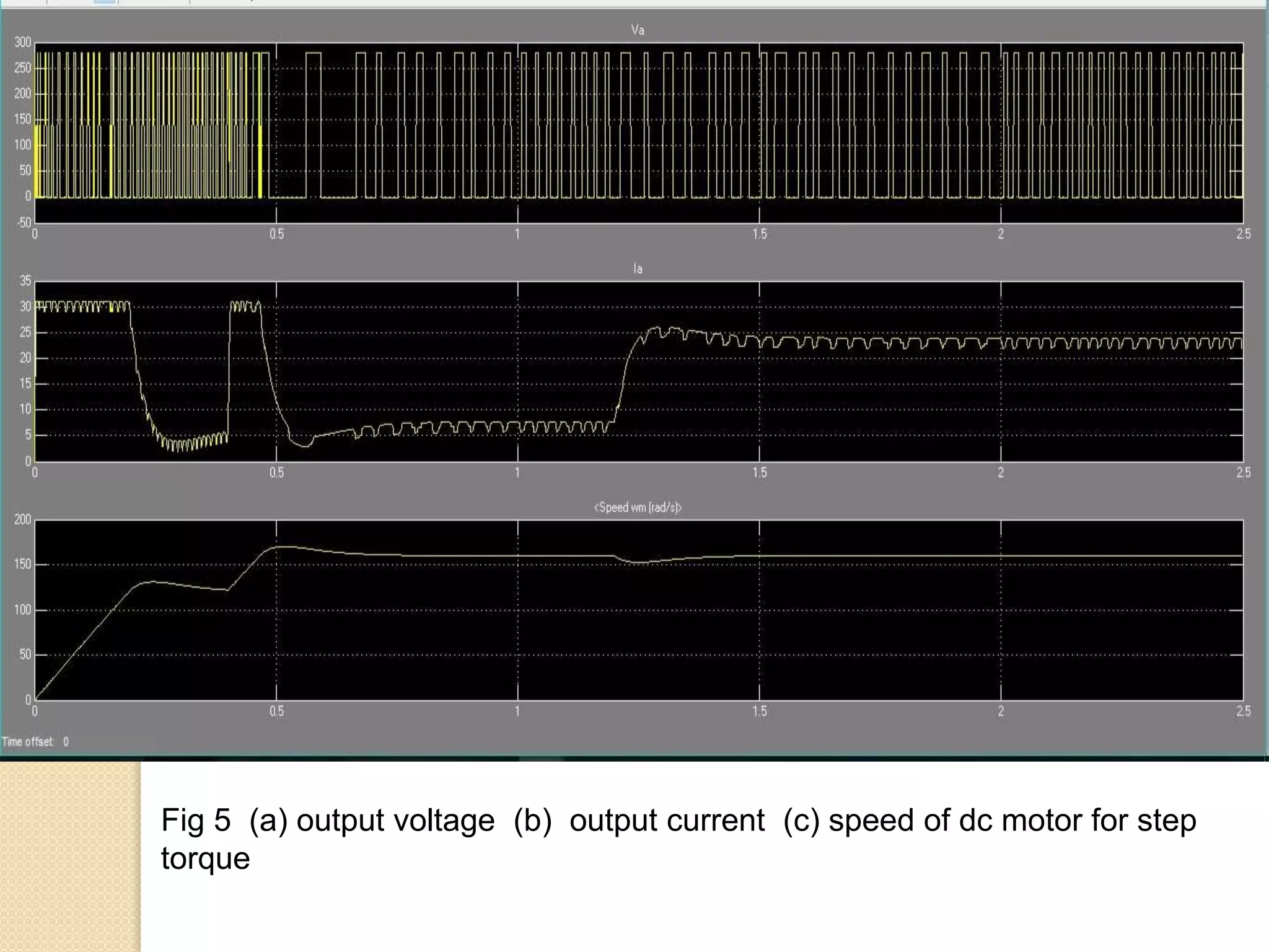
The result from the simulation of the motor model in
SIMULINK is shown in figure 5(a),5(b),5(c),6(a),6(b)
and 6(c).
Fig 5 (a)output voltage (b) output current (c) speed of dc motor for step
torque
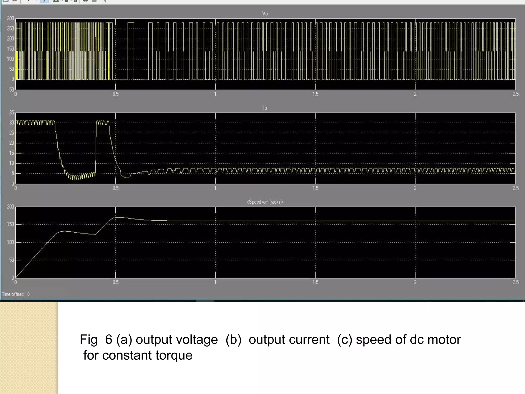
14.
Fig 6 (a)output voltage (b) output current (c) speed of dc motor
for constant torque
15.
Conclusion
The speed ofa DC motor has been successfully
controlled by using chopper as converter and
proportional-integral type speed and current controller
based on closed loop model of dc motor. The simulation
is done in MATLAB under varying load condition and
varying reference speed condition .We can also
implement it in hardware to observe actual feasibility.