Download to read offline

![International Research Journal of Engineering and Technology (IRJET) e-ISSN: 2395 -0056
Volume: 04 Issue: 03 | Mar -2017 www.irjet.net p-ISSN: 2395-0072
© 2017, IRJET | Impact Factor value: 5.181 | ISO 9001:2008 Certified Journal | Page 1615
digitalWrite(moc5,HIGH);
digitalWrite(moc6,HIGH);
digitalWrite(moc7,HIGH);
digitalWrite(moc8,HIGH);
delay(0.5);
digitalWrite(moc5,LOW);
digitalWrite(moc6,LOW);
digitalWrite(moc7,LOW);
digitalWrite(moc8,LOW);
delay(29.5);
}
else
{
digitalWrite(moc1,LOW);
digitalWrite(moc2,LOW);
digitalWrite(moc3,LOW);
digitalWrite(moc4,LOW);
digitalWrite(moc5,LOW);
digitalWrite(moc6,LOW);
digitalWrite(moc7,LOW);
digitalWrite(moc8,LOW);
}
}
}
3.3 Technical Specifications of Arduino Micro -
Controller
Table of Technical Specifications:
Microcontroller ATmega328P
Operating Voltage 5V
Input Voltage (recommended) 7-12 V
Input Voltage (limit) 6-20 V
Digital I/O Pins 14
Clock Speed 16MHz
PWM Digital I/O Pins 6
Analog Input Pins 6
DC Current per I/O Pins 20mA
DC Current for 3.3V Pin 50mA
SRAM 2KB
EPROM 1KB
Flash Memory 32KB
LED BUILTIN 13
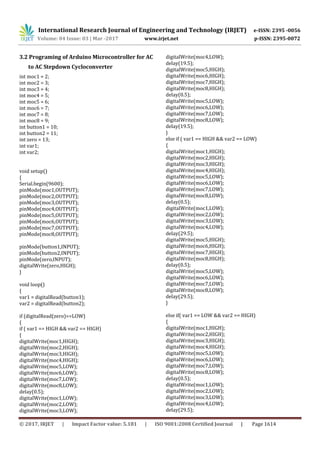
4. CONCLUSIONS
From this work it is observed that speed of an induction
motor can be efficiently controlled by using Cycloconverter.
The role of Cycloconverter is in speed control of induction
motor is to vary the supply frequency which inturn, changes
the speed of motor. The speed control of induction motor
can be achieved in three steps i.e. (F, F/2 and F/3).
REFERENCES
[1] Vinamra Kumar Govil, Yogesh Chaurasia “Modeling &
Simulation of PWM Controlled Cycloconverter FED Split
Phase Induction Motor” International Journal of Advanced
Research in Electrical, Electronics and Instrumentation
Engineering, Vol. 1, Issue 3, September 2012.
[2] E A Lewis “Cycloconverter Drive Systems” Power
Electronics and Variable Speed Drives, Conference
Publication No. 429, IEEE, 1996.
[3] C. Lander, Power Electronics, Second Edition, McGraw
Hill, England, 1987
[4] BurakOzpineci, Leon M. Tolbert, “Cycloconverters”,
University of Tennessee-Knoxville, Knoxville, USA.
[5] J. Zhang, “Single phase input cycloconverters driving an
induction motor” Ph.D. thesis, University of Technology,
Sydney.](https://image.slidesharecdn.com/irjet-v4i3362-171227083758/85/AC-to-AC-Step-Down-Cycloconverter-5-320.jpg)


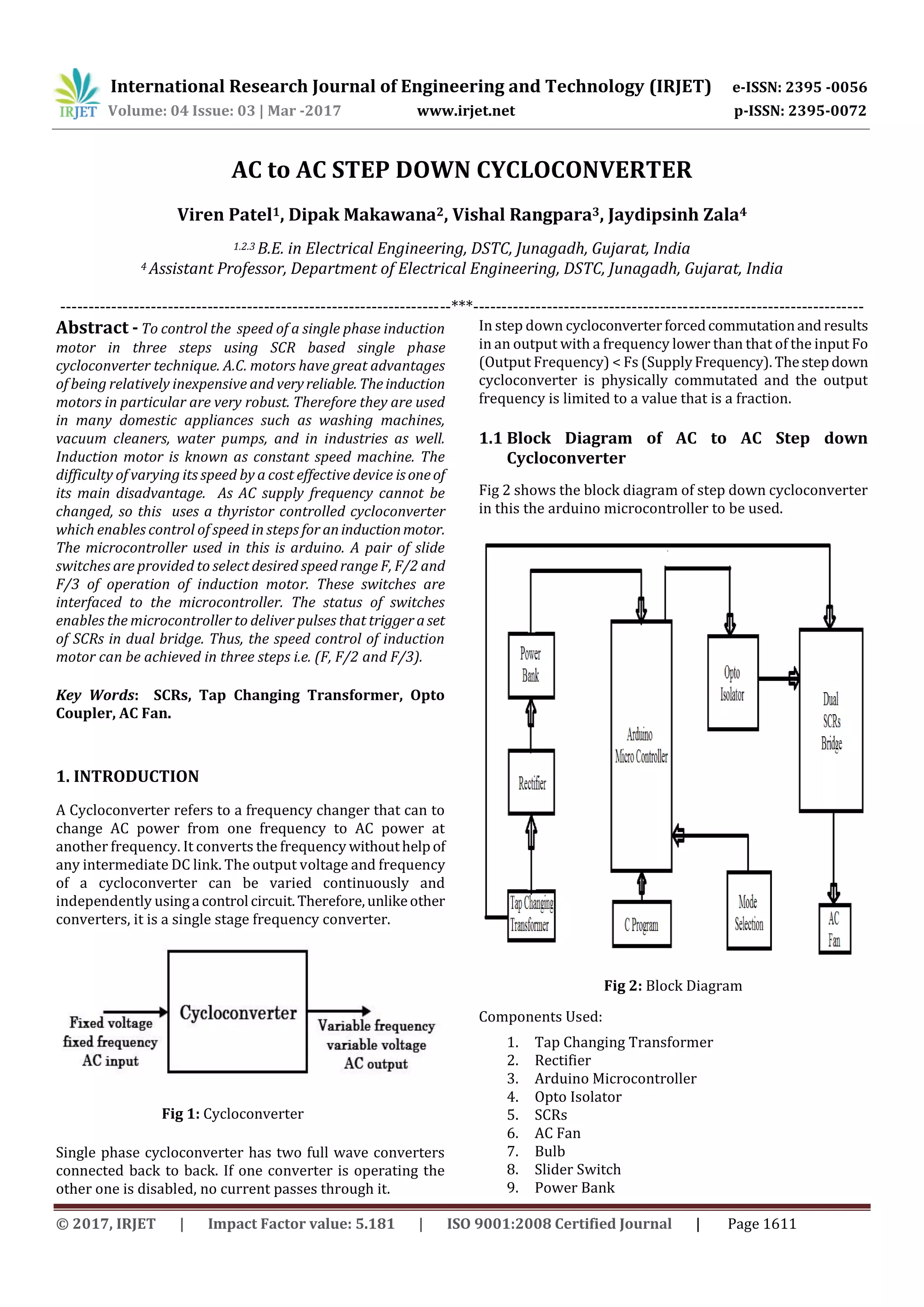
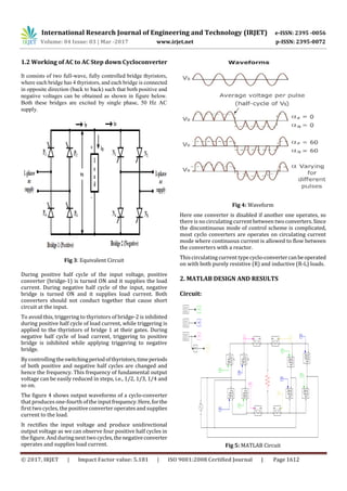
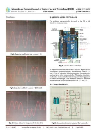
This document describes an AC to AC step down cycloconverter that uses SCRs and an Arduino microcontroller to control the speed of an induction motor in three steps (full speed, half speed, and one-third speed). A cycloconverter can change the frequency of AC power without an intermediate DC link. This single-stage cycloconverter has two full-wave thyristor bridges connected back-to-back to produce an output frequency lower than the input frequency. The Arduino receives signals from slide switches to select the motor speed and triggers the appropriate SCRs to achieve speed control in three steps. MATLAB simulations show the output waveforms at different speeds. Pseudocode is provided for the Arduino program.


![Share 'speed control_of_dc_motor_using_microcontroller.pptx'[1][1]](https://cdn.slidesharecdn.com/ss_thumbnails/sharespeedcontrolofdcmotorusingmicrocontroller-181012151950-thumbnail.jpg?width=640&height=640&fit=bounds)


