SlideShare a Scribd company logo
International Research Journal of Engineering and Technology (IRJET) e-ISSN: 2395-0056
Volume: 07 Issue: 01 | Jan 2020 www.irjet.net p-ISSN: 2395-0072
© 2020, IRJET | Impact Factor value: 7.34 | ISO 9001:2008 Certified Journal | Page 1057
A Dual Stage Flyback Converter using VC Method
V. Dhinesh1, R. Raja2, S. Karthick3, Dr. S. Saravanan4
1,2,3Assistant Professor, Muthayammal Engineering College, Rasipuram
4Professor and Head, Muthayammal Engineering College, Rasipuram
---------------------------------------------------------------------***----------------------------------------------------------------------
Abstract - This proposed work presents a control strategy for
two stage fly-back converter. By using this two stage fly-back
converter the instantaneous Voltage Control (VC) scheme is
adopted to control the converter. The errors of the reference
voltage and the feedback signal of the output voltage are
compared. This compared output voltageiscompensatedwith
the PI controller with difference control strategy. By usingthis
control strategy the output voltage of the PI controller is
compared with the triangular wave to get the driving signals
of the synchronous rectifier. This signal are used to shut down
the driving signals or keep the driving signals on during the
half cycle of the output voltage and by using this control
strategy additional freewheeling power can be reduced. The
circuit is simulated using MATLAB Simu-link.
Key Words: Fly back converter, voltage control method, PI
controller.
1. INTRODUCTION
Fly-back converter is used in both AC/DC and
DC/DC conversion with a galvanic isolation between the
input and output. In many ways, a dc-dc converter is the dc
equivalent of a transformer. More precisely, the fly-back
converter is just like a buck boost converter with the
inductor split to form a transformer, so that the voltage
ratios are multiplied with an additional advantage of
isolation.
Fig: 1.1 Single stage fly-back converter
When MOSFET is switched on, current flows from
the source to the primary winding N1 andenergyisstoredin
the transformer’s magnetic field. When the switch is turned
off, the transformer tries to maintain the current flow
through N1 by suddenly reversing the voltage across it
generating a fly-back pulse. When the switch is chosen to
have a very high breakdown voltage, through, so current
simply cannot be maintained to the primary circuit .but
because of the transformer action an even higher fly-back
pulse is induced in the secondary windingN2andherediode
D1 is able to conduct during the pulse, delivering current to
the load and recharging filter capacitor C1.
The fly-back converteragain hastwodistinctphases
in its switching cycle. During the first phase switch conducts
and energy is store in the transformer core through the
primary winding N1. Then in the second phase when switch
is turned off, the stored energy is transformed into the load
and C1 through the secondary winding.
DC to DC converters are important in portable
electronic devices such as cellular phones and laptop
computers, which are supplied with power from batteries
primarily. Such electronic devices often contain several sub-
circuits, each with its own voltage level requirement
different from that supplied by the battery or an external
supply (sometimes higher or lower than thesupplyvoltage).
Additionally, the battery voltage declinesasitsstoredpower
is drained. Switched DC to DC converters offer a method to
increase voltage from a partially lowered battery voltage
thereby saving space instead of using multiple batteries to
accomplish the same thing.
The commonly used fly-back converter requires a
single controllable switch like, MOSFET and the usual
switching frequency is in the range of 50 kHz. A two-switch
topology exists that offers better energy efficiency and less
voltage stress across the switches. Input to the circuit may
be unregulated dc voltage derived from the utility ac supply
after rectification and some filtering. The rippleindcvoltage
waveform is generally of low frequency and the overall
ripple voltage waveform repeats at twice the ac mains
frequency.
Since the fly-back converter circuit is operated at
much higher frequency the input voltage, in spite of being
unregulated, may be considered to have a constant
magnitude during any high frequency cycle. A fast switching
device, like a MOSFET, is used withfastdynamiccontrol over
switch duty ratio (ratio of ON time to switchingtime-period)
to maintain the desired output voltage.
A. Mode-1 of Circuit Operation.
Fig1.2 shows the current carrying part of the circuit
and the circuit that is functionally equivalent to the fly-back
circuit during mode-1. In the equivalent circuit
International Research Journal of Engineering and Technology (IRJET) e-ISSN: 2395-0056
Volume: 07 Issue: 01 | Jan 2020 www.irjet.net p-ISSN: 2395-0072
© 2020, IRJET | Impact Factor value: 7.34 | ISO 9001:2008 Certified Journal | Page 1058
Fig 1.2 Current flow path during Mode 1 and equivalent
circuit
Under Mode-1, the input supply voltage appears
across the primary winding inductance and the primary
current rises linearly is shown, the conducting switch or
diode is taken as a shorted switch and the device that is not
conducting is taken as an openswitch.Thisrepresentationof
switch is in line with our assumptionwheretheswitches and
diodes are assumed to have ideal nature,havingzerovoltage
drops during conduction and zero leakagecurrentduring off
state.
B. Mode-2 of Circuit Operation
Mode2 starts when switch ‘S’ is turned off after
conducting for some time.Theprimarywindingcurrentpath
is broken and according to laws of magnetic induction, the
voltage polarities across the windings reverse. Reversal of
voltage polarities makes the diode in the secondary circuit
forward biased.
Fig 1.3 Current flow path during Mode 2 an equivalent
circuit
C. Mode-3 of Circuit Operation
Mode2 ends with turn ON of switch ‘S’ and then the
circuit again goes to Mode-1 and the sequence repeats. The
equivalent circuit during mode-3 of circuit operation.Itmay
be noted here that even though the two windings of the fly-
back transformer don’t conduct simultaneouslytheyarestill
coupled magnetically (linking the same flux) and hence the
induced voltages across the windings are proportional to
their number of turns.
Fig 1.4 Current flow path during Mode3 and equivalent
circuit
2. Two stage fly-back converter using synchronous
rectifier
Most DC to DC converters are designed to move
power in only one direction, from the input to the output. A
bi-directional converter can move power in either direction,
which is useful in applications requiring regenerative
braking. One of the important features of DC-DC converters
is the use of synchronous rectification which replaces the
flywheel diode with a power MOSFET with low "On"
resistance, thereby reducing switching losses.
Fig 2.1 Block diagram of Fly-back converter
The DC supply is given to the fly-back inverter, the
primary winding of the fly-back transformer is directly
connected to the input dc voltage. Fly back Inverter is used
to convert dc to ac voltage. By using thisfly-back inverter the
phase shift pulse method is used to control the inverter. It is
directly connected to the fly-back transformer. High
frequency transformer is used for step down purpose. The
transformer size should be small due to high frequency. It is
also used for isolation purpose. Fly-back transformer works
differently from a normal transformer.
In a normal transformer, under load, primary and
secondary windings conduct simultaneously such that the
ampere turns of primary winding is nearly balanced by the
opposing ampere-turns of the secondary winding (thesmall
difference in ampere-turns is requiredto establishfluxinthe
non-ideal core).but in fly-back transformer energy is stored
in the transformer. Synchronous rectifier is used as a
voltage-controlled resistor in a control loop which adjusts
the Synchronous rectifier’s resistance so that the output
voltage is maintained within the regulation range.
Fig 2.2 V-I characteristics of the synchronous rectifier
International Research Journal of Engineering and Technology (IRJET) e-ISSN: 2395-0056
Volume: 07 Issue: 01 | Jan 2020 www.irjet.net p-ISSN: 2395-0072
© 2020, IRJET | Impact Factor value: 7.34 | ISO 9001:2008 Certified Journal | Page 1059
With properly designed gate drives. During the time switch
Q1 is turned on, energy is stored in the transformer
magnetizing inductance and transferred to the output after
Q3 is turned off. The figure2.3 shows the two fly-back
converters with synchronous rectifier which is operated
alternately. This fly-back converter consists of four
operation modes.
Fig 2.3 circuit diagram of two stage fly-back converter
Mode A: When uo > 0 and i o > 0
The two fly-back converters are workinginmodeA.
Switch V1 is in the high frequency- modulation mode; V3 is
working as a diode (the anti parallel diode)ora synchronous
rectifier (SR). While switch V2 is off and V4ison,converterII
does not work. The output voltages of converters I and II are
uo1 and 0, respectively. The inverter’soutputvoltage,i.e., uo,
is equal to uo1.
Fig 2.4 Mode A circuit diagram of two stage fly-back
converter
Mode B: When uo < 0 and i o > 0
The two fly-back converters operation are in mode
B. Switch V4 is working in the high frequency- modulation
mode; V2 is working as a diode. While switch V1 is off and
V3 is on, converter I do not work.
Fig 2.5 Mode B circuit diagram of two stage fly-back
converter
Mode C: When uo < 0 and io < 0
The two fly-back converters operation are in mode
C. Switch V2 is in the high-frequency modulation mode; V4
works as a diode. On the other hand, converterIdo notwork.
The output voltages of converters I and II are 0 and uo2,
respectively. The output voltage of the inverter is uo = −uo2.
The freewheeling power is also 0.It shows the equivalent
circuit.
Fig 2.6 Mode C operation of two stage fly-back converter
Mode D: When uo > 0 and i o < 0:
The inverter is working in mode D. Switch V1 is in
the high-frequency modulation mode; V3 is working as a
diode. On the other hand, converter II does not work. The
output voltages of converters I and II are uo1 and 0,
respectively.
Fig 2.7 Mode D operation of two Stage fly-back converters
The fly-back transformer is used for voltage isolationaswell
as for better matching between inputandoutputvoltage and
current requirements. Primary and secondary windings of
the transformer are wound to have good coupling.
3. PI CONTROLLER
A PI Controller (proportional-integral controller)is
a feedback controller which drives the plant to be controlled
with a weighted sum of the error (difference between the
output and desired set-point) and the integral of that value.
PI controllers are used for the closed loop system. The
output voltage is compared with the triangular wave by
using conditional operator. The output pulses of this pi
controller are given to synchronous rectifier. This output
pulses are used for synchronous rectifier to generate the
pulses with 180 phase shift.
International Research Journal of Engineering and Technology (IRJET) e-ISSN: 2395-0056
Volume: 07 Issue: 01 | Jan 2020 www.irjet.net p-ISSN: 2395-0072
© 2020, IRJET | Impact Factor value: 7.34 | ISO 9001:2008 Certified Journal | Page 1060
Fig 3.1 Simulink model of PI Controller
A. Simulation results of two stage fly-back converter
The input dc supply is given tothefly-backinverterwhich
converts dc to ac voltage by using the fly-back transformer.
The primary of the fly-back transformerisdirectlyconnected
to the input dc voltage. The main advantage of this fly-back
transformer is it stores the energy when compared to the
normal transformer.
Fig 4.1 Open loop circuit diagram of two stage fly-back
converter
When the switch is chosen to have a very high breakdown
voltage, through, so current simply cannot be maintained to
the primary circuit .but because of the transformeraction an
even higher fly-back pulse is induced in the secondary
winding N2 and here diode D1 is able to conduct during the
pulse, delivering current to the load and recharging filter
capacitor C1.The fly-back converter again has two distinct
phases in its switching cycle. The waveform shows the input
voltage of the dc-dc converter with two stage fly-back
converter is 24v.The primary winding of the fly-back
transformer is directly connected to the dc input voltage.
Fig 4.2 Input voltage
B. Triggering pulses
The waveforms which are shown below are the
triggering pulses of the MOSFET’sSa andSb.Thepulsewidth
which are given for the triggering pulse p1 is 25% and the
phase delay is zero and the pulse width which are given for
the triggering pulse p2 is 25% and the phase delay is 0.01e-
3.So for the two MOSFETs Sa and Sb the phase shift is
180.the amplitude of these triggering pulse is 1 which is
shown in the waveforms that is voltage verses time period.
Fig 4.3 Triggering pulses of the fly-back inverter
C. Output voltage of fly-back converter 1
The waveform shows the output voltage of the fly-
back converter1 where the input voltage is 24v it has been
boosted to 35v.so it is a boost converter. The waveform
shows the voltage verses time.
Fig 4.4Output voltage of converter 1
International Research Journal of Engineering and Technology (IRJET) e-ISSN: 2395-0056
Volume: 07 Issue: 01 | Jan 2020 www.irjet.net p-ISSN: 2395-0072
© 2020, IRJET | Impact Factor value: 7.34 | ISO 9001:2008 Certified Journal | Page 1061
D. Output voltage of fly-back converter 2
The waveforms shows the output voltage of the fly-
back converter2 where the input voltage is 24v it has been
boosted to 35v.soit is a boost converter. The waveform
shows the voltage verses time.
Fig 4.5 Output voltage of converter 2
F. Closed loop circuit of the two stage fly-back converter
The circuit diagram showstheclosedloopcontrol of
the two stage fly-back converter. Here in this closed loop
controller 5v disturbance is given in the input voltage. Total
29v is given in the input voltage with disturbance. By giving
the set voltage 35v. The output voltage is maintained as
35v.The errors of the reference voltage and the feedback
signal of the output voltage are compensated with a PI
compensator. The Output signal of the PI compensator
compares with a triangular wave to get the pulse signals of
the two switches. The pulses are given to these switches
with 180 phase shift.
Fig 4.7 closed loop circuit of two stage fly-back converter
G. Input voltage with disturbance
The waveform shows the input voltage with
disturbance. The input voltage of these flyback convertersis
24v where the disturbance given in the input is 5v, so the
voltage is increased to 29v, means that the steady state
error is introduced from 24v to 29v.disturbance means
change in the supply voltage.
Fig 4.8 Input voltage with disturbance
H. Output voltage with disturbance
The waveform shows the closedloopoutputvoltage
of the two fly-back converters. Where the set voltage is 35v
and the output voltage of these flyback converters is 35
when the disturbance is given as 5v.
Fig 4.9 Output voltage of closed loop controller
4. CONCLUSION
The two stage fly-back converter for the
instantaneous voltage control scheme is adopted to control
the dc output voltage. The errors of the reference voltage
and the feedback signal of the output voltage are
compensated with the PI controller. The output signal of the
PI controller compares with a triangle wave to get the
driving signals of the two switches. The output signal of the
comparator is a square wave that has the same frequency
and phase angle with the reference voltage. Thesetriangular
carrier waves are used to generate the driving signals on
during the half cycle of the output voltage.
REFERENCES:
[1] Dhinesh.V, “Online Grid Integrated Photovoltaic System
with New Level Inverter System” in (IRJET) International
Research Journal of EngineeringandTechnology, Volume
5, Issue 12, December 2018, Page. No. 1544-1547.
International Research Journal of Engineering and Technology (IRJET) e-ISSN: 2395-0056
Volume: 07 Issue: 01 | Jan 2020 www.irjet.net p-ISSN: 2395-0072
© 2020, IRJET | Impact Factor value: 7.34 | ISO 9001:2008 Certified Journal | Page 1062
[2] Raja.R, Nagarajan.C “Performance Analysis Of LCL-T
Filter Based 2 Stage Single Phase Gird Connected Module
With ANN Controller Using PV Panel” in (CSTT) Current
Signal Transduction Therapy Volume 13, Issue 2,
September 2018, Page. No. 159-167. ISSN (Print): 1574-
3624, DOI: 10.217 4/1574362413666180223124608,
http://www.eurekaselect .com/160064 /article.
[3] Dhinesh.V, “Design of a Boost-Buck Converter Fed PMDC
Motor” in (ESTIJ) Engineering Science and Technology-
An International Journal Volume 3, Issue 4, August 2013,
Page. No. 719-725.
[4] Raja.R, Nagarajan.C “Designing of LCL Filter and Stability
Analysis of a Three Phase Grid Connected Inverter
System” in (IJSETR), International Journal of Science,
Engineering and Technology Research Volume 5, Issue1,
January 2016, Page.No.306-312. ISSN: 2278 – 7798,
http://ijsetr.org/wp-content/uploads/2016/01/IJSETR-
VOL-5-I SSUE-1-306-312.pdf.
[5] Dhinesh.V, “Design of Non Isolated Voltage Doubler Fed
with Sepic Converter” in (IJAIR) International Journal of
advanced and innovative research Volume 3, Issue 11,
November 2014, Page. No. 124-129.
[6] S.Karthick “Step up DC-DC Converter with high voltage
gain using switched inductor techniques”, International
Journal Of Innovative Research in technology Volume 2,
Issue 9, ISSN: 2349-6002,Feb 2016.
[7] Raja.R, Nagarajan.C “Analysis of Grid Inverter System
Using LCL Filter Based on Active and Passive Damping
Methods” in (IJIRSET),International Journal ofInnovative
Research in Science,EngineeringandTechnologyVolume
4, Special Issue 6th May 2015, Page.No.1244-1253. ISSN
(Print): 2347 – 6710,
http://www.ijirset.com/upload/2015/m
ulticon/eee/33_RC.pdf.
[8] Dhinesh.V, “Soft Switching with Cascaded Transformers
to Drive the PMDC Motor” in (IJAREEIE) International
Journal of Advanced Research in Electrical, Electronics
and Instrumentation Engineering Volume 4, Issue 2,
February 2015, Page. No. 787-794.
[9] Raja.R. “An Efficient High-Step-Up Interleaved with a
Common Active Clamp DC–DC Converter for Electric
Vehicle” in (IEEE), Institute of Electrical and Electronics
Engineers Explore on 10th to 12th April 2013,
Page.No.760-764.DOI: 10.1109/ICEETS.2013.6533480,
https://ieeexp lore.ieee.org/document/6533480.
[10] S.Karthick “High Step-Up DC-DC Converter Based on
Voltage Multiplier Cell and Voltage-Stacking Techniques
for Renewable Energy Applications”, International
Research Journal of Engineering and TechnologyVolume
5, Issue 11, e-ISSN: 2395-0056,Nov 2018
[11] Raja.R. “Performance of Variable Frequency ISPWM
Technique for a Cascade Multilevel Inverter” in (IEEE),
Institute of Electrical and Electronics Engineers Explore
on 10th to 12th April 2013, Page.No.611-616.
DOI: 10.1109/ ICEETS.2013.6533455,
https://ieeexplore.ieee.org/docum ent/ 6533455.
BIOGRAPHIES
Mr. V. DHINESH was born in 1988 at
Salem, Tamilnadu India. He is a research
scholar in Anna University, Chennai. He
received the M.E degree in Power
Electronics & Drives at Muthayammal
Engineering College Namakkal in 2012
and B.E. degree in at Mahendra Engineering College,
Tiruchengodu in 2009. He had worked as a Lecturer in
Murugesan Institute of Technology, Salem. Since 2012, he
has been working as an Assistant Professor in
Muthayammal Engineering College, Tamilnadu, India.
Mr. R. RAJA has received his B.E degree
in Electrical and Electronics Engineering
at Mahendra College of Engineering on
2011 and his M.E degree in Power
Electronics and Drives from Sona College
of Technology, Salem affiliated under
Anna
University on 2013. He is currently pursuing his Ph.D. in
Electrical Engineering and working as AssistantProfessor
in Muthayammal Engineering College., Rasipuram,
Tamilnadu, India
Mr. S. KARTHICK has received his B.E
degree in Electrical and Electronics
Engineering at Kavery Engineering
College on 2010 and his M.E degree in
Power Electronics and Drives from
Kavery Engineering College, Salem
affiliated under Anna Universityon2015.
He is currently working as Assistant
Professor in Muthayammal Engineering College.,
Rasipuram, Tamilnadu, India
Dr. S. SARAVANAN received his B.E.
Degree in Electrical and Electronics
Engineering from Madras University
Tamilnadu, India in 2003 and M.E.
Degree in Applied Electronics from Anna
University, Tamilnadu India in 2005. He
received his Ph.D degree in Information
and Communication Engineering from Anna University,
Chennai. Tamilnadu, India in 2011 and working as
Professor& Head in EEE Department, Muthayammal
Engineering College, Tamilnadu, India.

More Related Content

What's hot

Modular Multilevel Converters Part-I: A Review on Topologies, Modulation, Mod...
Modular Multilevel Converters Part-I: A Review on Topologies, Modulation, Mod...Modular Multilevel Converters Part-I: A Review on Topologies, Modulation, Mod...
Modular Multilevel Converters Part-I: A Review on Topologies, Modulation, Mod...
IJPEDS-IAES
 
Dual Converter using Thyristors
Dual Converter using ThyristorsDual Converter using Thyristors
Dual Converter using Thyristors
Edgefxkits & Solutions
 
Power Electronics Lab Manual ME PED
Power Electronics Lab Manual ME PEDPower Electronics Lab Manual ME PED
Power Electronics Lab Manual ME PED
Dr M Muruganandam Masilamani
 
1 ph semi converter (r-l load)
1 ph semi converter (r-l load)1 ph semi converter (r-l load)
1 ph semi converter (r-l load)avi1001
 
Power Electronics 2 mark Questions
Power Electronics 2 mark Questions Power Electronics 2 mark Questions
Power Electronics 2 mark Questions
BALACHANDRAN D
 
RGPV DIPLOMA EX305 UNIT III
RGPV DIPLOMA EX305 UNIT IIIRGPV DIPLOMA EX305 UNIT III
RGPV DIPLOMA EX305 UNIT III
Mani Deep Dutt
 
Technical seminar
Technical seminarTechnical seminar
Technical seminar
Gaurav Everyones
 
Lab manual psd v sem experiment no 6
Lab manual psd v sem experiment no 6Lab manual psd v sem experiment no 6
Lab manual psd v sem experiment no 6Sachin Airan
 
RGPV NOTES ON FACTS EX8303 unit I & II
RGPV NOTES ON FACTS EX8303 unit I & IIRGPV NOTES ON FACTS EX8303 unit I & II
RGPV NOTES ON FACTS EX8303 unit I & II
Mani Deep Dutt
 
L 29(nkd)(pe) ((ee)nptel)
L 29(nkd)(pe) ((ee)nptel) L 29(nkd)(pe) ((ee)nptel)
L 29(nkd)(pe) ((ee)nptel) Roopa Reddy
 
RGPV Unit i ex503 - copy
RGPV Unit i ex503 - copyRGPV Unit i ex503 - copy
RGPV Unit i ex503 - copy
Mani Deep Dutt
 
Elec581 chapter 2 - fundamental elements of power eletronics
Elec581   chapter 2 - fundamental elements of power eletronicsElec581   chapter 2 - fundamental elements of power eletronics
Elec581 chapter 2 - fundamental elements of power eletronics
Tarek Schehadeih
 
RGPV EX 503 Unit IV
RGPV EX 503 Unit IVRGPV EX 503 Unit IV
RGPV EX 503 Unit IV
Mani Deep Dutt
 
RGPV EX7102 UNITIII
RGPV EX7102 UNITIIIRGPV EX7102 UNITIII
RGPV EX7102 UNITIII
Mani Deep Dutt
 
Thesis
ThesisThesis
Thesis
UtfalDebnath
 
Control of HVDC Transmission System Based on MMC with Three-Level Flying Capa...
Control of HVDC Transmission System Based on MMC with Three-Level Flying Capa...Control of HVDC Transmission System Based on MMC with Three-Level Flying Capa...
Control of HVDC Transmission System Based on MMC with Three-Level Flying Capa...
Anand Parakkat Parambil
 
Power Electronics Chopper (dc – dc converter)
Power Electronics   Chopper (dc – dc converter)Power Electronics   Chopper (dc – dc converter)
Power Electronics Chopper (dc – dc converter)
Burdwan University
 

What's hot (20)

Modular Multilevel Converters Part-I: A Review on Topologies, Modulation, Mod...
Modular Multilevel Converters Part-I: A Review on Topologies, Modulation, Mod...Modular Multilevel Converters Part-I: A Review on Topologies, Modulation, Mod...
Modular Multilevel Converters Part-I: A Review on Topologies, Modulation, Mod...
 
Dual Converter using Thyristors
Dual Converter using ThyristorsDual Converter using Thyristors
Dual Converter using Thyristors
 
Power Electronics Lab Manual ME PED
Power Electronics Lab Manual ME PEDPower Electronics Lab Manual ME PED
Power Electronics Lab Manual ME PED
 
1 ph semi converter (r-l load)
1 ph semi converter (r-l load)1 ph semi converter (r-l load)
1 ph semi converter (r-l load)
 
Balaji mini proj
Balaji mini projBalaji mini proj
Balaji mini proj
 
Power Electronics 2 mark Questions
Power Electronics 2 mark Questions Power Electronics 2 mark Questions
Power Electronics 2 mark Questions
 
RGPV DIPLOMA EX305 UNIT III
RGPV DIPLOMA EX305 UNIT IIIRGPV DIPLOMA EX305 UNIT III
RGPV DIPLOMA EX305 UNIT III
 
Technical seminar
Technical seminarTechnical seminar
Technical seminar
 
Lab manual psd v sem experiment no 6
Lab manual psd v sem experiment no 6Lab manual psd v sem experiment no 6
Lab manual psd v sem experiment no 6
 
RGPV NOTES ON FACTS EX8303 unit I & II
RGPV NOTES ON FACTS EX8303 unit I & IIRGPV NOTES ON FACTS EX8303 unit I & II
RGPV NOTES ON FACTS EX8303 unit I & II
 
L 29(nkd)(pe) ((ee)nptel)
L 29(nkd)(pe) ((ee)nptel) L 29(nkd)(pe) ((ee)nptel)
L 29(nkd)(pe) ((ee)nptel)
 
RGPV Unit i ex503 - copy
RGPV Unit i ex503 - copyRGPV Unit i ex503 - copy
RGPV Unit i ex503 - copy
 
Inverter 2003
Inverter 2003Inverter 2003
Inverter 2003
 
Elec581 chapter 2 - fundamental elements of power eletronics
Elec581   chapter 2 - fundamental elements of power eletronicsElec581   chapter 2 - fundamental elements of power eletronics
Elec581 chapter 2 - fundamental elements of power eletronics
 
RGPV EX 503 Unit IV
RGPV EX 503 Unit IVRGPV EX 503 Unit IV
RGPV EX 503 Unit IV
 
RGPV EX7102 UNITIII
RGPV EX7102 UNITIIIRGPV EX7102 UNITIII
RGPV EX7102 UNITIII
 
M.E. Project PPT
M.E. Project PPTM.E. Project PPT
M.E. Project PPT
 
Thesis
ThesisThesis
Thesis
 
Control of HVDC Transmission System Based on MMC with Three-Level Flying Capa...
Control of HVDC Transmission System Based on MMC with Three-Level Flying Capa...Control of HVDC Transmission System Based on MMC with Three-Level Flying Capa...
Control of HVDC Transmission System Based on MMC with Three-Level Flying Capa...
 
Power Electronics Chopper (dc – dc converter)
Power Electronics   Chopper (dc – dc converter)Power Electronics   Chopper (dc – dc converter)
Power Electronics Chopper (dc – dc converter)
 

Similar to IRJET- A Dual Stage Flyback Converter using VC Method

Comparison of an Isolated bidirectional Dc-Dc converter with and without a Fl...
Comparison of an Isolated bidirectional Dc-Dc converter with and without a Fl...Comparison of an Isolated bidirectional Dc-Dc converter with and without a Fl...
Comparison of an Isolated bidirectional Dc-Dc converter with and without a Fl...
IOSR Journals
 
A Single Switch High Gain Coupled Inductor Boost Converter
A Single Switch High Gain Coupled Inductor Boost ConverterA Single Switch High Gain Coupled Inductor Boost Converter
A Single Switch High Gain Coupled Inductor Boost Converter
IRJET Journal
 
SIMULATION ANALYSIS OF CLOSED LOOP DUAL INDUCTOR CURRENT-FED PUSH-PULL CONVER...
SIMULATION ANALYSIS OF CLOSED LOOP DUAL INDUCTOR CURRENT-FED PUSH-PULL CONVER...SIMULATION ANALYSIS OF CLOSED LOOP DUAL INDUCTOR CURRENT-FED PUSH-PULL CONVER...
SIMULATION ANALYSIS OF CLOSED LOOP DUAL INDUCTOR CURRENT-FED PUSH-PULL CONVER...
Journal For Research
 
[IJET V2I5P10] Authors: Vinith Das, Dr. Babu Paul, Prof. Elizabeth Seba stian
[IJET V2I5P10] Authors: Vinith Das, Dr. Babu Paul, Prof. Elizabeth Seba stian [IJET V2I5P10] Authors: Vinith Das, Dr. Babu Paul, Prof. Elizabeth Seba stian
[IJET V2I5P10] Authors: Vinith Das, Dr. Babu Paul, Prof. Elizabeth Seba stian
IJET - International Journal of Engineering and Techniques
 
Soft-Switching Two-Switch Resonant AC-DC Converter
Soft-Switching Two-Switch Resonant AC-DC ConverterSoft-Switching Two-Switch Resonant AC-DC Converter
Soft-Switching Two-Switch Resonant AC-DC Converter
IRJET Journal
 
PED drivers t5656979089897877ghvvnvgcxxn
PED drivers t5656979089897877ghvvnvgcxxnPED drivers t5656979089897877ghvvnvgcxxn
PED drivers t5656979089897877ghvvnvgcxxn
nightbot15
 
Bidirectional full bridge dc-dc converter with flyback snubber for photovolta...
Bidirectional full bridge dc-dc converter with flyback snubber for photovolta...Bidirectional full bridge dc-dc converter with flyback snubber for photovolta...
Bidirectional full bridge dc-dc converter with flyback snubber for photovolta...
IAEME Publication
 
L 23(dp)(pe) ((ee)nptel)
L 23(dp)(pe) ((ee)nptel)L 23(dp)(pe) ((ee)nptel)
L 23(dp)(pe) ((ee)nptel)
NikolaTesla18
 
Review of Step down Converter with Efficient ZVS Operation
Review of Step down Converter with Efficient ZVS OperationReview of Step down Converter with Efficient ZVS Operation
Review of Step down Converter with Efficient ZVS Operation
IJRST Journal
 
Design and Control of Half-Bridge Resonant Converter Topology of PID Controller
Design and Control of Half-Bridge Resonant Converter Topology of PID ControllerDesign and Control of Half-Bridge Resonant Converter Topology of PID Controller
Design and Control of Half-Bridge Resonant Converter Topology of PID Controller
IRJET Journal
 
International Journal of Engineering Research and Development
International Journal of Engineering Research and DevelopmentInternational Journal of Engineering Research and Development
International Journal of Engineering Research and Development
IJERD Editor
 
IJERD (www.ijerd.com) International Journal of Engineering Research and Devel...
IJERD (www.ijerd.com) International Journal of Engineering Research and Devel...IJERD (www.ijerd.com) International Journal of Engineering Research and Devel...
IJERD (www.ijerd.com) International Journal of Engineering Research and Devel...IJERD Editor
 
A Comparative Study of Various AC-DC Converters for Low Voltage Energy Harves...
A Comparative Study of Various AC-DC Converters for Low Voltage Energy Harves...A Comparative Study of Various AC-DC Converters for Low Voltage Energy Harves...
A Comparative Study of Various AC-DC Converters for Low Voltage Energy Harves...
paperpublications3
 
NON-ISOLATED SOFT SWITCHING DC-DC CONVERTER AND LOAD AT FULL RANGE OF ZVS
NON-ISOLATED SOFT SWITCHING DC-DC CONVERTER AND LOAD AT FULL RANGE OF ZVS NON-ISOLATED SOFT SWITCHING DC-DC CONVERTER AND LOAD AT FULL RANGE OF ZVS
NON-ISOLATED SOFT SWITCHING DC-DC CONVERTER AND LOAD AT FULL RANGE OF ZVS
IAEME Publication
 
Speed Control Of Separately Excited Dc Motor Using A High Efficiency Flyback ...
Speed Control Of Separately Excited Dc Motor Using A High Efficiency Flyback ...Speed Control Of Separately Excited Dc Motor Using A High Efficiency Flyback ...
Speed Control Of Separately Excited Dc Motor Using A High Efficiency Flyback ...
IJERA Editor
 
Ki3418621868
Ki3418621868Ki3418621868
Ki3418621868
IJERA Editor
 
IRJET- An Inductor based DC/DC Converter for Energy Harvesting Applicatio...
IRJET-  	  An Inductor based DC/DC Converter for Energy Harvesting Applicatio...IRJET-  	  An Inductor based DC/DC Converter for Energy Harvesting Applicatio...
IRJET- An Inductor based DC/DC Converter for Energy Harvesting Applicatio...
IRJET Journal
 
Dt31574579
Dt31574579Dt31574579
Dt31574579IJMER
 
Electrical Discharge Machining Flyback Converter using UC3842 Current Mode PW...
Electrical Discharge Machining Flyback Converter using UC3842 Current Mode PW...Electrical Discharge Machining Flyback Converter using UC3842 Current Mode PW...
Electrical Discharge Machining Flyback Converter using UC3842 Current Mode PW...
IJPEDS-IAES
 

Similar to IRJET- A Dual Stage Flyback Converter using VC Method (20)

Comparison of an Isolated bidirectional Dc-Dc converter with and without a Fl...
Comparison of an Isolated bidirectional Dc-Dc converter with and without a Fl...Comparison of an Isolated bidirectional Dc-Dc converter with and without a Fl...
Comparison of an Isolated bidirectional Dc-Dc converter with and without a Fl...
 
A Single Switch High Gain Coupled Inductor Boost Converter
A Single Switch High Gain Coupled Inductor Boost ConverterA Single Switch High Gain Coupled Inductor Boost Converter
A Single Switch High Gain Coupled Inductor Boost Converter
 
SIMULATION ANALYSIS OF CLOSED LOOP DUAL INDUCTOR CURRENT-FED PUSH-PULL CONVER...
SIMULATION ANALYSIS OF CLOSED LOOP DUAL INDUCTOR CURRENT-FED PUSH-PULL CONVER...SIMULATION ANALYSIS OF CLOSED LOOP DUAL INDUCTOR CURRENT-FED PUSH-PULL CONVER...
SIMULATION ANALYSIS OF CLOSED LOOP DUAL INDUCTOR CURRENT-FED PUSH-PULL CONVER...
 
[IJET V2I5P10] Authors: Vinith Das, Dr. Babu Paul, Prof. Elizabeth Seba stian
[IJET V2I5P10] Authors: Vinith Das, Dr. Babu Paul, Prof. Elizabeth Seba stian [IJET V2I5P10] Authors: Vinith Das, Dr. Babu Paul, Prof. Elizabeth Seba stian
[IJET V2I5P10] Authors: Vinith Das, Dr. Babu Paul, Prof. Elizabeth Seba stian
 
Soft-Switching Two-Switch Resonant AC-DC Converter
Soft-Switching Two-Switch Resonant AC-DC ConverterSoft-Switching Two-Switch Resonant AC-DC Converter
Soft-Switching Two-Switch Resonant AC-DC Converter
 
PED drivers t5656979089897877ghvvnvgcxxn
PED drivers t5656979089897877ghvvnvgcxxnPED drivers t5656979089897877ghvvnvgcxxn
PED drivers t5656979089897877ghvvnvgcxxn
 
Bidirectional full bridge dc-dc converter with flyback snubber for photovolta...
Bidirectional full bridge dc-dc converter with flyback snubber for photovolta...Bidirectional full bridge dc-dc converter with flyback snubber for photovolta...
Bidirectional full bridge dc-dc converter with flyback snubber for photovolta...
 
L 23(dp)(pe) ((ee)nptel)
L 23(dp)(pe) ((ee)nptel)L 23(dp)(pe) ((ee)nptel)
L 23(dp)(pe) ((ee)nptel)
 
Review of Step down Converter with Efficient ZVS Operation
Review of Step down Converter with Efficient ZVS OperationReview of Step down Converter with Efficient ZVS Operation
Review of Step down Converter with Efficient ZVS Operation
 
Design and Control of Half-Bridge Resonant Converter Topology of PID Controller
Design and Control of Half-Bridge Resonant Converter Topology of PID ControllerDesign and Control of Half-Bridge Resonant Converter Topology of PID Controller
Design and Control of Half-Bridge Resonant Converter Topology of PID Controller
 
International Journal of Engineering Research and Development
International Journal of Engineering Research and DevelopmentInternational Journal of Engineering Research and Development
International Journal of Engineering Research and Development
 
IJERD (www.ijerd.com) International Journal of Engineering Research and Devel...
IJERD (www.ijerd.com) International Journal of Engineering Research and Devel...IJERD (www.ijerd.com) International Journal of Engineering Research and Devel...
IJERD (www.ijerd.com) International Journal of Engineering Research and Devel...
 
IJERD (www.ijerd.com) International Journal of Engineering Research and Devel...
IJERD (www.ijerd.com) International Journal of Engineering Research and Devel...IJERD (www.ijerd.com) International Journal of Engineering Research and Devel...
IJERD (www.ijerd.com) International Journal of Engineering Research and Devel...
 
A Comparative Study of Various AC-DC Converters for Low Voltage Energy Harves...
A Comparative Study of Various AC-DC Converters for Low Voltage Energy Harves...A Comparative Study of Various AC-DC Converters for Low Voltage Energy Harves...
A Comparative Study of Various AC-DC Converters for Low Voltage Energy Harves...
 
NON-ISOLATED SOFT SWITCHING DC-DC CONVERTER AND LOAD AT FULL RANGE OF ZVS
NON-ISOLATED SOFT SWITCHING DC-DC CONVERTER AND LOAD AT FULL RANGE OF ZVS NON-ISOLATED SOFT SWITCHING DC-DC CONVERTER AND LOAD AT FULL RANGE OF ZVS
NON-ISOLATED SOFT SWITCHING DC-DC CONVERTER AND LOAD AT FULL RANGE OF ZVS
 
Speed Control Of Separately Excited Dc Motor Using A High Efficiency Flyback ...
Speed Control Of Separately Excited Dc Motor Using A High Efficiency Flyback ...Speed Control Of Separately Excited Dc Motor Using A High Efficiency Flyback ...
Speed Control Of Separately Excited Dc Motor Using A High Efficiency Flyback ...
 
Ki3418621868
Ki3418621868Ki3418621868
Ki3418621868
 
IRJET- An Inductor based DC/DC Converter for Energy Harvesting Applicatio...
IRJET-  	  An Inductor based DC/DC Converter for Energy Harvesting Applicatio...IRJET-  	  An Inductor based DC/DC Converter for Energy Harvesting Applicatio...
IRJET- An Inductor based DC/DC Converter for Energy Harvesting Applicatio...
 
Dt31574579
Dt31574579Dt31574579
Dt31574579
 
Electrical Discharge Machining Flyback Converter using UC3842 Current Mode PW...
Electrical Discharge Machining Flyback Converter using UC3842 Current Mode PW...Electrical Discharge Machining Flyback Converter using UC3842 Current Mode PW...
Electrical Discharge Machining Flyback Converter using UC3842 Current Mode PW...
 

More from IRJET Journal

TUNNELING IN HIMALAYAS WITH NATM METHOD: A SPECIAL REFERENCES TO SUNGAL TUNNE...
TUNNELING IN HIMALAYAS WITH NATM METHOD: A SPECIAL REFERENCES TO SUNGAL TUNNE...TUNNELING IN HIMALAYAS WITH NATM METHOD: A SPECIAL REFERENCES TO SUNGAL TUNNE...
TUNNELING IN HIMALAYAS WITH NATM METHOD: A SPECIAL REFERENCES TO SUNGAL TUNNE...
IRJET Journal
 
STUDY THE EFFECT OF RESPONSE REDUCTION FACTOR ON RC FRAMED STRUCTURE
STUDY THE EFFECT OF RESPONSE REDUCTION FACTOR ON RC FRAMED STRUCTURESTUDY THE EFFECT OF RESPONSE REDUCTION FACTOR ON RC FRAMED STRUCTURE
STUDY THE EFFECT OF RESPONSE REDUCTION FACTOR ON RC FRAMED STRUCTURE
IRJET Journal
 
A COMPARATIVE ANALYSIS OF RCC ELEMENT OF SLAB WITH STARK STEEL (HYSD STEEL) A...
A COMPARATIVE ANALYSIS OF RCC ELEMENT OF SLAB WITH STARK STEEL (HYSD STEEL) A...A COMPARATIVE ANALYSIS OF RCC ELEMENT OF SLAB WITH STARK STEEL (HYSD STEEL) A...
A COMPARATIVE ANALYSIS OF RCC ELEMENT OF SLAB WITH STARK STEEL (HYSD STEEL) A...
IRJET Journal
 
Effect of Camber and Angles of Attack on Airfoil Characteristics
Effect of Camber and Angles of Attack on Airfoil CharacteristicsEffect of Camber and Angles of Attack on Airfoil Characteristics
Effect of Camber and Angles of Attack on Airfoil Characteristics
IRJET Journal
 
A Review on the Progress and Challenges of Aluminum-Based Metal Matrix Compos...
A Review on the Progress and Challenges of Aluminum-Based Metal Matrix Compos...A Review on the Progress and Challenges of Aluminum-Based Metal Matrix Compos...
A Review on the Progress and Challenges of Aluminum-Based Metal Matrix Compos...
IRJET Journal
 
Dynamic Urban Transit Optimization: A Graph Neural Network Approach for Real-...
Dynamic Urban Transit Optimization: A Graph Neural Network Approach for Real-...Dynamic Urban Transit Optimization: A Graph Neural Network Approach for Real-...
Dynamic Urban Transit Optimization: A Graph Neural Network Approach for Real-...
IRJET Journal
 
Structural Analysis and Design of Multi-Storey Symmetric and Asymmetric Shape...
Structural Analysis and Design of Multi-Storey Symmetric and Asymmetric Shape...Structural Analysis and Design of Multi-Storey Symmetric and Asymmetric Shape...
Structural Analysis and Design of Multi-Storey Symmetric and Asymmetric Shape...
IRJET Journal
 
A Review of “Seismic Response of RC Structures Having Plan and Vertical Irreg...
A Review of “Seismic Response of RC Structures Having Plan and Vertical Irreg...A Review of “Seismic Response of RC Structures Having Plan and Vertical Irreg...
A Review of “Seismic Response of RC Structures Having Plan and Vertical Irreg...
IRJET Journal
 
A REVIEW ON MACHINE LEARNING IN ADAS
A REVIEW ON MACHINE LEARNING IN ADASA REVIEW ON MACHINE LEARNING IN ADAS
A REVIEW ON MACHINE LEARNING IN ADAS
IRJET Journal
 
Long Term Trend Analysis of Precipitation and Temperature for Asosa district,...
Long Term Trend Analysis of Precipitation and Temperature for Asosa district,...Long Term Trend Analysis of Precipitation and Temperature for Asosa district,...
Long Term Trend Analysis of Precipitation and Temperature for Asosa district,...
IRJET Journal
 
P.E.B. Framed Structure Design and Analysis Using STAAD Pro
P.E.B. Framed Structure Design and Analysis Using STAAD ProP.E.B. Framed Structure Design and Analysis Using STAAD Pro
P.E.B. Framed Structure Design and Analysis Using STAAD Pro
IRJET Journal
 
A Review on Innovative Fiber Integration for Enhanced Reinforcement of Concre...
A Review on Innovative Fiber Integration for Enhanced Reinforcement of Concre...A Review on Innovative Fiber Integration for Enhanced Reinforcement of Concre...
A Review on Innovative Fiber Integration for Enhanced Reinforcement of Concre...
IRJET Journal
 
Survey Paper on Cloud-Based Secured Healthcare System
Survey Paper on Cloud-Based Secured Healthcare SystemSurvey Paper on Cloud-Based Secured Healthcare System
Survey Paper on Cloud-Based Secured Healthcare System
IRJET Journal
 
Review on studies and research on widening of existing concrete bridges
Review on studies and research on widening of existing concrete bridgesReview on studies and research on widening of existing concrete bridges
Review on studies and research on widening of existing concrete bridges
IRJET Journal
 
React based fullstack edtech web application
React based fullstack edtech web applicationReact based fullstack edtech web application
React based fullstack edtech web application
IRJET Journal
 
A Comprehensive Review of Integrating IoT and Blockchain Technologies in the ...
A Comprehensive Review of Integrating IoT and Blockchain Technologies in the ...A Comprehensive Review of Integrating IoT and Blockchain Technologies in the ...
A Comprehensive Review of Integrating IoT and Blockchain Technologies in the ...
IRJET Journal
 
A REVIEW ON THE PERFORMANCE OF COCONUT FIBRE REINFORCED CONCRETE.
A REVIEW ON THE PERFORMANCE OF COCONUT FIBRE REINFORCED CONCRETE.A REVIEW ON THE PERFORMANCE OF COCONUT FIBRE REINFORCED CONCRETE.
A REVIEW ON THE PERFORMANCE OF COCONUT FIBRE REINFORCED CONCRETE.
IRJET Journal
 
Optimizing Business Management Process Workflows: The Dynamic Influence of Mi...
Optimizing Business Management Process Workflows: The Dynamic Influence of Mi...Optimizing Business Management Process Workflows: The Dynamic Influence of Mi...
Optimizing Business Management Process Workflows: The Dynamic Influence of Mi...
IRJET Journal
 
Multistoried and Multi Bay Steel Building Frame by using Seismic Design
Multistoried and Multi Bay Steel Building Frame by using Seismic DesignMultistoried and Multi Bay Steel Building Frame by using Seismic Design
Multistoried and Multi Bay Steel Building Frame by using Seismic Design
IRJET Journal
 
Cost Optimization of Construction Using Plastic Waste as a Sustainable Constr...
Cost Optimization of Construction Using Plastic Waste as a Sustainable Constr...Cost Optimization of Construction Using Plastic Waste as a Sustainable Constr...
Cost Optimization of Construction Using Plastic Waste as a Sustainable Constr...
IRJET Journal
 

More from IRJET Journal (20)

TUNNELING IN HIMALAYAS WITH NATM METHOD: A SPECIAL REFERENCES TO SUNGAL TUNNE...
TUNNELING IN HIMALAYAS WITH NATM METHOD: A SPECIAL REFERENCES TO SUNGAL TUNNE...TUNNELING IN HIMALAYAS WITH NATM METHOD: A SPECIAL REFERENCES TO SUNGAL TUNNE...
TUNNELING IN HIMALAYAS WITH NATM METHOD: A SPECIAL REFERENCES TO SUNGAL TUNNE...
 
STUDY THE EFFECT OF RESPONSE REDUCTION FACTOR ON RC FRAMED STRUCTURE
STUDY THE EFFECT OF RESPONSE REDUCTION FACTOR ON RC FRAMED STRUCTURESTUDY THE EFFECT OF RESPONSE REDUCTION FACTOR ON RC FRAMED STRUCTURE
STUDY THE EFFECT OF RESPONSE REDUCTION FACTOR ON RC FRAMED STRUCTURE
 
A COMPARATIVE ANALYSIS OF RCC ELEMENT OF SLAB WITH STARK STEEL (HYSD STEEL) A...
A COMPARATIVE ANALYSIS OF RCC ELEMENT OF SLAB WITH STARK STEEL (HYSD STEEL) A...A COMPARATIVE ANALYSIS OF RCC ELEMENT OF SLAB WITH STARK STEEL (HYSD STEEL) A...
A COMPARATIVE ANALYSIS OF RCC ELEMENT OF SLAB WITH STARK STEEL (HYSD STEEL) A...
 
Effect of Camber and Angles of Attack on Airfoil Characteristics
Effect of Camber and Angles of Attack on Airfoil CharacteristicsEffect of Camber and Angles of Attack on Airfoil Characteristics
Effect of Camber and Angles of Attack on Airfoil Characteristics
 
A Review on the Progress and Challenges of Aluminum-Based Metal Matrix Compos...
A Review on the Progress and Challenges of Aluminum-Based Metal Matrix Compos...A Review on the Progress and Challenges of Aluminum-Based Metal Matrix Compos...
A Review on the Progress and Challenges of Aluminum-Based Metal Matrix Compos...
 
Dynamic Urban Transit Optimization: A Graph Neural Network Approach for Real-...
Dynamic Urban Transit Optimization: A Graph Neural Network Approach for Real-...Dynamic Urban Transit Optimization: A Graph Neural Network Approach for Real-...
Dynamic Urban Transit Optimization: A Graph Neural Network Approach for Real-...
 
Structural Analysis and Design of Multi-Storey Symmetric and Asymmetric Shape...
Structural Analysis and Design of Multi-Storey Symmetric and Asymmetric Shape...Structural Analysis and Design of Multi-Storey Symmetric and Asymmetric Shape...
Structural Analysis and Design of Multi-Storey Symmetric and Asymmetric Shape...
 
A Review of “Seismic Response of RC Structures Having Plan and Vertical Irreg...
A Review of “Seismic Response of RC Structures Having Plan and Vertical Irreg...A Review of “Seismic Response of RC Structures Having Plan and Vertical Irreg...
A Review of “Seismic Response of RC Structures Having Plan and Vertical Irreg...
 
A REVIEW ON MACHINE LEARNING IN ADAS
A REVIEW ON MACHINE LEARNING IN ADASA REVIEW ON MACHINE LEARNING IN ADAS
A REVIEW ON MACHINE LEARNING IN ADAS
 
Long Term Trend Analysis of Precipitation and Temperature for Asosa district,...
Long Term Trend Analysis of Precipitation and Temperature for Asosa district,...Long Term Trend Analysis of Precipitation and Temperature for Asosa district,...
Long Term Trend Analysis of Precipitation and Temperature for Asosa district,...
 
P.E.B. Framed Structure Design and Analysis Using STAAD Pro
P.E.B. Framed Structure Design and Analysis Using STAAD ProP.E.B. Framed Structure Design and Analysis Using STAAD Pro
P.E.B. Framed Structure Design and Analysis Using STAAD Pro
 
A Review on Innovative Fiber Integration for Enhanced Reinforcement of Concre...
A Review on Innovative Fiber Integration for Enhanced Reinforcement of Concre...A Review on Innovative Fiber Integration for Enhanced Reinforcement of Concre...
A Review on Innovative Fiber Integration for Enhanced Reinforcement of Concre...
 
Survey Paper on Cloud-Based Secured Healthcare System
Survey Paper on Cloud-Based Secured Healthcare SystemSurvey Paper on Cloud-Based Secured Healthcare System
Survey Paper on Cloud-Based Secured Healthcare System
 
Review on studies and research on widening of existing concrete bridges
Review on studies and research on widening of existing concrete bridgesReview on studies and research on widening of existing concrete bridges
Review on studies and research on widening of existing concrete bridges
 
React based fullstack edtech web application
React based fullstack edtech web applicationReact based fullstack edtech web application
React based fullstack edtech web application
 
A Comprehensive Review of Integrating IoT and Blockchain Technologies in the ...
A Comprehensive Review of Integrating IoT and Blockchain Technologies in the ...A Comprehensive Review of Integrating IoT and Blockchain Technologies in the ...
A Comprehensive Review of Integrating IoT and Blockchain Technologies in the ...
 
A REVIEW ON THE PERFORMANCE OF COCONUT FIBRE REINFORCED CONCRETE.
A REVIEW ON THE PERFORMANCE OF COCONUT FIBRE REINFORCED CONCRETE.A REVIEW ON THE PERFORMANCE OF COCONUT FIBRE REINFORCED CONCRETE.
A REVIEW ON THE PERFORMANCE OF COCONUT FIBRE REINFORCED CONCRETE.
 
Optimizing Business Management Process Workflows: The Dynamic Influence of Mi...
Optimizing Business Management Process Workflows: The Dynamic Influence of Mi...Optimizing Business Management Process Workflows: The Dynamic Influence of Mi...
Optimizing Business Management Process Workflows: The Dynamic Influence of Mi...
 
Multistoried and Multi Bay Steel Building Frame by using Seismic Design
Multistoried and Multi Bay Steel Building Frame by using Seismic DesignMultistoried and Multi Bay Steel Building Frame by using Seismic Design
Multistoried and Multi Bay Steel Building Frame by using Seismic Design
 
Cost Optimization of Construction Using Plastic Waste as a Sustainable Constr...
Cost Optimization of Construction Using Plastic Waste as a Sustainable Constr...Cost Optimization of Construction Using Plastic Waste as a Sustainable Constr...
Cost Optimization of Construction Using Plastic Waste as a Sustainable Constr...
 

Recently uploaded

space technology lecture notes on satellite
space technology lecture notes on satellitespace technology lecture notes on satellite
space technology lecture notes on satellite
ongomchris
 
DESIGN A COTTON SEED SEPARATION MACHINE.docx
DESIGN A COTTON SEED SEPARATION MACHINE.docxDESIGN A COTTON SEED SEPARATION MACHINE.docx
DESIGN A COTTON SEED SEPARATION MACHINE.docx
FluxPrime1
 
MCQ Soil mechanics questions (Soil shear strength).pdf
MCQ Soil mechanics questions (Soil shear strength).pdfMCQ Soil mechanics questions (Soil shear strength).pdf
MCQ Soil mechanics questions (Soil shear strength).pdf
Osamah Alsalih
 
NUMERICAL SIMULATIONS OF HEAT AND MASS TRANSFER IN CONDENSING HEAT EXCHANGERS...
NUMERICAL SIMULATIONS OF HEAT AND MASS TRANSFER IN CONDENSING HEAT EXCHANGERS...NUMERICAL SIMULATIONS OF HEAT AND MASS TRANSFER IN CONDENSING HEAT EXCHANGERS...
NUMERICAL SIMULATIONS OF HEAT AND MASS TRANSFER IN CONDENSING HEAT EXCHANGERS...
ssuser7dcef0
 
一比一原版(SFU毕业证)西蒙菲莎大学毕业证成绩单如何办理
一比一原版(SFU毕业证)西蒙菲莎大学毕业证成绩单如何办理一比一原版(SFU毕业证)西蒙菲莎大学毕业证成绩单如何办理
一比一原版(SFU毕业证)西蒙菲莎大学毕业证成绩单如何办理
bakpo1
 
English lab ppt no titlespecENG PPTt.pdf
English lab ppt no titlespecENG PPTt.pdfEnglish lab ppt no titlespecENG PPTt.pdf
English lab ppt no titlespecENG PPTt.pdf
BrazilAccount1
 
weather web application report.pdf
weather web application report.pdfweather web application report.pdf
weather web application report.pdf
Pratik Pawar
 
Pile Foundation by Venkatesh Taduvai (Sub Geotechnical Engineering II)-conver...
Pile Foundation by Venkatesh Taduvai (Sub Geotechnical Engineering II)-conver...Pile Foundation by Venkatesh Taduvai (Sub Geotechnical Engineering II)-conver...
Pile Foundation by Venkatesh Taduvai (Sub Geotechnical Engineering II)-conver...
AJAYKUMARPUND1
 
Building Electrical System Design & Installation
Building Electrical System Design & InstallationBuilding Electrical System Design & Installation
Building Electrical System Design & Installation
symbo111
 
NO1 Uk best vashikaran specialist in delhi vashikaran baba near me online vas...
NO1 Uk best vashikaran specialist in delhi vashikaran baba near me online vas...NO1 Uk best vashikaran specialist in delhi vashikaran baba near me online vas...
NO1 Uk best vashikaran specialist in delhi vashikaran baba near me online vas...
Amil Baba Dawood bangali
 
CME397 Surface Engineering- Professional Elective
CME397 Surface Engineering- Professional ElectiveCME397 Surface Engineering- Professional Elective
CME397 Surface Engineering- Professional Elective
karthi keyan
 
Recycled Concrete Aggregate in Construction Part III
Recycled Concrete Aggregate in Construction Part IIIRecycled Concrete Aggregate in Construction Part III
Recycled Concrete Aggregate in Construction Part III
Aditya Rajan Patra
 
Tutorial for 16S rRNA Gene Analysis with QIIME2.pdf
Tutorial for 16S rRNA Gene Analysis with QIIME2.pdfTutorial for 16S rRNA Gene Analysis with QIIME2.pdf
Tutorial for 16S rRNA Gene Analysis with QIIME2.pdf
aqil azizi
 
Governing Equations for Fundamental Aerodynamics_Anderson2010.pdf
Governing Equations for Fundamental Aerodynamics_Anderson2010.pdfGoverning Equations for Fundamental Aerodynamics_Anderson2010.pdf
Governing Equations for Fundamental Aerodynamics_Anderson2010.pdf
WENKENLI1
 
Planning Of Procurement o different goods and services
Planning Of Procurement o different goods and servicesPlanning Of Procurement o different goods and services
Planning Of Procurement o different goods and services
JoytuBarua2
 
Railway Signalling Principles Edition 3.pdf
Railway Signalling Principles Edition 3.pdfRailway Signalling Principles Edition 3.pdf
Railway Signalling Principles Edition 3.pdf
TeeVichai
 
Fundamentals of Electric Drives and its applications.pptx
Fundamentals of Electric Drives and its applications.pptxFundamentals of Electric Drives and its applications.pptx
Fundamentals of Electric Drives and its applications.pptx
manasideore6
 
RAT: Retrieval Augmented Thoughts Elicit Context-Aware Reasoning in Long-Hori...
RAT: Retrieval Augmented Thoughts Elicit Context-Aware Reasoning in Long-Hori...RAT: Retrieval Augmented Thoughts Elicit Context-Aware Reasoning in Long-Hori...
RAT: Retrieval Augmented Thoughts Elicit Context-Aware Reasoning in Long-Hori...
thanhdowork
 
Hierarchical Digital Twin of a Naval Power System
Hierarchical Digital Twin of a Naval Power SystemHierarchical Digital Twin of a Naval Power System
Hierarchical Digital Twin of a Naval Power System
Kerry Sado
 
Hybrid optimization of pumped hydro system and solar- Engr. Abdul-Azeez.pdf
Hybrid optimization of pumped hydro system and solar- Engr. Abdul-Azeez.pdfHybrid optimization of pumped hydro system and solar- Engr. Abdul-Azeez.pdf
Hybrid optimization of pumped hydro system and solar- Engr. Abdul-Azeez.pdf
fxintegritypublishin
 

Recently uploaded (20)

space technology lecture notes on satellite
space technology lecture notes on satellitespace technology lecture notes on satellite
space technology lecture notes on satellite
 
DESIGN A COTTON SEED SEPARATION MACHINE.docx
DESIGN A COTTON SEED SEPARATION MACHINE.docxDESIGN A COTTON SEED SEPARATION MACHINE.docx
DESIGN A COTTON SEED SEPARATION MACHINE.docx
 
MCQ Soil mechanics questions (Soil shear strength).pdf
MCQ Soil mechanics questions (Soil shear strength).pdfMCQ Soil mechanics questions (Soil shear strength).pdf
MCQ Soil mechanics questions (Soil shear strength).pdf
 
NUMERICAL SIMULATIONS OF HEAT AND MASS TRANSFER IN CONDENSING HEAT EXCHANGERS...
NUMERICAL SIMULATIONS OF HEAT AND MASS TRANSFER IN CONDENSING HEAT EXCHANGERS...NUMERICAL SIMULATIONS OF HEAT AND MASS TRANSFER IN CONDENSING HEAT EXCHANGERS...
NUMERICAL SIMULATIONS OF HEAT AND MASS TRANSFER IN CONDENSING HEAT EXCHANGERS...
 
一比一原版(SFU毕业证)西蒙菲莎大学毕业证成绩单如何办理
一比一原版(SFU毕业证)西蒙菲莎大学毕业证成绩单如何办理一比一原版(SFU毕业证)西蒙菲莎大学毕业证成绩单如何办理
一比一原版(SFU毕业证)西蒙菲莎大学毕业证成绩单如何办理
 
English lab ppt no titlespecENG PPTt.pdf
English lab ppt no titlespecENG PPTt.pdfEnglish lab ppt no titlespecENG PPTt.pdf
English lab ppt no titlespecENG PPTt.pdf
 
weather web application report.pdf
weather web application report.pdfweather web application report.pdf
weather web application report.pdf
 
Pile Foundation by Venkatesh Taduvai (Sub Geotechnical Engineering II)-conver...
Pile Foundation by Venkatesh Taduvai (Sub Geotechnical Engineering II)-conver...Pile Foundation by Venkatesh Taduvai (Sub Geotechnical Engineering II)-conver...
Pile Foundation by Venkatesh Taduvai (Sub Geotechnical Engineering II)-conver...
 
Building Electrical System Design & Installation
Building Electrical System Design & InstallationBuilding Electrical System Design & Installation
Building Electrical System Design & Installation
 
NO1 Uk best vashikaran specialist in delhi vashikaran baba near me online vas...
NO1 Uk best vashikaran specialist in delhi vashikaran baba near me online vas...NO1 Uk best vashikaran specialist in delhi vashikaran baba near me online vas...
NO1 Uk best vashikaran specialist in delhi vashikaran baba near me online vas...
 
CME397 Surface Engineering- Professional Elective
CME397 Surface Engineering- Professional ElectiveCME397 Surface Engineering- Professional Elective
CME397 Surface Engineering- Professional Elective
 
Recycled Concrete Aggregate in Construction Part III
Recycled Concrete Aggregate in Construction Part IIIRecycled Concrete Aggregate in Construction Part III
Recycled Concrete Aggregate in Construction Part III
 
Tutorial for 16S rRNA Gene Analysis with QIIME2.pdf
Tutorial for 16S rRNA Gene Analysis with QIIME2.pdfTutorial for 16S rRNA Gene Analysis with QIIME2.pdf
Tutorial for 16S rRNA Gene Analysis with QIIME2.pdf
 
Governing Equations for Fundamental Aerodynamics_Anderson2010.pdf
Governing Equations for Fundamental Aerodynamics_Anderson2010.pdfGoverning Equations for Fundamental Aerodynamics_Anderson2010.pdf
Governing Equations for Fundamental Aerodynamics_Anderson2010.pdf
 
Planning Of Procurement o different goods and services
Planning Of Procurement o different goods and servicesPlanning Of Procurement o different goods and services
Planning Of Procurement o different goods and services
 
Railway Signalling Principles Edition 3.pdf
Railway Signalling Principles Edition 3.pdfRailway Signalling Principles Edition 3.pdf
Railway Signalling Principles Edition 3.pdf
 
Fundamentals of Electric Drives and its applications.pptx
Fundamentals of Electric Drives and its applications.pptxFundamentals of Electric Drives and its applications.pptx
Fundamentals of Electric Drives and its applications.pptx
 
RAT: Retrieval Augmented Thoughts Elicit Context-Aware Reasoning in Long-Hori...
RAT: Retrieval Augmented Thoughts Elicit Context-Aware Reasoning in Long-Hori...RAT: Retrieval Augmented Thoughts Elicit Context-Aware Reasoning in Long-Hori...
RAT: Retrieval Augmented Thoughts Elicit Context-Aware Reasoning in Long-Hori...
 
Hierarchical Digital Twin of a Naval Power System
Hierarchical Digital Twin of a Naval Power SystemHierarchical Digital Twin of a Naval Power System
Hierarchical Digital Twin of a Naval Power System
 
Hybrid optimization of pumped hydro system and solar- Engr. Abdul-Azeez.pdf
Hybrid optimization of pumped hydro system and solar- Engr. Abdul-Azeez.pdfHybrid optimization of pumped hydro system and solar- Engr. Abdul-Azeez.pdf
Hybrid optimization of pumped hydro system and solar- Engr. Abdul-Azeez.pdf
 

IRJET- A Dual Stage Flyback Converter using VC Method

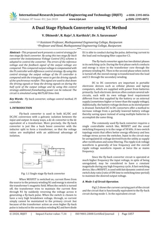
  • 1. International Research Journal of Engineering and Technology (IRJET) e-ISSN: 2395-0056 Volume: 07 Issue: 01 | Jan 2020 www.irjet.net p-ISSN: 2395-0072 © 2020, IRJET | Impact Factor value: 7.34 | ISO 9001:2008 Certified Journal | Page 1057 A Dual Stage Flyback Converter using VC Method V. Dhinesh1, R. Raja2, S. Karthick3, Dr. S. Saravanan4 1,2,3Assistant Professor, Muthayammal Engineering College, Rasipuram 4Professor and Head, Muthayammal Engineering College, Rasipuram ---------------------------------------------------------------------***---------------------------------------------------------------------- Abstract - This proposed work presents a control strategy for two stage fly-back converter. By using this two stage fly-back converter the instantaneous Voltage Control (VC) scheme is adopted to control the converter. The errors of the reference voltage and the feedback signal of the output voltage are compared. This compared output voltageiscompensatedwith the PI controller with difference control strategy. By usingthis control strategy the output voltage of the PI controller is compared with the triangular wave to get the driving signals of the synchronous rectifier. This signal are used to shut down the driving signals or keep the driving signals on during the half cycle of the output voltage and by using this control strategy additional freewheeling power can be reduced. The circuit is simulated using MATLAB Simu-link. Key Words: Fly back converter, voltage control method, PI controller. 1. INTRODUCTION Fly-back converter is used in both AC/DC and DC/DC conversion with a galvanic isolation between the input and output. In many ways, a dc-dc converter is the dc equivalent of a transformer. More precisely, the fly-back converter is just like a buck boost converter with the inductor split to form a transformer, so that the voltage ratios are multiplied with an additional advantage of isolation. Fig: 1.1 Single stage fly-back converter When MOSFET is switched on, current flows from the source to the primary winding N1 andenergyisstoredin the transformer’s magnetic field. When the switch is turned off, the transformer tries to maintain the current flow through N1 by suddenly reversing the voltage across it generating a fly-back pulse. When the switch is chosen to have a very high breakdown voltage, through, so current simply cannot be maintained to the primary circuit .but because of the transformer action an even higher fly-back pulse is induced in the secondary windingN2andherediode D1 is able to conduct during the pulse, delivering current to the load and recharging filter capacitor C1. The fly-back converteragain hastwodistinctphases in its switching cycle. During the first phase switch conducts and energy is store in the transformer core through the primary winding N1. Then in the second phase when switch is turned off, the stored energy is transformed into the load and C1 through the secondary winding. DC to DC converters are important in portable electronic devices such as cellular phones and laptop computers, which are supplied with power from batteries primarily. Such electronic devices often contain several sub- circuits, each with its own voltage level requirement different from that supplied by the battery or an external supply (sometimes higher or lower than thesupplyvoltage). Additionally, the battery voltage declinesasitsstoredpower is drained. Switched DC to DC converters offer a method to increase voltage from a partially lowered battery voltage thereby saving space instead of using multiple batteries to accomplish the same thing. The commonly used fly-back converter requires a single controllable switch like, MOSFET and the usual switching frequency is in the range of 50 kHz. A two-switch topology exists that offers better energy efficiency and less voltage stress across the switches. Input to the circuit may be unregulated dc voltage derived from the utility ac supply after rectification and some filtering. The rippleindcvoltage waveform is generally of low frequency and the overall ripple voltage waveform repeats at twice the ac mains frequency. Since the fly-back converter circuit is operated at much higher frequency the input voltage, in spite of being unregulated, may be considered to have a constant magnitude during any high frequency cycle. A fast switching device, like a MOSFET, is used withfastdynamiccontrol over switch duty ratio (ratio of ON time to switchingtime-period) to maintain the desired output voltage. A. Mode-1 of Circuit Operation. Fig1.2 shows the current carrying part of the circuit and the circuit that is functionally equivalent to the fly-back circuit during mode-1. In the equivalent circuit
  • 2. International Research Journal of Engineering and Technology (IRJET) e-ISSN: 2395-0056 Volume: 07 Issue: 01 | Jan 2020 www.irjet.net p-ISSN: 2395-0072 © 2020, IRJET | Impact Factor value: 7.34 | ISO 9001:2008 Certified Journal | Page 1058 Fig 1.2 Current flow path during Mode 1 and equivalent circuit Under Mode-1, the input supply voltage appears across the primary winding inductance and the primary current rises linearly is shown, the conducting switch or diode is taken as a shorted switch and the device that is not conducting is taken as an openswitch.Thisrepresentationof switch is in line with our assumptionwheretheswitches and diodes are assumed to have ideal nature,havingzerovoltage drops during conduction and zero leakagecurrentduring off state. B. Mode-2 of Circuit Operation Mode2 starts when switch ‘S’ is turned off after conducting for some time.Theprimarywindingcurrentpath is broken and according to laws of magnetic induction, the voltage polarities across the windings reverse. Reversal of voltage polarities makes the diode in the secondary circuit forward biased. Fig 1.3 Current flow path during Mode 2 an equivalent circuit C. Mode-3 of Circuit Operation Mode2 ends with turn ON of switch ‘S’ and then the circuit again goes to Mode-1 and the sequence repeats. The equivalent circuit during mode-3 of circuit operation.Itmay be noted here that even though the two windings of the fly- back transformer don’t conduct simultaneouslytheyarestill coupled magnetically (linking the same flux) and hence the induced voltages across the windings are proportional to their number of turns. Fig 1.4 Current flow path during Mode3 and equivalent circuit 2. Two stage fly-back converter using synchronous rectifier Most DC to DC converters are designed to move power in only one direction, from the input to the output. A bi-directional converter can move power in either direction, which is useful in applications requiring regenerative braking. One of the important features of DC-DC converters is the use of synchronous rectification which replaces the flywheel diode with a power MOSFET with low "On" resistance, thereby reducing switching losses. Fig 2.1 Block diagram of Fly-back converter The DC supply is given to the fly-back inverter, the primary winding of the fly-back transformer is directly connected to the input dc voltage. Fly back Inverter is used to convert dc to ac voltage. By using thisfly-back inverter the phase shift pulse method is used to control the inverter. It is directly connected to the fly-back transformer. High frequency transformer is used for step down purpose. The transformer size should be small due to high frequency. It is also used for isolation purpose. Fly-back transformer works differently from a normal transformer. In a normal transformer, under load, primary and secondary windings conduct simultaneously such that the ampere turns of primary winding is nearly balanced by the opposing ampere-turns of the secondary winding (thesmall difference in ampere-turns is requiredto establishfluxinthe non-ideal core).but in fly-back transformer energy is stored in the transformer. Synchronous rectifier is used as a voltage-controlled resistor in a control loop which adjusts the Synchronous rectifier’s resistance so that the output voltage is maintained within the regulation range. Fig 2.2 V-I characteristics of the synchronous rectifier
  • 3. International Research Journal of Engineering and Technology (IRJET) e-ISSN: 2395-0056 Volume: 07 Issue: 01 | Jan 2020 www.irjet.net p-ISSN: 2395-0072 © 2020, IRJET | Impact Factor value: 7.34 | ISO 9001:2008 Certified Journal | Page 1059 With properly designed gate drives. During the time switch Q1 is turned on, energy is stored in the transformer magnetizing inductance and transferred to the output after Q3 is turned off. The figure2.3 shows the two fly-back converters with synchronous rectifier which is operated alternately. This fly-back converter consists of four operation modes. Fig 2.3 circuit diagram of two stage fly-back converter Mode A: When uo > 0 and i o > 0 The two fly-back converters are workinginmodeA. Switch V1 is in the high frequency- modulation mode; V3 is working as a diode (the anti parallel diode)ora synchronous rectifier (SR). While switch V2 is off and V4ison,converterII does not work. The output voltages of converters I and II are uo1 and 0, respectively. The inverter’soutputvoltage,i.e., uo, is equal to uo1. Fig 2.4 Mode A circuit diagram of two stage fly-back converter Mode B: When uo < 0 and i o > 0 The two fly-back converters operation are in mode B. Switch V4 is working in the high frequency- modulation mode; V2 is working as a diode. While switch V1 is off and V3 is on, converter I do not work. Fig 2.5 Mode B circuit diagram of two stage fly-back converter Mode C: When uo < 0 and io < 0 The two fly-back converters operation are in mode C. Switch V2 is in the high-frequency modulation mode; V4 works as a diode. On the other hand, converterIdo notwork. The output voltages of converters I and II are 0 and uo2, respectively. The output voltage of the inverter is uo = −uo2. The freewheeling power is also 0.It shows the equivalent circuit. Fig 2.6 Mode C operation of two stage fly-back converter Mode D: When uo > 0 and i o < 0: The inverter is working in mode D. Switch V1 is in the high-frequency modulation mode; V3 is working as a diode. On the other hand, converter II does not work. The output voltages of converters I and II are uo1 and 0, respectively. Fig 2.7 Mode D operation of two Stage fly-back converters The fly-back transformer is used for voltage isolationaswell as for better matching between inputandoutputvoltage and current requirements. Primary and secondary windings of the transformer are wound to have good coupling. 3. PI CONTROLLER A PI Controller (proportional-integral controller)is a feedback controller which drives the plant to be controlled with a weighted sum of the error (difference between the output and desired set-point) and the integral of that value. PI controllers are used for the closed loop system. The output voltage is compared with the triangular wave by using conditional operator. The output pulses of this pi controller are given to synchronous rectifier. This output pulses are used for synchronous rectifier to generate the pulses with 180 phase shift.
  • 4. International Research Journal of Engineering and Technology (IRJET) e-ISSN: 2395-0056 Volume: 07 Issue: 01 | Jan 2020 www.irjet.net p-ISSN: 2395-0072 © 2020, IRJET | Impact Factor value: 7.34 | ISO 9001:2008 Certified Journal | Page 1060 Fig 3.1 Simulink model of PI Controller A. Simulation results of two stage fly-back converter The input dc supply is given tothefly-backinverterwhich converts dc to ac voltage by using the fly-back transformer. The primary of the fly-back transformerisdirectlyconnected to the input dc voltage. The main advantage of this fly-back transformer is it stores the energy when compared to the normal transformer. Fig 4.1 Open loop circuit diagram of two stage fly-back converter When the switch is chosen to have a very high breakdown voltage, through, so current simply cannot be maintained to the primary circuit .but because of the transformeraction an even higher fly-back pulse is induced in the secondary winding N2 and here diode D1 is able to conduct during the pulse, delivering current to the load and recharging filter capacitor C1.The fly-back converter again has two distinct phases in its switching cycle. The waveform shows the input voltage of the dc-dc converter with two stage fly-back converter is 24v.The primary winding of the fly-back transformer is directly connected to the dc input voltage. Fig 4.2 Input voltage B. Triggering pulses The waveforms which are shown below are the triggering pulses of the MOSFET’sSa andSb.Thepulsewidth which are given for the triggering pulse p1 is 25% and the phase delay is zero and the pulse width which are given for the triggering pulse p2 is 25% and the phase delay is 0.01e- 3.So for the two MOSFETs Sa and Sb the phase shift is 180.the amplitude of these triggering pulse is 1 which is shown in the waveforms that is voltage verses time period. Fig 4.3 Triggering pulses of the fly-back inverter C. Output voltage of fly-back converter 1 The waveform shows the output voltage of the fly- back converter1 where the input voltage is 24v it has been boosted to 35v.so it is a boost converter. The waveform shows the voltage verses time. Fig 4.4Output voltage of converter 1
  • 5. International Research Journal of Engineering and Technology (IRJET) e-ISSN: 2395-0056 Volume: 07 Issue: 01 | Jan 2020 www.irjet.net p-ISSN: 2395-0072 © 2020, IRJET | Impact Factor value: 7.34 | ISO 9001:2008 Certified Journal | Page 1061 D. Output voltage of fly-back converter 2 The waveforms shows the output voltage of the fly- back converter2 where the input voltage is 24v it has been boosted to 35v.soit is a boost converter. The waveform shows the voltage verses time. Fig 4.5 Output voltage of converter 2 F. Closed loop circuit of the two stage fly-back converter The circuit diagram showstheclosedloopcontrol of the two stage fly-back converter. Here in this closed loop controller 5v disturbance is given in the input voltage. Total 29v is given in the input voltage with disturbance. By giving the set voltage 35v. The output voltage is maintained as 35v.The errors of the reference voltage and the feedback signal of the output voltage are compensated with a PI compensator. The Output signal of the PI compensator compares with a triangular wave to get the pulse signals of the two switches. The pulses are given to these switches with 180 phase shift. Fig 4.7 closed loop circuit of two stage fly-back converter G. Input voltage with disturbance The waveform shows the input voltage with disturbance. The input voltage of these flyback convertersis 24v where the disturbance given in the input is 5v, so the voltage is increased to 29v, means that the steady state error is introduced from 24v to 29v.disturbance means change in the supply voltage. Fig 4.8 Input voltage with disturbance H. Output voltage with disturbance The waveform shows the closedloopoutputvoltage of the two fly-back converters. Where the set voltage is 35v and the output voltage of these flyback converters is 35 when the disturbance is given as 5v. Fig 4.9 Output voltage of closed loop controller 4. CONCLUSION The two stage fly-back converter for the instantaneous voltage control scheme is adopted to control the dc output voltage. The errors of the reference voltage and the feedback signal of the output voltage are compensated with the PI controller. The output signal of the PI controller compares with a triangle wave to get the driving signals of the two switches. The output signal of the comparator is a square wave that has the same frequency and phase angle with the reference voltage. Thesetriangular carrier waves are used to generate the driving signals on during the half cycle of the output voltage. REFERENCES: [1] Dhinesh.V, “Online Grid Integrated Photovoltaic System with New Level Inverter System” in (IRJET) International Research Journal of EngineeringandTechnology, Volume 5, Issue 12, December 2018, Page. No. 1544-1547.
  • 6. International Research Journal of Engineering and Technology (IRJET) e-ISSN: 2395-0056 Volume: 07 Issue: 01 | Jan 2020 www.irjet.net p-ISSN: 2395-0072 © 2020, IRJET | Impact Factor value: 7.34 | ISO 9001:2008 Certified Journal | Page 1062 [2] Raja.R, Nagarajan.C “Performance Analysis Of LCL-T Filter Based 2 Stage Single Phase Gird Connected Module With ANN Controller Using PV Panel” in (CSTT) Current Signal Transduction Therapy Volume 13, Issue 2, September 2018, Page. No. 159-167. ISSN (Print): 1574- 3624, DOI: 10.217 4/1574362413666180223124608, http://www.eurekaselect .com/160064 /article. [3] Dhinesh.V, “Design of a Boost-Buck Converter Fed PMDC Motor” in (ESTIJ) Engineering Science and Technology- An International Journal Volume 3, Issue 4, August 2013, Page. No. 719-725. [4] Raja.R, Nagarajan.C “Designing of LCL Filter and Stability Analysis of a Three Phase Grid Connected Inverter System” in (IJSETR), International Journal of Science, Engineering and Technology Research Volume 5, Issue1, January 2016, Page.No.306-312. ISSN: 2278 – 7798, http://ijsetr.org/wp-content/uploads/2016/01/IJSETR- VOL-5-I SSUE-1-306-312.pdf. [5] Dhinesh.V, “Design of Non Isolated Voltage Doubler Fed with Sepic Converter” in (IJAIR) International Journal of advanced and innovative research Volume 3, Issue 11, November 2014, Page. No. 124-129. [6] S.Karthick “Step up DC-DC Converter with high voltage gain using switched inductor techniques”, International Journal Of Innovative Research in technology Volume 2, Issue 9, ISSN: 2349-6002,Feb 2016. [7] Raja.R, Nagarajan.C “Analysis of Grid Inverter System Using LCL Filter Based on Active and Passive Damping Methods” in (IJIRSET),International Journal ofInnovative Research in Science,EngineeringandTechnologyVolume 4, Special Issue 6th May 2015, Page.No.1244-1253. ISSN (Print): 2347 – 6710, http://www.ijirset.com/upload/2015/m ulticon/eee/33_RC.pdf. [8] Dhinesh.V, “Soft Switching with Cascaded Transformers to Drive the PMDC Motor” in (IJAREEIE) International Journal of Advanced Research in Electrical, Electronics and Instrumentation Engineering Volume 4, Issue 2, February 2015, Page. No. 787-794. [9] Raja.R. “An Efficient High-Step-Up Interleaved with a Common Active Clamp DC–DC Converter for Electric Vehicle” in (IEEE), Institute of Electrical and Electronics Engineers Explore on 10th to 12th April 2013, Page.No.760-764.DOI: 10.1109/ICEETS.2013.6533480, https://ieeexp lore.ieee.org/document/6533480. [10] S.Karthick “High Step-Up DC-DC Converter Based on Voltage Multiplier Cell and Voltage-Stacking Techniques for Renewable Energy Applications”, International Research Journal of Engineering and TechnologyVolume 5, Issue 11, e-ISSN: 2395-0056,Nov 2018 [11] Raja.R. “Performance of Variable Frequency ISPWM Technique for a Cascade Multilevel Inverter” in (IEEE), Institute of Electrical and Electronics Engineers Explore on 10th to 12th April 2013, Page.No.611-616. DOI: 10.1109/ ICEETS.2013.6533455, https://ieeexplore.ieee.org/docum ent/ 6533455. BIOGRAPHIES Mr. V. DHINESH was born in 1988 at Salem, Tamilnadu India. He is a research scholar in Anna University, Chennai. He received the M.E degree in Power Electronics & Drives at Muthayammal Engineering College Namakkal in 2012 and B.E. degree in at Mahendra Engineering College, Tiruchengodu in 2009. He had worked as a Lecturer in Murugesan Institute of Technology, Salem. Since 2012, he has been working as an Assistant Professor in Muthayammal Engineering College, Tamilnadu, India. Mr. R. RAJA has received his B.E degree in Electrical and Electronics Engineering at Mahendra College of Engineering on 2011 and his M.E degree in Power Electronics and Drives from Sona College of Technology, Salem affiliated under Anna University on 2013. He is currently pursuing his Ph.D. in Electrical Engineering and working as AssistantProfessor in Muthayammal Engineering College., Rasipuram, Tamilnadu, India Mr. S. KARTHICK has received his B.E degree in Electrical and Electronics Engineering at Kavery Engineering College on 2010 and his M.E degree in Power Electronics and Drives from Kavery Engineering College, Salem affiliated under Anna Universityon2015. He is currently working as Assistant Professor in Muthayammal Engineering College., Rasipuram, Tamilnadu, India Dr. S. SARAVANAN received his B.E. Degree in Electrical and Electronics Engineering from Madras University Tamilnadu, India in 2003 and M.E. Degree in Applied Electronics from Anna University, Tamilnadu India in 2005. He received his Ph.D degree in Information and Communication Engineering from Anna University, Chennai. Tamilnadu, India in 2011 and working as Professor& Head in EEE Department, Muthayammal Engineering College, Tamilnadu, India.