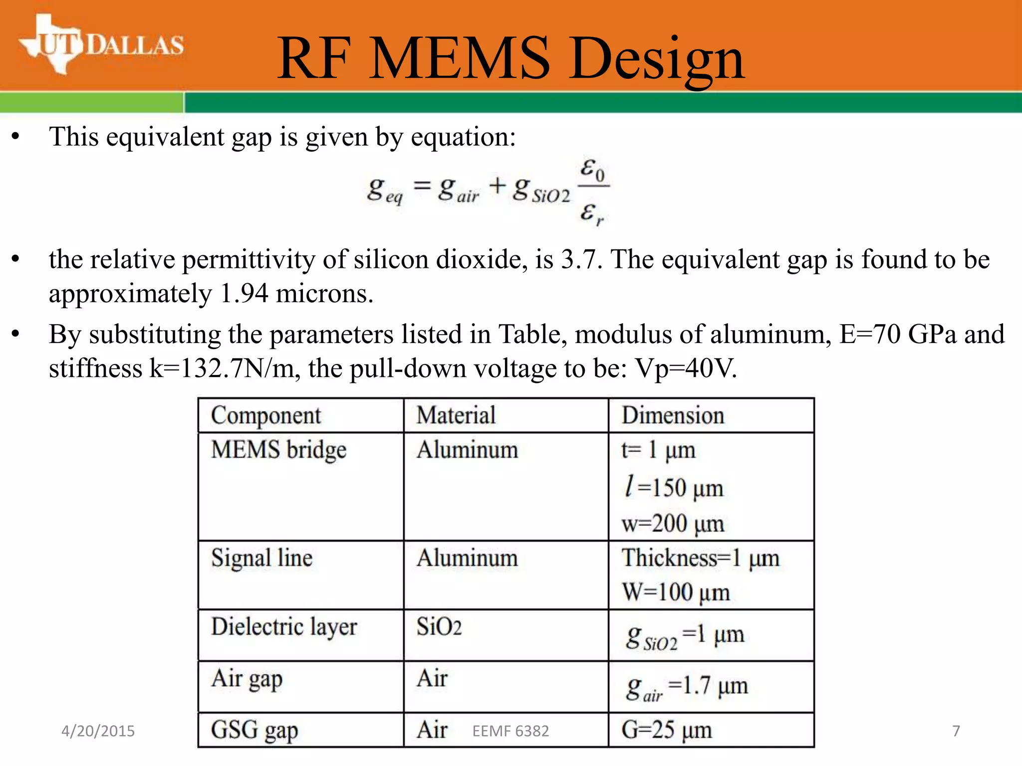
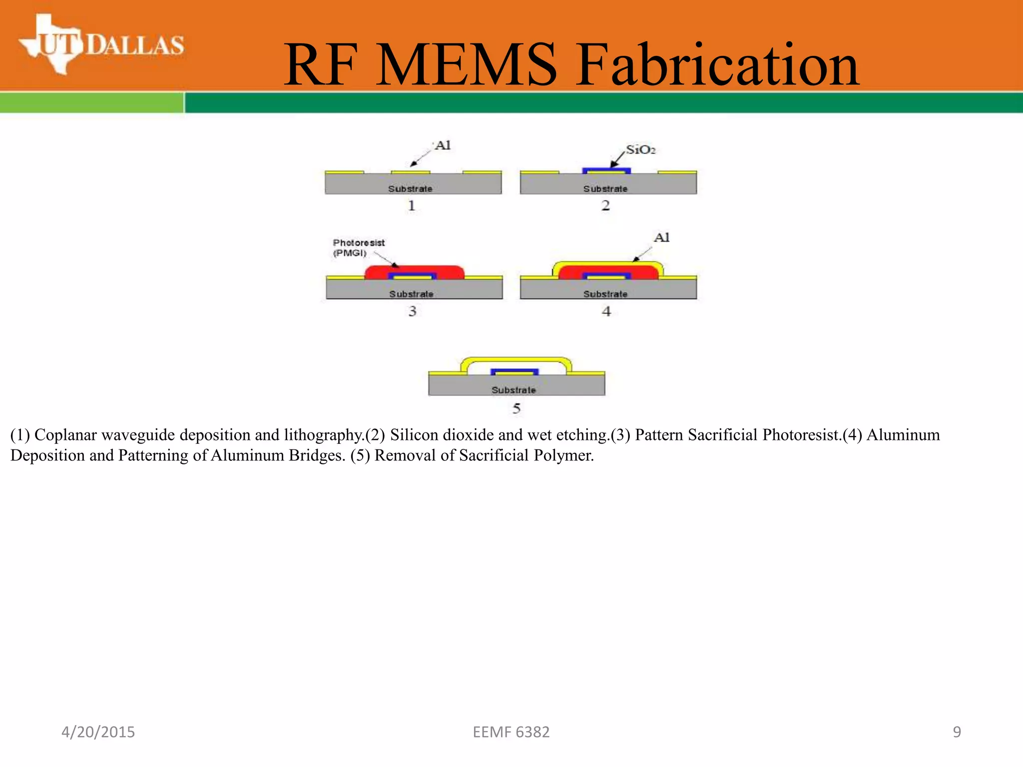
This presentation presents a review of novel technology which provides a promising solution for designing self-powered microsystems. Micro-Electro Mechanical System (MEMS) energy harvesting is an emerging alternative for scavenging energy from natural sources. It has extensive potential in wireless sensor applications to provide a natural energy source that is essentially inexhaustible. It is an increasingly attractive alternative to costly batteries. This essentially free energy source is available maintenance-free throughout the lifetime of the application. Many systems, such as wireless sensor networks, portable electronics and cell phones, can use this technology as a power source. Although some types of MEMS, such as electro-magnetic MEMS, electrostatic MEMS, and piezoelectric MEMS, are used to provide energy in various applications, they have several technical barriers that limit their applications, including low efficiency, issues of scaling, and high cost.Novel MEMS solar energy harvesting technology is scalable and also easily integrated in microsystems. The RF MEMS design not only has to provide functional efficiency, but also must work within the limits of maximum charge and discharge conversion efficiency. The energy harvesting technologies currently available which utilizes RF MEMS to convert solar energy into charge, can achieve better benefits than photovoltaic cells. In this presentation the design,fabrication, testing and evaluation of RF MEMS and its working limits in charging and discharging is illustrated.
1. RF MEMS in Energy Harvesting
Prepared By
Aalay D. Kapadia (adk130330)
4/20/2015 EEMF 6382 1
2. Disclaimer
This work was done as part of coursework of course EEMF 6382 under guidance of
Prof. Siavash Pourkamali Anaraki (Ph.D.) at University Of Texas At Dallas. Any
opinions, findings and conclusions, or recommendations expressed in this material are
those of the authors and do not necessarily reflect those of Prof. Siavash Pourkamali
Anaraki (Ph.D.) and University Of Texas At Dallas.
Reference Paper : Energy Harvesting Using RF MEMS By:Yunhan Huang, Ravi
Doraiswami, Michael Osterman, and Michael Pecht;Center for Advanced Life Cycle
Engineering (CALCE), University of Maryland, College Park, MD 20742, United
States
4/20/2015 EEMF 6382 2
3. Introduction
• As early as 1979, microelectromechanical switches have been used to switch low
frequency electrical signals.
• Switch designs have utilized cantilever, rotary and membrane topologies to
achieve good performance at RF and microwave frequencies.
• Low loss, low power consumption and lack of intermodulation distortion, RF
MEMS switches are an attractive alternative to traditional FET or p-i-n diode
switches in applications where microsecond switching speed is sufficient.
• Capacitive membrane switches have shown excellent performance through
40GHz and for lifetimes in excess of 1 billion cycles, which allows us to employ
them as energy harvesting devices.
• Proposed RF MEMS energy harvesting device is fabricated on a single chip, chip
has a small form factor and an excellent integration and performance efficiency.
• Using discontinuous electrostatic charge transfer, allows ions to diffuse and
redistribute more evenly and to scale to different sizes of the MEMS.
• These advantages leverage RF MEMS energy harvesting devices to achieve
greater scalability and higher efficiency than conventional technologies.
4/20/2015 EEMF 6382 3
4. RF MEMS Design
• The capacitive RF MEMS switch here is a co-planar waveguide (CPW) shunt
switch.
• The RF MEMS switch operates as a digitally tunable capacitor with two states.
• When the membrane is in the up position (switch-off), the signal line sees a small
value of parasitic capacitance, while when the membrane is pulled down by actuated
voltage (switch-on), the signal line sees a high value capacitor shunted to ground.
• Operation of a RF MEMS switch & 1-D linear electromechanical model of RF
MEMS switch:
4/20/2015 EEMF 6382 4
5. RF MEMS Design
• The membrane is subjected to a distributed force across the entire membrane.
• The spring constant:
• where E is the Young’s Modulus of the material, and w, t, and l are the width,
thickness, and length of the membrane, respectively.
• When voltage is applied between the membrane and the signal line, an electrostatic
force is induced on the membrane.
• In order to approximate this force, the membrane over the signal line is modeled as a
parallel-plate capacitor.
• Although the actual capacitance is about 20-40% larger due to accumulated fields,
this approximation is quite accurate for long, planar systems like the RF MEMS
structure.
• Given that the width of the signal line is W, the parallel plate capacitance is
• where g is the height of the membrane above the signal line.4/20/2015 EEMF 6382 5
6. RF MEMS Design
• The electrostatic force induced as charge provides a capacitance, given by
• where V is the voltage applied between the membrane and the signal line.
• The electrostatic force is evenly distributed across the section of the membrane
above the signal line.
• Therefore, the appropriate spring constant can be used to determine the distance that
the membrane moves under the applied force.
• The pull-down voltage can be found from:
• where Vp is pull down voltage, k is the spring constant of membrane, and g is the
equivalent gap between membrane and signal line.
• When the RF MEMS is in its initial undisplaced position (switch-off), the gap
consists of two dielectric materials, namely air and SiO2.4/20/2015 EEMF 6382 6
7. RF MEMS Design
• This equivalent gap is given by equation:
• the relative permittivity of silicon dioxide, is 3.7. The equivalent gap is found to be
approximately 1.94 microns.
• By substituting the parameters listed in Table, modulus of aluminum, E=70 GPa and
stiffness k=132.7N/m, the pull-down voltage to be: Vp=40V.
4/20/2015 EEMF 6382 7
8. RF MEMS Fabrication
• The membrane is deposited over a sacrificial polymer layer that is released at the
end of the surface micromachining process.
• After the sacrificial layer is released, the aluminum membrane is left suspended over
the dielectric layer. Its natural state is in the “up” or unactuated position.
• When a sufficient DC electrical potential is applied between the membrane and
electrode, the membrane snapped down into the actuated state.
• The metal membrane is fabricated using aluminum because of its high resistance to
fatigue and low electrical resistance.
• A 1-micron, nanoporous SiO2 dielectric isolation layer which separates the
membrane and signal line is deposited using a Uniaxis PECD machine.
• The top and cross-sectional view of the RF MEMS.
The RF MEMS switch under microscope.4/20/2015 EEMF 6382 8
9. (1) Coplanar waveguide deposition and lithography.(2) Silicon dioxide and wet etching.(3) Pattern Sacrificial Photoresist.(4) Aluminum
Deposition and Patterning of Aluminum Bridges. (5) Removal of Sacrificial Polymer.
RF MEMS Fabrication
4/20/2015 EEMF 6382 9
10. RF MEMS Characterization
• The electromechanical and RF signal properties of the MEMS are characterized after
fabrication.
• A ground-signal- ground (GSG) probe with a 250 micron pitch with appropriate bias tee and a
network analyzer were used to make time domain reflectometry (TDR) analysis of the RF
MEMS to extract S11 insertion loss parameters and paracitics.
• The pull-down voltage required to change the capacitance of
the switch is 35 volts. This value is less than the analytical
calculation, but still on the same order of magnitude.
• The divergence between experimental data and the 1-D model
exists because the model used the assumptions that there is no
fringing electric field and that the membrane is a flat rigid
plate and is subjected to the force across its entire area.
• The resonance frequency of RF MEMS is found to be around
2.5MHz.
The GSG probe was connected to a RF MEMS switch
4/20/2015 EEMF 6382 10
11. Energy Stored by RF MEMS
• The novel design replaces the externally applied bias voltage with the charge
generated by a coating of the photosensitive material.
• The electric charge is generated by photosensitizing dye; the charge generated is
stored between the gaps of the membrane and signal line of a RF MEMS structure.
• By controlling the charging sequence, the electric charge can be stored in the RF
MEMS structures and then discharged as pulsed energy to an external load or
rechargeable batteries.
• Thus the output voltage can be adjusted by controlling the on/off frequency of
operation of the switch.
• Membrane overlap over the signal isolation layer plays an important role in
determining the maximum energy that can be stored per area of the RF MEMS.
• The energy stored is determined by calculating the capacitance of the RF MEMS
structure.
• The capacitance was derived: C=0.3 pF (switch off), C= 1 pF (switch on),
4/20/2015 EEMF 6382 11
12. Energy Stored by RF MEMS
• For each RF MEMS of 150*200 μm, the charge stored by the can be found by
equation Q = C x V , where V is the voltage level generated by the photosensitive
coating.
• Therefore, by using the pull-down voltage and switch-on capacitance, a maximum
charge of 35 pC was found to be stored and discharged per cycle per switch.
(1) Diagram of the concept of novel device (2)The structure and operation of the novel energy harvester. By applying a photosensitive coating and
transparent electrode, the electric charge can be generated and stored in the RF MEMS structure.
4/20/2015 EEMF 6382 12
13. Reliability Concerns
• Mechanical failures such as creep and fatigue are not a big problem because the
vertical displacement of the center point of the membrane (~2 μm) is much smaller
than its length (150 μm).
• RF MEMS is subjected to the charge and discharge of electrons generated by
photosensitive material, the electrostatic discharge-induced failure (ESD) dominates
the RF MEMS’ reliability issues.
• ESD results in charge injection and charge trapping in the interface between the
insulation layer and the metal due to the ultrahigh electric strength.
• If RF MEMS is continuously exposed to an electrostatic discharge pulse, both its
electromechanical properties (capacitance-voltage curve) and its RF properties
(insertion loss, return loss) continue to shift until the point where the charge density
reaches a critical value which eventually leads to the breakdown of the insulation
layer.
4/20/2015 EEMF 6382 13
14. Conclusion
• These devices are in high demand for use in wireless sensor networks, portable
electronics, etc. Unfortunately, there is very little literature available that deals with
models for energy harvesting using RF MEMS.
• In order to achieve optimum charge and discharge, it is necessary to compute the
membrane pull down voltage. The pull down voltage of the RF MEMS was found to
be 35V with a resonant-frequency of 25 MHz .
• For every charge discharge cycle, it was found that 1pF of capacitance corresponds
to the switch on capacitance.
• This procedure results in (2.18x10^8) electrons charged and discharged in each
cycle. The effect of ESD on the performance and lifetime of the device were also
evaluated.
• The choice of the right photosensitive material will result in maximum energy
conversion.
• Future work will focus on optimizing RF MEMS design to store electronic charges
from constant and pulsed energy charge inputs.
4/20/2015 EEMF 6382 14