Downloaded 168 times

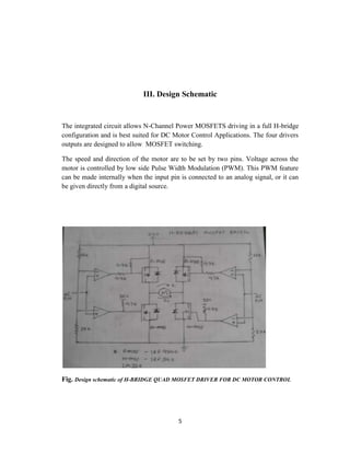
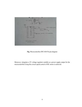

The document discusses an H-bridge quad MOSFET driver for DC motor control, emphasizing its ability to control both the speed and direction of motors using a microcontroller. It details the design schematic, working mechanisms, and components like MOSFETs, comparators, and PWM techniques. Additionally, it highlights the practical applications of H-bridges in robotics and motor control systems.