Downloaded 34 times
![17
17
VACUUM CONTACTOR
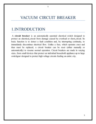
1.INTRODUCTION
A contactor is an electrically controlled switch used for switching a power circuit,
similar to a relay except with higher current ratings.[1] A contactor is controlled by
a circuit which has a much lower power level than the switched circuit. Contactors
come in many forms with varying capacities and features. Unlike a circuit breaker,
a contactor is not intended to interrupt a short circuit current. Contactors range
from those having a breaking current of several amperes to thousands of amperes
and 24 V DC to many kilovolts. The physical size of contactors ranges from a
device small enough to pick up with one hand, to large devices approximately a
meter (yard) on a side.Contactors are used to control electric motors, lighting,
heating, capacitor banks, and other electrical loads
All the contactors are available, on request, in one of the two following
versions.
Single Command Operated(SCO):
closing takes place by supplying auxiliary power to the special input of the
multivoltage feeder. On the other hand, opening takes place when the
auxiliary power is either voluntarily cut off (by means of a command) or
involuntarily (due to lack of auxiliary power in the installation).
Double Command Operated(DCO):
closing takes place by supplying the input of the closing command of the
apparatus in an impulsive way. On the other hand, opening takes place when
the input of the opening command of the contactor is supplied in an
impulsive way.](https://image.slidesharecdn.com/be029e63-69a0-4906-b6ad-796b599f9bce-160412115913/85/ABB-17-320.jpg)

This document is a report on an internship at ABB in Nashik submitted by Amol Nanaji Bagul. It includes an acknowledgements section thanking those who helped with the internship. The document then covers topics related to vacuum circuit breakers and vacuum contactors, including their construction, operating principles, testing procedures, and applications. Sections describe key components like vacuum interrupters, operating mechanisms, and control circuits. Maintenance and servicing are also discussed.


![protection of transmission lines[distance relay protection scheme]](https://cdn.slidesharecdn.com/ss_thumbnails/os-exe3-23-may2011-sr-i-776s21tr-lineprotection-120425095503-phpapp02-thumbnail.jpg?width=640&height=640&fit=bounds)


