Downloaded 685 times

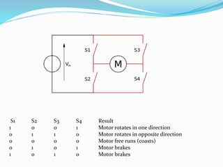
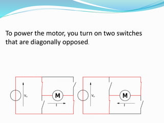
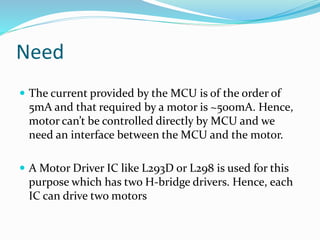
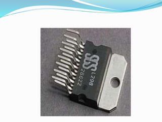
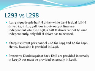
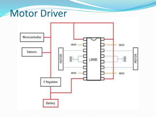
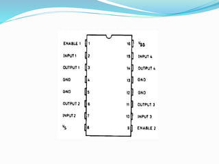

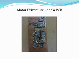

An H-bridge circuit allows voltage to be applied across a motor in either direction, enabling full control over the motor's direction and speed. It is commonly used with a motor driver integrated circuit like the L293D or L298, which contains H-bridge components and can switch higher motor currents than a microcontroller alone. These ICs act as switches to control two DC motors independently according to the logic applied to their inputs.


